
The DC Motor is an electrical machine which converts mechanical energy into electrical energy. The basic principle of working is based on production of induced emf. In the below article we discuss the construction and working of DC motors.
Construction of DC Motor
Construction – The illustration shown below is of a simple generator, the main components are
1) Yoke – The poles get mechanical support from the Yoke. It carries the magnetic flux produced by the pole in the outermost frames. Cast iron and rolled Steel are used to manufacture Yolk.
2) Pole shoes – Pole shoes are made of annealed Steel. They are laminated and are piled up under hydraulic pressure.They extend the flux in the air gap.The cross-sectional area is large hence the reluctance is reduced.
3) Held coils –Copper wires are wounded around the core. When the current passes through the coil, flux is produced.
4) Armature core – Reluctance path to the flux is provided through armature. The conductor coil tends to rotate, which sequentially asserts magnetic flux produced. They are made up of circular sheets and are cylindrical in shape.
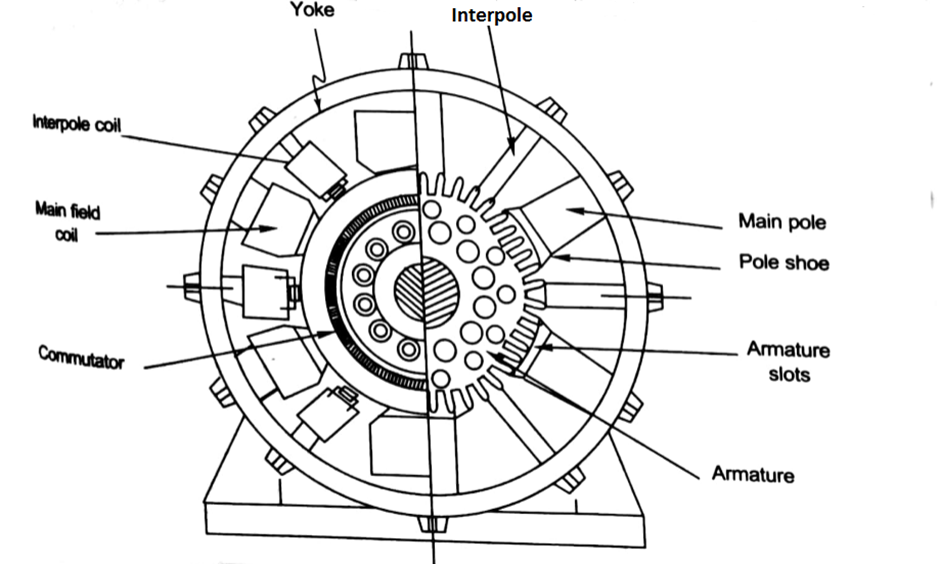
5) Armature Windings – The windings are arranged in armature slots.Tough insulating material are used for lining the slots. The useful EMF is stimulated in the windings.The stimulated EMF is then received across brushes.
6) Commutator – The function of the commutator is to collect current from the armature and then provide it to the load. Direction of current between the rotor and external circuit reverses periodically. It consists of metal segments which are insulated from each other by a thin layer of Mica. The number of metal segments is equal to number of armature coil. It is also cylindrical in shape
7) Brushes and bearings – Carbon or graphite are used to make brushes. Current from the commutator is collected by brushes. They are kept in brush holders and mounted on a spindle. Then amount of current collected from the commutator is dependent upon the number of brushes per spindle.
Derivation of back emf
In a DC motor when the armature rotates the conductors also rotate and hence cut the flux. As per the law of EMI the magnitude of induced EMF is in the opposite direction to the magnitude of applied voltage. As it has opposite direction so it is referred to as back EMF (Eb).
Let φ = Flux /pole
P = Number of poles
Total flux produced by poles = φ x P
Time taken to complete one revolution= 60/N
N= speed of conductor(armature) in rpm
Let e be the emf induced by the armature conductor.
Then by Faraday’s Law

Also, we know Induced emf in one conductor is given as
E= φPN/60
Z = total numbers of conductor
A = number of parallel paths
Then,
Z/A = No. of conductors(series connected)
We know that induced emf in each path is same across the line
Therefore,
Induced emf of DC generator
E = emf of one conductor × number of conductors connected in series.
Induced emf of DC generator is then

For Simple wave wound generator numbers of parallel paths are only 2. So, A=2
Therefore,

Simple lap-wound generator
Here, number of parallel paths is equal to number of conductors in one path
i.e. P = A
Therefore,
Induced emf for lap-wound generator is

Then the back emf induced is motor is same as the emf induced in generator
