UNIT 1
WAVE OPTICS
The principle of superposition says:
When two or more waves cross at a point, the displacement at that point is equal to the sum of the displacements of the individual waves.
The individual wave displacements may be positive or negative. If the displacements are vectors, then the sum is calculated by vector addition.
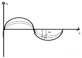
Figure 1
Superposition is an important idea that can explain phenomena including interference, diffraction and standing waves. It works for any type of wave (sound waves, water surface waves, electromagnetic waves...) but only works under certain conditions, which we describe below.
When the waves pass beyond a point of intersection, they separate out again and are unaffected.
The principle of superposition can be applied to any type of wave providing that:
- The waves being superposed are of the same type (e.g. All are electromagnetic waves)
- The medium that the waves are propagating through behaves linearly, i.e. when part of the medium has twice the displacement then it has twice the restoring force. This is usually true when the amplitudes are relatively small. For example, for waves on water, it is a good approximation for small ripples on a pond whose amplitude is much smaller than their wavelength.
If the waves are also coherent - i.e. if they all have the same frequency and a constant phase difference - then the superposition resembles another wave with the same frequency.
Considering two waves, travelling simultaneously along the same stretched string in opposite directions as shown in the figure above. We can see images of waveforms in the string at each instant of time. It is observed that the net displacement of any element of the string at a given time is the algebraic sum of the displacements due to each wave.
Let us say two waves are travelling alone and the displacements of any element of these two waves can be represented by y1(x, t) and y2(x, t). When these two waves overlap, the resultant displacement can be given as y(x,t).
Mathematically, y (x, t) = y1(x, t) + y2(x, t)
As per the principle of superposition, we can add the overlapped waves algebraically to produce a resultant wave. Let us say the wave functions of the moving waves are
y1 = f1(x–vt),
y2 = f2(x–vt)
……….
yn = fn (x–vt)
Then the wave function describing the disturbance in the medium can be described as
y = f1(x – vt)+ f2(x – vt)+ …+ fn(x – vt)
Or, y= 
Let us consider a wave travelling along a stretched string given by,
y1(x,t) = A sin (kx – ωt)
And another wave, shifted from the first by a phase φ, given as
y2(x, t) = A sin (kx – ωt + ϕ)
From the equations we can see that both the waves have the same angular frequency, same angular wave number k, hence the same wavelength and the same amplitude A.
Now, applying the superposition principle, the resultant wave is the algebraic sum of the two constituent waves and has displacement
y(x, t) = A sin (kx – ωt) + A sin (kx – ωt + ϕ)
As, sin A + sin B = 2sin (A+B)/2 .cos (A−B)/2
The above equation can be written as,
y(x, t) = [2A cos ϕ /2 ] sin (kx − ωt + ϕ /2)
The resultant wave is a sinusoidal wave, travelling in the positive X direction, where the phase angle is half of the phase difference of the individual waves and the amplitude as [2cos ϕ /2] times the amplitudes of the original waves.
Hence, the superposition of waves can lead to the following three effects:
- Whenever two waves having the same frequency travel with the same speed along the same direction in a specific medium, then they superpose and create an effect known as the interference of waves.
- In a situation where two waves having similar frequencies move with the same speed along opposite directions in a specific medium, then they superpose to produce stationary waves.
- Finally, when two waves having slightly varying frequencies travel with the same speed along the same direction in a specific medium, they superpose to produce beats.
INTERFERENCE
Interference in light waves occurs whenever two or more waves overlap at a given point.
TYPES OF INTERFERENCE
Interference of light waves can be either constructive interference or destructive interference.
- Constructive Interference: Constructive interference takes place when the crest of one wave falls on the crest of another wave such that the amplitude is maximum. These waves will have the same displacement and are in the same phase.
- Destructive Interference: In destructive interference the crest of one wave falls on the trough of another wave such that the amplitude is minimum. The displacement and phase of these waves are not the same.
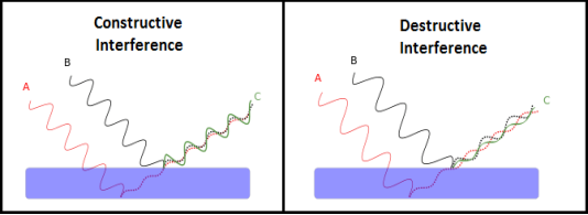
Figure 2
We know that the superposition of two mechanical waves can be constructive or destructive. In constructive interference, the amplitude of the resultant wave at a given position or time is greater than that of either individual wave, whereas in destructive interference, the resultant amplitude is less than that of either individual wave.
Light waves also interfere with each other. Fundamentally, all interference associated with light waves arises when the electromagnetic fields that constitute the individual waves combine.
If two light bulbs are placed side by side, no interference effects are observed because the light waves from one bulb are emitted independently of those from the other bulb. The emissions from the two light bulbs do not maintain a constant phase relationship with each other over time. Light waves from an ordinary source such as a light bulb undergo random phase changes in time intervals less than a nanosecond.
Therefore, the conditions for constructive interference, destructive interference, or some intermediate state are maintained only for such short time intervals. Because the eye cannot follow such rapid changes, no interference effects are observed. Such light sources are said to be incoherent.
In a sustained interference pattern, the position of maximum and minimum intensity regions remains constant with time. To obtain the sustained interference, the following conditions are required:
- The sources must be coherent, that is, they must maintain a constant phase with respect to each other.
- The two light sources must emit continuous waves of the same wavelength and having the same time period.
- The distance between the two sources of light must be small. This gives large fringe width so that the fringes are separately visible.
- The sources should be monochromatic, that is, of a single wavelength.
- The two light sources must emit waves in nearly the same direction.
- Light source must be a point source.
- The distance between the two sources and screen must be large. This gives again large fringe width so that the fringes are separately visible.
THIN FILM INTERFERENCE
A film of thickness from 0.5 to 10 μm is a transparent medium of glass, mica, air enclosed between glass, soap film, etc. When the light is made incident on this thin film partial reflection and partial refraction occur from the top surface of the film. The refracted beam travels in the medium and again suffers partial reflection and partial refraction at the bottom surface of the film. In this way several reflected and refracted rays are produces by a single incident ray. As they moves are superimposed on each other and produces interference pattern.
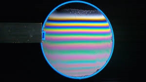
Figure 3
|
INTERFERENCE IN UNIFORM THIN FILM
Consider a thin film of uniform thickness ‘t’ and refractive index μ bounded between air. Let us consider monochromatic ray AB is made incident on the film, at B part of ray is reflected (R1) and a part is refracted along BC. At C The beam BC again suffer partial reflection and partial refraction; the reflected beam CD moves again suffer partial reflection and partial refraction at D. The refracted beam R2 moves in air. These two reflected rays R1 and R2 interfere to produce interference pattern.
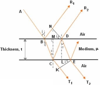
Figure 4
The optical path difference between the two reflected rays

In ΔBDN, sin i = BN / BD and BC = CD as ΔBMC ≡ ΔMCD, therefore

In ΔBMC, cos r = t /BC, therefore


In ΔBMC, tan r = BM / t , therefore

According to snell’s law 


 ................ (1)
Correction on account of phase change at reflection:
When a beam is reflected from a denser medium (ray R1 at B), a path change of λ/2 occur for the ray.
 ….............. (2)
Therefore the true path difference is
Condition of Maxima (Bright Fringe)
Maxima occur when path difference


 ............... (3)
Condition for Minima (Dark Fringe)
Minima occur when path difference


 ................. (4)
INTERFERENCE IN THIN FILM (TRANSMITTED RAYS)
The optical path difference between transmitted rays T1 and T2 will be
This path difference is calculated in the same way as above to get
 ................. (5)
Condition of Maxima (Bright Fringe)
Maxima occur when path difference,

 ................... (6)
Condition for Minima (Dark Fringe)
Minima occur when path difference,

 ............. (7)
PRODUCTION OF COLOURS IN THIN FILMS
When a transparent thin film is illuminated with a white light, coloured fringes are observed. These fringes are due to the interference of light waves reflected from the top and bottom surface of the thin film. The path difference between the reflected waves depends on thickness t of the film, refractive index μ of the film and the angle of refraction r. The reflected light from the thin film of particular thickness t should satisfy the constructive interference condition, i.e.,
2μtcosr=(2n+1)/2
Only this wavelength λ would be present at that point with maximum intensity in the interference pattern in the reflected system. In the interference pattern, each fringe represents the locus of constant film thickness. In such a way, at different portions of the thin film, the reflected light must satisfy the above said condition so that we can observe colours in the interference pattern when thin film is illuminated with white light.
Example: Soap bubble: When white (sun) light is incident on a film of irregular thickness, say soap bubble, at all possible angles, there appears coloured fringes on the film. These fringes are due to interference of light reflected from the two surfaces of the thin film. The interference pattern is produced at a certain place on the soap bubble when its thickness and the angle of incidence of light satisfies the condition of constructive interference for certain wavelength of light. Hence, a soap bubble at that portion would appear with maximum intensity corresponding to that particular wavelength present in the white light. And this happens for each colour in white light. In such away, colours appear on a soap bubble when sunlight is incident on it.
Newton’s Rings are the circular interference pattern first discovered by physicist Sir Isaac Newton in 1704. It is cosists of concentric bright and dark rings with the point of contact of lens and the glass plate as centre,
The fringes obtained by interference of light waves by using the following arrangement
When a Plano convex lens with large radius of curvature is placed on a plane glass plate such that its curved surface faces the glass plate, a wedge air film (of gradually increasing thickness) is formed between the lens and the glass plate. The thickness of the air film is zero at the point of contact and gradually increases away from the point of contact.
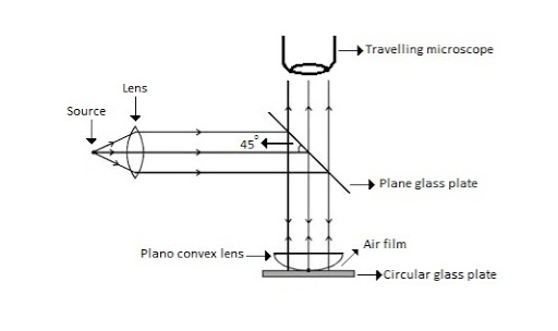
Figure 5: Newton Ring Assembly
If monochromatic (means light with single wavelength) light is allowed to fall normally on the lens from a source 'S', then two reflected rays R1 (reflected from upper surface of the film) and R2 (reflected from lower surface of the air film) interfere to produce circular interference pattern. This interference pattern has concentric alternate bright and dark rings around the point of contact. This pattern is observed through traveling microscope.
MATHEMATICAL ANALYSIS OF NEWTON’S RING
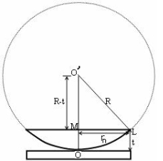
Figure 6
(OL)2 =(O’M)2-(ML)2 ……….(1)
R2=(R-t)2 +rn2
R2=R2 +t2-2Rt +rn2
Radius is large as compared to the thickness
So t2 is neglected as t2<< R2
R2=R2 +-2Rt +rn2
2Rt =rn2
Thickness of the film t =rn2 /2R ……….(2)
THEORY OF FRINGES:
The effective path difference between the two reflected rays R1 and R2 for a wedge shaped film from equation
∆ = 2μtcos(r+θ) +λ/2 ……….(3)
If the light is incident normally on the lens,
r = 0 and near to point of contact θ is small;
Therefore near point of contact, (r+θ) approaches to 0 and cos(r+θ)=cos0=1
Therefore
∆ = 2μt+λ/2 ……….(4)
Also At point of contact t = 0 therefore the effective path difference ∆ = λ/2
Which is odd multiple of λ/2 Therefore the Central fringe is dark.
BRIGHT FRINGE : CONDITION OF MAXIMA
For the condition of maxima the effective path difference
∆ = ±nλ
Using equation (4) ∆ = 2μt+λ/2 we have
2μt+λ/2= ±nλ
2μt = ± (2n-1)λ /2 ……….(5)
DIAMETER OF BRIGHT RINGS
We know by equation (2) t =rn2 /2R substitute in equation (5) we have
2μ (rn2 /2R) = ± (2n-1)λ /2
rn2 = ± (2n-1)λR /2μ
We know diameter D=2r and for nth fringe Dn=2rn
So we have Dn2=± 2(2n-1)λR /μ
Dn=
The medium enclosed between the lens and glass plate is if air therefore,  =1. The diameter of nth order bright fringe will be
D= n=0,1,2,3,4……. ……….(6)
The diameter of bright ring is proportional to square root of odd natural numbers
DARK FRINGE : CONDITION FOR MINIMA
For the condition of minima, The effective path difference
∆ =± (2n+1)λ /2
2μt+λ/2 =± (2n+1)λ /2
2μt= ±nλ ……….(7)
It is clear that for particular dark or bright fringe t should be constant.
Every fringe is the locus of points having equal thickness. Hence the fringes are circular in shape.
DIAMETER OF DARK RINGS
We know by equation (2) t =rn2 /2R substitute in equation (7) we have
2μ (rn2 /2R ) = nλ
rn2 = nλR/ μ
We know diameter D=2r and for nth fringe Dn=2rn
So we have Dn2= 4nλR/ μ
Dn= 
The medium enclosed between the lens and glass plate is if air therefore,  =1. The diameter of nth order bright fringe will be
Dn=  n=0,1,2,3,4……. ……….(8)
The diameter of dark ring is proportional to square root of natural numbers.
SPACING BETWEEN FRINGES
The Newton’s rings are not equally spaced because the diameter of ring does not increase in the same proportion as the order of ring and rings get closer and closer as ‘n’ increases.
For example the diameter of dark ring is given by Dn=  where n=0,1,2,3,4…….
D3 - D2 = -
-  = (
= ( -
- )
) = 0.635
D7 – D6 = -
-  = (
= ( -
- )
) = 0.392
D10– D9 = -
-  = (
= ( -
- )
) = 0.324
From above result we conclude that the fringe width reduces with increase in n.
DETERMINATION OF WAVELENGTH OF LIGHT
The diameter of the nth order ring is calculated by subtracting the left and right side position of the microscope. As we know that the square of diameter of nth dark ring is

Therefore the square of diameter of (n+p)th ring is

Subtracting both the above equation
 ………...(9)
Therefore
 .............(10)
 …….….(13)
NEWTON’S RING WITH WHITE LIGHT
If the monochromatic source is replaced by the white light, dark and bright fringes are not produced. Because the diameter of the rings depends upon wavelength and it is proportional to the square root of wavelength.
If If the monochromatic source is replaced by the white light superposition of rings take place due to different wavelength. Few coloured rings are seen around dark centre later illumination is seen in the field of view. As shown in below figure.
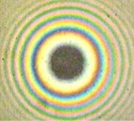
Figure 7
DIFFRACTION
When the light falls on the obstacle whose size is comparable with the wavelength of light then the light bends around the obstacle and enters in the geometrical shadow. This bending of light is called diffraction.
FRAUNHOFFER DIFFRACTION AT SINGLE SLIT
The adjacent figure represents a narrow slit AB of width ‘e’. Let a plane wavefront of monochromatic light of wavelength ' ' is incident on the slit. Let the diffracted light be focused by means of a convex lens on a screen. According to Huygen Fresnel, every point of the wavefront in the plane of the slit is a source of secondary wavelets. The secondary wavelets traveling normally to the slit i.e., along OP0 are brought to focus at -+
AzP0 by the lens. Thus P0 is a bright central image. The secondary wavelets traveling at an angle ' ' are focused at a point P1 on the screen.
The intensity at the point P1 is either minimum or maximum and depends upon the path difference between the secondary waves originating from the corresponding points of the wavefront.
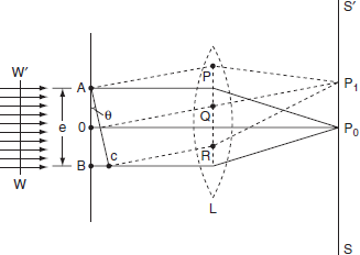
Figure 7
Theory:
In order to find out the intensity at P1, draw a perpendicular AC on BR.
The path difference between secondary wavelets from A and B in direction θ is BC i.e,

So, the phase difference,


Let us consider that the width of the slit is divided into ‘n’ equal parts and the amplitude of the wave from each part is ‘a’.
So, the phase difference between two consecutive points
 ........... (1)
Then the resultant amplitude R is calculated by using the method of vector addition of amplitudes
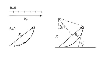
Figure 8
The resultant amplitude of n number of waves having same amplitude 'a' and having common phase difference of ' ' is
' is
 ................... (2)
Substituting the value of  in equation (2)
R = a  ................... (3)
Substituting =
=  .esinθ in equation (3)


As  is small value; sin
R = n
And na = A
Therefore
R =A ................... (4)
Therefore, the Intensity is given by
I =R2 = A2  ................... (5)
Case (i): Principal Maximum:
Eqn (4) takes maximum value for
 = 0
= 0
 =
=  .esinθ = 0
Sinθ = 0 or θ=0
The condition
The condition θ=0 means that this maximum is formed by the secondary wavelets which travel normally to the slit along OP0 and focus at P0. This maximum is known as “Principal maximum”.
Intensity of Principal maxima


Therefore
Imax = R2max = A2
Case (ii): Minimum Intensity positions:
Equation (3) takes minimum values for sin The values of '
 ' which satisfy sin
 are
are


 where
where  ………...(6)
In the above equation (6) n = 0 is not applicable because corresponds to principal maximum. Therefore, the positions according to equation (6) are on either side of the principal maximum.
Case (iii): Secondary maximum:
In addition to principal maximum at  = 0, there are weak secondary maxima between minima positions. The positions of these weak secondary maxima can be obtained with the rule of finding maxima and minima of a given function in calculus. So, differentiating equation (5) and equating to zero, we have
 =
=  (A2
(A2  ) =0
) =0
 = 2A2
= 2A2  (
(  )(
)( =0
=0
A2  0;
0;  =0
=0
Because  =0 correspond to minima positions
 =0
=0
 ………... (7)
The values of ' ' satisfying the equation (7) are obtained graphically by plotting the curves
  and
and  on the same graph.
The points of intersection of the two curves gives the values of  which satisfy equation (7).
The points of intersections are

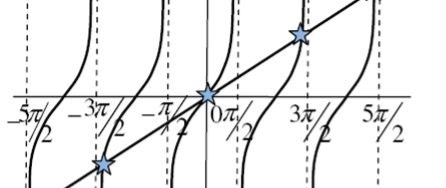
Figure 9
But  , gives principal maximum, substituting the values of
  in equation (5), we get


And so on.
From the above expressions, Imax, I1, I2,I3… it is evident that most of the incident light is concentrated at the principal maximum.
INTENSITY DISTRIBUTION GRAPH
A graph showing the variation of intensity with ' ' is as shown in the adjacent figure
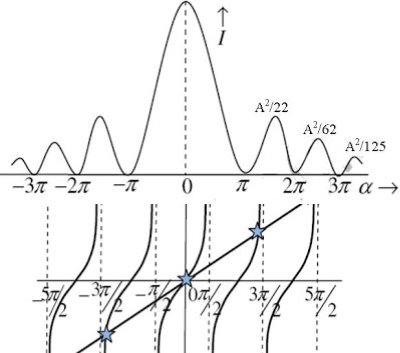
Figure 10
A set of large number of parallel slits of same width and separated by opaque spaces is known as diffraction grating.
Diffraction gratings are much more effective than prisms for dispersing light of different wavelengths so they are used almost exclusively in instruments designed to detect and identify characteristic spectral lines. There is nothing mysterious about these devices.
Fraunhofer used the first grating consisting of a large number of parallel wires placed side by side very closely at regular separation. Now the gratings are constructed by ruling the equidistance parallel lines on a transparent material such as glass with fine diamond point. The ruled lines are opaque to light while the space between the two lines is transparent to light and act as a slit.
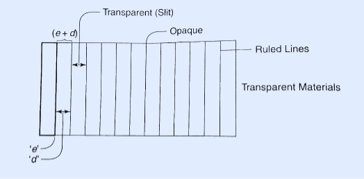
Figure 11
Let ‘e’ be the width of line and ‘d’ be the width of the slit.
Then (e + d) is known as grating element.
If N is the number of lines per inch on the grating then
(𝑒+𝑑)=1𝑖𝑐ℎ=2.54𝑐𝑚
(𝑒+𝑑)=2.54𝑐𝑚/𝑁
Commercial gratings are produced by taking the cost of actual grating on a transparent film like that of cellulose acetate. Solution of cellulose acetate is poured on a ruled surface and allowed to dry to form a thin film, detachable from the surface. This film of grating is kept between the two glass plates.
Example: A parallel beam of monochromatic light of wavelength 500nm is inclined normally on a plane diffraction grating 4000 per centimetre. Calculate the angle of diffraction for first order principal maximum.
Solution:
Given: number of lines per cm =4000
Grating element e+b = 1/4000 cm = 2.5 x 10⁻⁶m
λ=500 nm
Order n =1
(e+b) sinθ =nλ
Sinθ = nλ / (e+b)
Sinθ = 1 x 500 x 10-9 / 2.5 x 10⁻⁶
Sinθ =0.2
θ =sin-1 0.2
θ = 11.5o
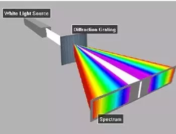
Figure 12
The principle maxima in a grating are formed in direction given by
(e + d)sinθ =nλ
Where (e + d ) is the grating element, ‘n’ the order of the maxima and  the wavelength of the incident light.
1) For a given wavelength  the angle of diffraction
  is different for principal maxima of different orders.
2) For white light and for a particular order n, the light of different wavelengths will be diffracted in different directions.
The longer the wavelength, greater is the angle of diffraction. So in each order, we will get the spectra having as many lines as the wavelength in the light source.
At centre (n = 0, zero order)  gives the maxima of all wavelengths. So here different wavelengths coincide to form the central image of the same colour as that the light source.
Similarly the principal maxima of all wavelengths corresponding to n = 1 will form the first order spectrum, the principal maxima of all wavelengths corresponding to n = 2, will form the second order spectrum and so on.
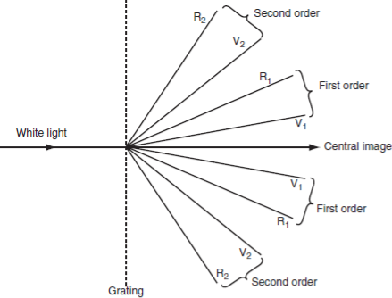
Figure 13
From this we conclude that
Important characteristics of grating spectra:
1) Spectra of different orders are situated symmetrically on both sides of zero order.
2) Spectral lines are almost straight and quite sharp.
3) Spectral colours are in the order from Violet to Red.
4) Spectral lines are more dispersed as we go to higher orders.
5) Most of the incident intensity goes to zero order and rest is distributed among the other orders.
Maximum number of orders formed by a Grating:
The principal maxima in a grating satisfy the condition

Or

The maximum angle of diffraction is 90o, hence the maximum possible order is given by

Consider a grating having grating element which is less than twice the wavelength of the incident light, then


i.e., only the first order is possible.
NUMERICAL PROBLEM
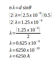
Example: A grating containing 4000 slits per centimetre is illuminated with a monochromatic light and produces the second-order bright line at a 30° angle. What is the wavelength of the light used? (1 Å = 10-10 m)
Solution:
The distance between slits (d) = 1 / (4000 slits / cm) = 0.00025 cm = 2.5 x 10⁻⁴ cm = 2.5 x 10⁻⁶ meters
Order (n) = 2
Sin 30o = 0.5
1 Å = 10-10 m
Wavelength of the light (λ) =?
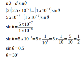
Example: A monochromatic light with a wavelength of 2.5x10⁻⁷ m strikes a grating containing 10,000 slits/cm. Determine the angular positions of the second-order bright line.
Solution:
Given
The distance between slits (d) = 1 / (10,000 slits / cm) = 0.0001 cm = 1 x 10⁻⁴ cm = 1 x 10⁻⁶ m
Order (n) = 2
Wavelength (λ) = 2.5 x 10⁻⁷ m
Angle (θ)
Example: A monochromatic light with wavelength of 500 nm (1 nm = 10-9 m) strikes a grating and produces the second-order bright line at an 30° angle. Determine the number of slits per centimetre.
Solution:
Wavelength (λ) = 500.10-9 m = 5.10-7 m
θ = 30o
n = 2
Distance between slits:
d sin θ = n λ
d (sin 30o) = (2)(5.10-7)
d (0.5) = 10.10-7
d = (10.10-7) / 0.5
d = 20.10-7
d = 2.10-6 m
Number of slits per centimetre:
x = 1 / d
x = 1 / 2.10-6 m
x = 0.5.106 / 1 m
x = 0.5.106 / 102 cm
x = 0.5.104 cm
x = 5.103 /cm
x = 5000 /cm
Example: A monochromatic light with wavelength of 500 nm (1 nano = 10-9) strikes a grating and produces the fourth-order bright line at an 30° angle. Determine the number of slits per centimetre.
Solution:
Wavelength (λ) = 500.10-9 m = 5.10-7 m
θ = 30o
n = 4
Distance between slits:
d sin θ = n λ
d (sin 30o) = (4)(5.10-7)
d (0.5) = 20.10-7
d = (20.10-7) / 0.5
d = 40.10-7
d = 4.10-6 m
Number of slits per centimetre:
x = 1 / 4.10-6 m
x = 0.25.106 / m
x = 0.25.106 / 102 cm
x = 0.25.104 / cm
x = 25.102 per cm
x = 2500 per cm
The phenomena of interference and diffraction confirm the wave nature of light hence neither of these phenomena is able to indentify the nature of waves that light is. These phenomena do not tell whether the oscillation of light waves are longitudinal or transverse in nature. This is accompalished by the study of polarization.
A light wave that is vibrating in more than one plane is referred to as unpolarized light.
Example: Light emitted by the sun, by a lamp in the classroom, or by a candle flame is unpolarized light.
These unpolarized light is created by electric charges that vibrate in a variety of directions, this concept of unpolarized light is difficult to visualize. For simplicity it is helpful to visualize unpolarized light as a wave that has an average of half its vibrations in a horizontal plane and half of its vibrations in a vertical plane. It is possible to transform unpolarized light into polarized light.
Polarized light waves are light waves in which the vibrations occur in a single plane. The process of transforming unpolarized light into polarized light is known as polarization.
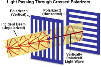
Figure 14
Classification of light
We know that Light is a transverse electromagnetic wave, but natural light is generally unpolarized, all planes of propagation being equally probable.
Linearly Polarized: Light in the form of a plane wave in space is said to be linearly polarized. The electric field of light is limited to a single plane along the direction of propagation.
Circularly Polarized If light is composed of two plane waves of equal amplitude by differing in phase by 90°, then the light is said to be circularly polarized. If the thumb of your right hand were pointing in the direction of propagation of the light, the electric vector would be rotating in the direction of your fingers.
Elliptically Polarized If two plane waves of differing amplitude are related in phase by 90°, or if the relative phase is other than 90° then the light is said to be elliptically polarized. If the thumb of your right hand were pointing in the direction of propagation of the light, the electric vector would be rotating in the direction of your fingers.
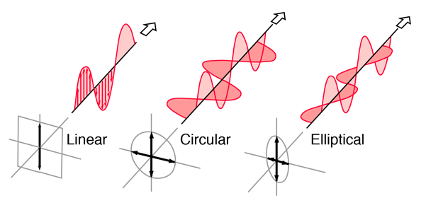
Figure 15: Showimg Linear, Circular and Elliptical Polarization
Production of Polarized Light by Reflection
The Brewster’s law can be used to polarise the light by reflection. When unpolarised light is incident on the boundary between two transparent media, the reflected light is polarised with its electric vector perpendicular to the plane of incidence when the refracted and reflected rays make a right angle with each other.
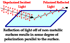
Figure 16
Thus we have seen that when reflected wave is perpendicular to the refracted wave, the reflected wave is a totally polarised wave. The electric field vectors of all unpolarized light may be resolved into two components as follows;
- Tangential component- in the plane of incidence.
- Normal components – in the plane perpendicular to plane of incidence.
The angle of incidence in this case is called Brewster’s angle


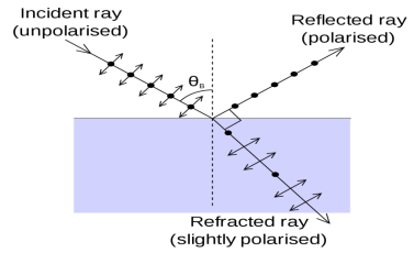

Figure 17
If the angle of incidence θi is varied, the reflected coefficient ‘r’ for the em waves corresponding to the tangential component will vary as shown in figure. As θi increases r will decrease.
At θi = Brewster angle (about 57° for glass) r will be zero and no reflection of the tangential component will take place.
The reflected beam will contain light waves having only the normal component for the electric field as shown in figure that is the reflected light will be plane polorized with the oscillations of electric field vector normal to the plane of incidence.
Cause of Polrizaton by Reflection
The em waves are generated because of the oscillation of electric charge. The electric field vectors of the transmitted ray act on the electrons in the dielectric.
Since the intensity of em wave emitted by the oscillating charge is maximum in a direction normal to the plane of oscillation, and zero along the line of oscillations for the plane polarized light having electric field vector in the plane of incidence, there will be no emition of em waves in a direction normal to the reflected ray. In figre the direction along which no emission should accur is called as zero intensity line. Let the angle between the reflected ray and the zero intensity line be 𝛿 the angle between the reflected and tranmitted ray is π/2 + 𝛿 suppose we arrange the angle of incidence such that
n=sinθi / sinθr
n=sinθi / sin(π/2 – θi)
n=sinθi / cosθi
n=tan θi
That is possible when
θi + θr = π/2 according to Brewster’s law
From figure
θi + θr+ π/2 + = π
As θi + θr = π/2
So π/2+ π/2 + = π
= 0
The line of zero intensity and the refected ray will coincide. Thuse there will be no reflection of light when the angle of incidence is equal to Brewster’s angle.
Thus the unpolarized light can be polarized by reflection as the reflected beam will contain light waves having electric field vector oscilating along normal to the plane of the incidence only.
PRODUCTION OF POLARIZED LIGHT BY REFRACTION
Polarization can also occur by the refraction of light. Refraction occurs when a beam of light passes from one material into another material. At the surface of the two materials, the path of the beam changes its direction. The refracted beam acquires some degree of polarization.
Birefringence, an optical property in which a single ray of unpolarized light entering an anisotropic medium is split into two rays, each traveling in a different direction. One ray (called the extraordinary ray) is bent, or refracted, at an angle as it travels through the medium; the other ray (called the ordinary ray) passes through the medium unchanged.
The ordinary ray and the extraordinary ray are polarized in planes vibrating at right angles to each other. The refractive index of the ordinary ray is constant in all directions; the refractive index of the extraordinary ray varies according to the direction because it has components that are both parallel and perpendicular to the crystal’s optic axis. An extraordinary ray can move either faster or slower than an ordinary ray.
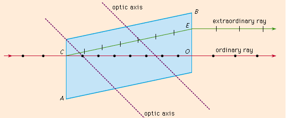
Figure 18
The Figure shows the phenomenon of double refraction through a calcite crystal. An incident ray is seen to split into the ordinary ray CO and the extraordinary ray CE upon entering the crystal face at C. If the incident ray enters the crystal along the direction of its optic axis, however, the light ray will not become divided.
The polarization occurs in a plane perpendicular to the surface. The polarization of refracted light is demonstrated by a unique crystal that serves as a double-refracting crystal.
Iceland Spar (calcite mineral), refracts incident light into two different paths. The light is split into two beams upon entering the crystal.
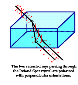
Figure 19
That mean if we see an object through an Iceland spar crystal, two images will observed. These two images are the result of the double refraction of light. Both refracted light beams are polarized - one in a direction parallel to the surface and the other in a direction perpendicular to the surface
Since these two refracted rays are polarized with a perpendicular orientation, a polarizing filter can be used to completely block one of the images. If the polarization axis of the filter is aligned perpendicular to the plane of polarized light, the light is completely blocked by the filter; meanwhile the second image is as bright as can be. And if the filter is then turned 90-degrees in either direction, the second image reappears and the first image disappears.
Negative and Positive Crystals:
Suppose vo and ve be the velocities of the ordinary and extraordinary rays. The crystals in which vo<ve are termed as negative and in which vo>ve are termed as positive. Calcite is negative crystal and quartz is an example of positive crystal.
Uniaxial and Biaxial crystals:
Uniaxial crystal: A crystal which has only one optic axis is called uniaxial crystal. The refractive index of the ordinary ray is constant for any direction in the crystal. Examples:- Calcite, Quartz, Ice, Tourmaline etc.
Biaxial crystal: A crystal which has only two optic axis is called biaxial crystal. The refractive index of the extraordinary ray is variable and depends on the direction. Examples:- Mica, Topaz, Borax etc.
All transparent crystals except those of the cubic system, which are normally optically isotropic, exhibit the phenomenon of double refraction: in addition to calcite, some well-known examples are ice, mica, quartz, sugar, and tourmaline. Other materials may become birefringent under special circumstances.
For example, solutions containing long-chain molecules exhibit double refraction when they flow; this phenomenon is called streaming birefringence. Some isotropic materials like glass may even exhibit birefringence when placed in a magnetic or electric field or when subjected to external stress.
DOUBLE REFRACTION BY NICOL PRISM
This was invented by William Nicol in the year 1828. Nicol prism is made from a double refracting calcite crystal.
A Nicol Prism is a type of polarizer, an optical device used to produce a polarized beam of light.
It is made in such a way that it eliminates one of the rays by total internal reflection, i.e. the ordinary ray is eliminated and only the extraordinary ray is transmitted through the prism.
Construction of Nicol prism:
- Length of calcite crystal is three times its breath.
- The corners A′G′ is blunt and A′C G′E is the principal section with ∠A′CG′ = 71°.
- The end faces A′BCD and EFG′H are grounded so that the angle ACG = 68°.
- The crystal is cut along the plane AKGL. The cut surfaces are polished until they are optically flat and cemented together with Canada balsam.
The refractive index of Canada balsam (1.55) is in between the refractive indices of ordinary (1.658) and extraordinary (1.486) rays in calcite crystal.
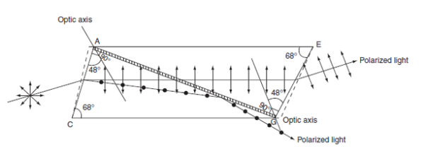 Figure 19: Production of plane polarized light using Nicol prism
Working
- The diagonal AG represents the Canada balsam layer.
- A beam of unpolarized light is incident parallel to the lower edge on the face ABCD.
- The ray gets doubly refracted on entering into the crystal.
- From the refractive index values, we know that the Canada balsam acts as a rarer medium for the ordinary ray and it acts as a denser medium for extraordinary ray.
- When the angle of incidence for ordinary ray on the Canada balsam is greater than the critical angle then total internal reflection takes place, while the exaordinary ray gets transmitted through the prism.
- Nicol prism can be used as an analyser.
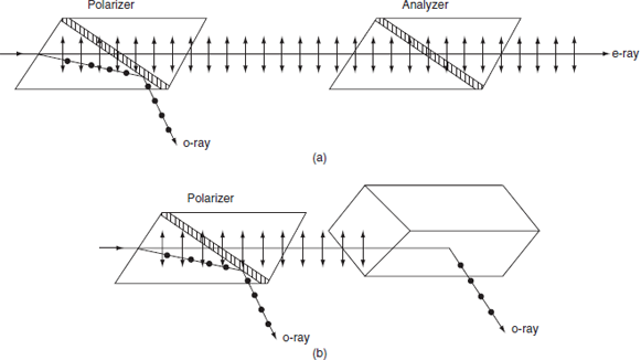
Figure 20: (a) Parallel Nicols; (b) Crossed Nicols
- Two nicol prisms are placed adjacently as shown in figure.
- One prism acts as a polarizer and the other act as an analyzer.
- The exaordinary ray passes through both the prisms.
- If the second prism is slowly rotated, then the intensity of the exaordinary ray decreases.
- When they are crossed, no light come out of the second prism because the e-ray that comes out from first prism will enter into the second prism and act as an ordinary ray. So, this light is reflected in the second prism. The first prism is the polarizer and the second one is the analyser.
POLARIZATION BY HALF WAVE AND QUARTER WAVE PLATE
A wave plate or retarder is an optical device that alters the polarization state of a light beam travelling through it. There are many types of retarders. Some common retarders are quarter-wave (λ/4) plates and half-wave(λ/2) plates.
A half-wave plate functions as a polarization rotator for linearly polarized light. It rotates the polarization of a linearly polarized light by twice the angle between its optic axis and the initial direction of polarization, as shown in Figure 22. It introduces a phase difference of radians between the
A typical wave plate is simply a birefringent crystal or a double refracting plastic foil with a carefully chosen thickness. If a beam of parallel light strikes perpendicularly a wave plate the light beam is splitted into two components due to its double refracting properties. The two components have planes of oscillation perpendicular to each other and slightly different phase velocities.
For a quarter-wave plate the thickness of the foil is chosen in such a manner that the light component whose electric field vector oscillates in parallel to the rotation lever lags by a λ/4 behind other perpendicular oscillating light component. For a half-wave plate the thickness is chosen so that the created phase difference has the amount of λ/2. In this experiment monochromatic light falls on a quarter-wave and half-wave plate. The polarization of the emergent light is investigated at different angles between the optic axis of the wave plates and the direction of the incident light.
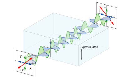
Figure 21
Half wave plate
A half-wave plate functions as a polarization rotator for linearly polarized light. It rotates the polarization of a linearly polarized light by twice the angle between its optic axis and the initial direction of polarization, as shown in Figure 22. It introduces a phase difference of radians between the two components of the electric field vectors.
Suppose a plane-polarized wave is normally incident on a wave plate, and the plane of polarization is at an angle ϕ with respect to the fast axis, as shown. After passing through the plate, the original plane wave has been rotated through an angle 2ϕ.
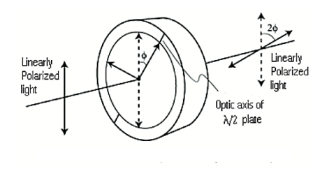
Figure 22
A half-wave plate is very handy in rotating the plane of polarization from a polarized laser to any other desired plane (especially if the laser is too large to rotate). Most large ion lasers are vertically polarized. To obtain horizontal polarization, simply place a half-wave plate in the beam with its fast (or slow) axis 45° to the vertical. The l/2 plates can also change left circularly polarized light into right circularly polarized light or vice versa. The thickness of half waveplate is such that the phase difference is 1/2 wavelength (l/2, Zero order) or certain multiple of 1/2-wavelength [(2n+1)l/2, multiple order].
Quarter Wave Plate
A quarter-wave plate is used to convert linear polarization to circular polarization and vice-versa. In order to obtain circular polarization, the amplitudes of the two E vector components must be equal and their phase difference must be 90 or 270 degrees. A quarter-wave plate is capable of introducing a phase difference of 90 degrees between the two components of incident light. However, this is not enough to produce circular polarization. The direction of polarization of the incident light with respect to the optic axis of the quarter-wave plate is equally important. It is obvious that the amplitudes of the two components will be equal only when the incident linear polarization direction makes an angle of 45 degrees with respect to the optic axis of the crystal(i.e.α= 45degrees). Figure 23 illustrates the conversion of linearly polarized light into circularly polarized light. Note that conversely, if circularly polarized light is incident on a quarter-wave plate, the resulting polarization will be linear, at an angle of 45 degrees with respect to the optic axis. Again, the reason is that a phase difference of 90 degrees is introduced between the two components of the electric field vector, which traces a helix-like path as the circularly polarized wave propagates.
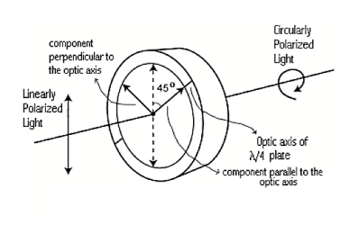
Figure 23
Applications of Interference:
- The phenomenon of light-wave interference with oily or filmy surfaces has the effect of filtering light, and, thus, has a number of applications in areas relating to optics: sunglasses, lenses for binoculars or cameras, and even visors for astronauts.
- Used for Optical Testing: Generally, interference is used in testing surface qualities like: flat surface, spherical surface, roughness of surface etc.
- Used in Space applications -Radio astronomy -Measuring light intensity -In retrieving images from the telescopes.
- The use of interference techniques in microscopy provides a useful tool for scientists and engineers in the investigation and measurement of very small changes in height on a reflecting surface. The interference fringes may be regarded as contour lines spaced at half the wave length of the monochromatic light used for illumination. This gives, in effect, a remarkably high magnification in depth and makes possible the assessment of the variations of flatness and finish of highly finished surfaces and the measurement of the thickness of vacuum evaporated films and the height of surface steps on crystals.
- Another application of the principle of wave superposition is Active Noise Control. It is based on the fact that the pressure waveform generated by a primary source (such as an engine) can be cancelled by the pressure waveform emitted by a secondary source (loudspeakers) driven at the same frequency as the primary source, but with a phase shift of 180 degrees so that the acoustic pressures cancel each other out. This technique has been applied to reduce the annoying noise inside the cabin of propeller aircraft.
Applications of Diffraction
The diffraction grating is an important device that makes use of the diffraction of light to produce spectra. Diffraction is also fundamental in other applications such as x-ray diffraction studies of crystals and holography. Hologram projection is also an example of diffraction and you may have seen one.
- The diffraction grating transforms an incident beam of light into a spectrum. Spectra produced by diffraction gratings are extremely useful in applications from studying the structure of atoms and molecules to investigating the composition of stars. Diffraction is used a lot in discovering the structures of materials and atoms.
- Current research using x-ray diffraction utilizes an instrument called a diffractometer to produce diffraction patterns that can be compared with those of known crystals to determine the structure of new materials.
- It has been used a lot in discovering medicines and drugs.
Applications of Polarization
Polarization is widely used in many applications.
Polaroid glasses are used to reduce the amount of light that is approachable to eye. It is used in sunglasses to reduce the glare.
3D movies are possible because of polarisation of light. It is also used in the entertainment industry to produce and show 3-D movies. Three-dimensional movies are actually two movies being shown at the same time through two projectors. The two movies are filmed from two slightly different camera locations. Each individual movie is then projected from different sides of the audience onto a metal screen. The movies are projected through a polarizing filter. This gives the viewer a perception of depth.
Polarization is used for differentiating between transverse and longitudinal waves.
Laser is an outcome of polarisation of waves.
Infrared spectroscopy uses polarization.
In Chemistry, the chirality of organic compounds is tested using polarization techniques.
Polarization Polaroid filters are used in plastic industries for performing stress analysis tests.
Polarisation is useful in receiving and transmitting wave signals. There has to be an aerial alignment of the polarised waves in the plane in order for them to be able to receive maximum signal.
Our model of the polarization of light provides some substantial support for the wavelike nature of light. It would be extremely difficult to explain polarization phenomenon using a particle view of light. Polarization would only occur with a transverse wave. For this reason, polarization is one more reason why scientists believe that light exhibits wavelike behaviour.