UNIT-II
DIELECTRICS AND MAGNETICS
Definitions:
A dielectric is an electrical insulator that can be polarized by an applied electric field. Or
A dielectric is non-conducting material which stores electrical charges.
In other words, A material that does not conduct electricity but on applying electric field, induced charges produced on its faces. Such an insulator is called Dielectric.
Dielectrics are insulators i.e. non-conducting substances which are bad conductor of electric current. Dielectric materials can stores an electrostatic charge while dissipating minimal energy in the form of heat.
Examples of dielectric are Mica, Plastics, Glass, Porcelain and Various Metal Oxides and even dry air is also example of dielectric. The dielectric constant of a vacuum is, of course, unity.
Classification of Dielectric
The response of a dielectric material depends on the nature of its molecules. The molecules of a dielectric is of two types
- Polar molecules
- Nonpolar molecules
Polar Molecules: Polar Molecules are those in which centre of gravity of positive and negative charge does not coincide with each other. This is because they all are asymmetric in shape. Examples: H2O, CO2, NO2 etc. The molecule of material are composed of two or more different atoms, which have permanently dipole moment because the centre of gravity of positive charge and negative charge does not coincide with each other but seperated by a finite (small) distance.
Normally this type of molecular dipole in polar dielectric are randomly oriented such that their net dipole moment becomes zero and material act as a neutral material.
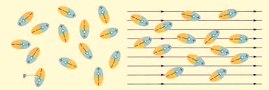
Figure 1
Polar Molecules are those type of dielectric in which the possibilities that the positive and negative molecules will coincide with each other is null or zero.
Non-Polar Molecule: Non-polar molecules are those in which centre of gravity of positive charge and negative charge coincide with each other. The molecule has zero dipole moment as they all are symmetric in shape. Examples: O2, N2, H2 etc.
Dielectrics materials in which the molecule's center of gravity of positive charge and negative charge coincide with each other and so the molecules are electrically neutral and hence zero dipole moment.
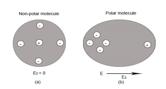
Figure 2
Difference between Dielectric and Insulators
Dielectrics are often confused with insulators. Here are some points of differences
- Dielectric is the material which stores the electrical energy in an electric field whereas insulator is that material which blocks the flow of electrons.
- Dielectric material is polarised whereas insulator material doesn’t get polarised.
- Molecules in dielectric are weakly bounded as compared to molecules in insulator.
- Dielectric material has high dielectric constant whereas insulator has low dielectric constant.
- Examples of Dielectric material are dry air, vacuum, Glass, Porcelain, Various Metal Oxides and distilled water. Whereas Examples of insulator are cotton, plastic, rubber etc.
In dielectric material molecules are tightly bounded to the nucleus and not able to move freely as in case of conductor. But when a dielectric material is placed in an electric field, electric charges do not flow through the material as they flow in case of an electrical conductor but only slightly shift from their average equilibrium positions causing dielectric polarization. Because of dielectric polarization, positive charges are displaced in the direction of the field and negative charges shift in the direction opposite to the field. In dielectric molecules are tightly bound to the nucleus and not able to move freely as in case of conductors. The dielectric material is largely used in the manufacturing of capacitor.
Response of Dielectric to External Electric Field
In case of Polar Molecules -When the electric field is not present, it causes the electric dipole moment of these molecules in a random direction. This is why the average dipole moment is zero. If the external electric field is present, the molecules align themselves in the direction electric field and resulted in having dipole moment.
In case of Non-Polar Molecules – As we know nonpolar molecule has zero dipole moment. In spite of zero dipole, when a dielectric nonpolar material is placed in an electric field. The positive and the negative charges in a nonpolar molecule experience forces in opposite directions. This force causes the separation between the charges and hence nonpolar molecule experiences induced dipole moment.
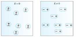
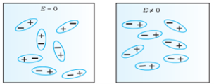
Figure 3(a) (left) Non Polar Molecule Figure 3(b) (right) Polar Molecule
Electronic polarization refers to the separation of centre of positive charge and centre of negative charge in a material.This separation is caused by high electric field.
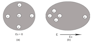
4 Figure (a) shows thecharge distribution of an atom in absence of electric field while figure (b) Show the charge distribution in presence of external electrical field.
Let us consider a single atom of atomic number Z. +e coulomb is the charge of each proton in the nucleus and -e coulomb is the charge of each electron surrounds the nucleus. All electrons in the atom form a spherical cloud of negative charge surrounds the positively charged nucleus. The charge of nucleus is +Ze coulombs and charge of the negative cloud of electrons is -Ze coulombs.
Let us also assume that the negative charge of the electrons cloud is homogeneously distributed on a sphere of radius R. In the absence of external electric field, the center of this sphere and center of nucleus of the atom coincide.
When an external electric field E is applied to the atom. Because of this external electric field the nucleus of the atom is shifted towards negative intensity of the field and the electron cloud is shifted towards the positive intensity of the field.
As due to influence of external electric field the center of nucleus and center of electrons cloud are separated, there will be an attractive force between them according to Coulomb’s law.
Let us suppose x is distance of separation between positive charge nucleus and electron cloud.
Also, Nucleus is considered as point charge. Hence, the electrostatic force acting on the nucleus =+EZe …….(1)
As we know nucleus has been shifted from the center of electrons cloud by a distance x.
By using Gauss’s theorem
The force is only due to electron cloud acting upon nucleus would only be due to the portion of the cloud enclosed by the sphere of radius x. Portion outside the sphere of radius x does not apply any force on the nucleus.
Volume of the sphere of radius x = (4/3)πx3 and
Volume of the sphere of radius R = (4/3)πR3
Now total negative charge of the electron cloud is -Ze …..(2)
Hence, the quantity of negative charge enclosed by the sphere of radius x is,
[-Ze/(4/3)πR3] * (4/3)πx3 = -Ze (x3/ R3) ……..(3)
According to coulomb’s law = q1q2 /4 πR2
Here it becomes charge on electrons q1=-Ze (x3/ R3)
Charge on nucleus q2= Ze
So coulomb’s force = {-Ze (x3/ R3) * Ze}/4πƐox2 = Z2e2x/4πƐo R3 ……(4)
Note- magnitude is taken to account. Neglect negative sign.
i.e. At equilibrium Electrostatic force = Coulomb force .
EZe = Z2e2x/4πƐoR3 ……..(5)
Upon simplify
x = {4πƐoR3/Ze} E
Now dipole moment = either charge * separation between charges i.e. x
= Ze *{4πƐoR3/Ze} E
= 4πƐoR3E
Polarization is number of dipole moment per unit volume. Let us suppose N is the number of dipoles per unit volume so
Pe=4πƐoR3EN
So it is clear that polarization depends upon radius of atom or volume of atom and number of atoms present per unit volume.
Polarization
In previous section we have seen about the dielectric material’s behaviour and we have seen that when the dielectric material is placed in an electric field, then the molecule of polar and non-polar dielectric gains the dipole moment. Then the dielectric is said to be polarised.
Definition:
The diploe moment per unit volume of dielectric material is called the electric polarization of dielectric. It is represented by vector P.
In S.I. System, unit of polarization is C/m2.
When an external electric field is applied to a dielectric material, its behaviour can be determined and is known as Dielectric Polarization that can be understood by the displacement of charges (positive and negative) when an electric field is applied
The main task of the dielectric polarization is to relate macroscopic properties to microscopic properties. Where macroscopic property can be dielectric constant to polarizability.
Polarization occurs through the action of an electric field or other external factors, such as mechanical stress in the case of piezoelectric crystals (piezoelectric crystals are those solid materials which accumulates electric charge within them). Dielectric Polarization can also arise spontaneously in pyroelectric crystals, particularly in ferroelectrics (Ferroelectricity is a property of certain materials that have a spontaneous electric polarization that can be reversed by the application of an external electric field).
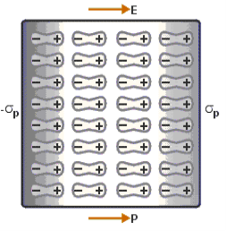
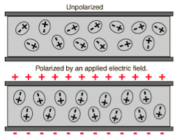
Figure 5
Above figure explains the polarisation of dielectric molecules when the electric field is applied.
Dielectric polarization occurs when a dipole moment is formed in an insulating material because of an externally applied electric field. When a current interacts with a dielectric material, the dielectric material will respond with a shift in charge distribution with the positive charges aligning with the electric field and the negative charges aligning against it.
Susceptibility is the extent to which a given material gets polarised when it is kept in an electric field.
If the material gets polarised more, it will set up an internal field which opposes the external field which will then reduce the total electric flux through that material. Therefore, electric susceptibility affects the electric permittivity of the medium.
Greater the level of polarisation, lower will be the electric permitivity
For most linear dielectric materials, the polarization P is directly proportional to the average electric field strength E so that the ratio of the two, P/E, is a constant that expresses an intrinsic property of the material.
The electric susceptibility, χe, in the centimetre-gram-second (cgs) system, is defined by this ratio; that is,
χe = P/E.
In the metre-kilogram-second (mks) system, electric susceptibility is defined slightly differently by including the constant permittivity of a vacuum, ε0, in the expression; that is,
χe = P/(ε0E).
In both systems the electric susceptibility is always a dimensionless positive number. Because of the slight difference in definition, the value of the electric susceptibility of a given material in the mks system is 4π times its value in the cgs system.
Susceptibility of polar dielectric depends upon the temperature whereas Susceptibility of non-polar dielectric is independent of the temperature.
Dielectric constant
Dielectric constant it is a quantity measuring the ability of a substance to store electrical energy in an electric field.
Or
The ratio of the permittivity of the substance to the permittivity of the free space
Dielectric constant is also called Relative Permittivity Dielectric Constant is expressed by Greek letter kappa ‘κ’. It is dimensionless quantity.
It is mathematically expressed as:
κ = 
Where,
- κ is the dielectric constant
- 𝜺 is the permittivity of the substance
- 𝜺0 is the permittivity of the free space
Dielectric constant in terms of capacitance
Dielectric constant is equal to the ratio of the capacitance of a capacitor filled with the given material to the capacitance of an identical capacitor in a vacuum without the dielectric material.
If C is the value of the capacitance of a capacitor filled with a given dielectric and C0 is the capacitance of an identical capacitor in a vacuum, the dielectric constant κ, is simply expressed as
κ = 
Dielectric Strength
It is defined as the maximum electric field which the material can sustain without breaking down.
When a high electric field is applied to the dielectric, the outer electrons get detached from their parent atoms. The dielectric then behaves as a conductor. In other words every dielectric starts conducting when if an external field is applied to it. This value of electric field depends on the nature of material of dielectric and is called dielectric strength.
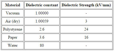
Table 1: List of value of dielctric constant and dielectric strength of some material
Relation between dielectric constant and susceptibility
Electric displacement, also known as dielectric displacement and usually denoted by D, is a vector field in a non-conducting medium, a dielectric.
In a dielectric material, the presence of an electric field E causes the bound positive and negative charges in the material to slightly separate, inducing a local electric dipole moment. The electric displacement field "D" is defined as
D= 𝜺0E+P
D =
Electric displacement
E = External electric field in which the dielectric is placed
𝜺0 = the permittivity of the free space
P = Polarization Density
In S.I. System, Unit of Electric displacement is C/m2.
D =  E+P
E+P
D=  E and P =
  eE
eE
Substituting these values in eq (1), we get
 E =
E =  E+
E+ eE
eE
 =
=  +
+ e
e
 = 1 +
= 1 + 
But
κ =  = Dielectric constant
κ = 1 + 
Clearly values of κ for all dielectric is greater than one, and for empty space  e=0 and κ =1.
"When a dielectric material placed in external electrical field , it's molecule gain electric dipole moment and dielectric said to be polarised"
"The induce moment per unit volume of dielectric material is called the electric polarization of dielectric." It is represented by vector p.
Type of dielectric polarization
There are four types of dielectric polarization
1. Electronic polarization
2. Ionic polarization
3. Orientational polarization
4. Space charge polarization
1. Electric Polarization
Electronic polarization refers to the separation of centre of positive charge and centre of negative charge in a material.This separation is caused by high electric field.
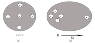
Figure 6 (a) shows thecharge distribution of an atom in absence of electric field while figure (b) Show the charge distribution in presence of external electrical field.
Let us consider a single atom of atomic number Z. +e coulomb is the charge of each proton in the nucleus and -e coulomb is the charge of each electron surrounds the nucleus. All electrons in the atom form a spherical cloud of negative charge surrounds the positively charged nucleus. The charge of nucleus is +Ze coulombs and charge of the negative cloud of electrons is -Ze coulombs.
Let us also assume that the negative charge of the electrons cloud is homogeneously distributed on a sphere of radius R. In the absence of external electric field, the center of this sphere and center of nucleus of the atom coincide.
When an external electric field E is applied to the atom. Because of this external electric field the nucleus of the atom is shifted towards negative intensity of the field and the electron cloud is shifted towards the positive intensity of the field.
As due to influence of external electric field the center of nucleus and center of electrons cloud are separated, there will be an attractive force between them according to Coulomb’s law.
Let us suppose x is distance of separation between positive charge nucleus and electron cloud.
Also, Nucleus is considered as point charge. Hence, the electrostatic force acting on the nucleus =+EZe …….(1)
As we know nucleus has been shifted from the center of electrons cloud by a distance x.
By using Gauss’s theorem
The force is only due to electron cloud acting upon nucleus would only be due to the portion of the cloud enclosed by the sphere of radius x. Portion outside the sphere of radius x does not apply any force on the nucleus.
Volume of the sphere of radius x = (4/3)πx3 and
Volume of the sphere of radius R = (4/3)πR3
Now total negative charge of the electron cloud is -Ze …..(2)
Hence, the quantity of negative charge enclosed by the sphere of radius x is,
[-Ze/(4/3)πR3] * (4/3)πx3 = -Ze (x3/ R3) ……..(3)
According to coulomb’s law = q1q2 /4 πR2
Here it becomes charge on electrons q1=-Ze (x3/ R3)
Charge on nucleus q2= Ze
So coulomb’s force = {-Ze (x3/ R3) * Ze}/4πƐox2 = Z2e2x/4πƐo R3 ……(4)
Note- magnitude is taken into account. Neglect negative sign.
i.e. At equilibrium Electrostatic force = Coulomb force .
EZe = Z2e2x/4πƐoR3 ……..(5)
Upon simplify
x = {4πƐoR3/Ze} E
Now dipole moment = either charge * separation between charges i.e. x
= Ze *{4πƐoR3/Ze} E
= 4πƐoR3E
Polarization is number of dipole moment per unit volume. Let us suppose N is the number of dipoles per unit volume so
Pe=4πƐoR3EN
So it is clear that polarization depends upon radius of atom or volume of atom and number of atoms present per unit volume.
2. Ionic polarization
Ionic polarization occurred only in that dielectric material in which atoms contain ionic bonds. When such a material is placed in an external electric field the separation between positive charge and negative charge is separated through larger distance as compared to original length.
NaCl and KCl molecule shows ionic polarization occurs. In this polarization the net electric field is zero.
Sodium chloride (NaCl) molecule is formed by ionic bond between sodium and chlorine atoms. Due to electrostatic force between positive sodium and negative chlorine ions, they bound together and form sodium chloride molecule. Because of the presence of inter nucleus distance in the sodium chloride molecule, one might think that an ionic crystal would possess polarization even in the absence external electric filed. Since each pair constitute an electric dipole. But this is not so due to lattice symmetry these dipoles cancel each other’s effect.
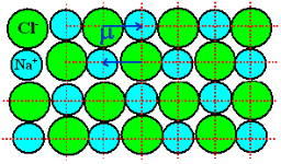
Figure 7: of NaCl crystal
As NaCl have only two atoms or ions there must be a single dipole moment pointing from negative to positive ion in each molecule. But there exists other ionic compounds having more than two atoms.
Number of dipole moments is directly proportional to the number of bonds in a molecule. But all the dipole moments are directed from relatively negative ion to positive ion. The resultant dipole moment of a single molecule would be the vector sum of individual dipole moments of the molecule.
In absence of electric field E, the distance between the ions is d but in presence of electric field, distances between the ions increases.
8 Figure of NaCl in the presence of electric field
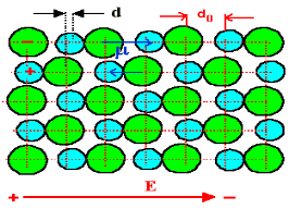
In the presence of electric field we have certain amount of dipole moment.
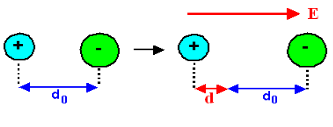
Figure 9
Hence force F1 due to electric field is
F1=qE ……(1)
Where q is the net charge on ion.
F2 restoring force due to binding force between ions
F2=kd …..(2)
Where k is spring constant. Here we are considering bond as spring.
k may also expressed in terms of other constant which is related to the shape of interatomic potential as young’s modulus or modulus of rigidity as
k=Ydo …..(3)
At Equilibrium F1 = F2 at equilibrium distance d
QE = kd
QE = Ydod using (3)
d =  qE/Ydo
Now dipole moment p= qd = q2E/Ydo …..(4)
And polarization Pi = Nq2E / Ydo ……(5)
This is called ionic polarization. This can also be expressed as
Pi =NαiE
Where αi is constant of proportionality known as ionic polarizability constant. This polarization is independent of temperature.
3. Orientational Polarization
Polar dielectric exhibit orientational polarization. In the absence of electric field, the orientation of the molecule are random and hence the net dipole moment is zero when external force is applied the dipole tried to align themselves along the direction of the applied field. This type of polarization is known as orientational polarization.
Ionic polarization: Orientational polarization: This occurs due to the permanent dipole moment in a material. It occurs in elements such as HCl and H2O.
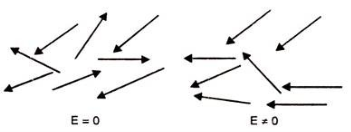
Figure 10
Potential energy U of the dipole moment making an angle θ with the electric field. Where p0 is the dipole moment.
U=−p0⋅E=−p0Ecosθ
According to statistical mechanics, the number of dipoles or molecules making an angle with the electric field is proportional to
e−U/kT
Letting n(θ) be the number of molecules per unit solid angle at θ, we have
n(θ)=n0e+p0Ecosθ/kT
For normal temperatures and fields, the exponent is small, so we can approximate by expanding the exponential:
n(θ)= n0 (1+p0EcosθkT)
To find n0 , we integrate over all angles and the result is equal to N.
Where N is the total number of molecules per unit volume. The average value of cosθ over all angles is zero, so the integral is just n0 times the total solid angle 4π. We get
n0=N4π or N= n0 /4π
There exits molecules along the field (cosθ=1) than against the field (cosθ=−1). So in any small volume containing many molecules there will be a net dipole moment per unit volume.
As dipole moment is present so polarization Pd is given
Pd =∑unitvolumep0cosθi
Evaluate Total Polarization over solid angle 2πsinθdθ. We have to integrate it
Pd = 0∫π n(θ)p0cosθ2πsinθdθ
Substitute the value of n(θ)
Pd = −N/2 −1∫1 {1+(p0E/kT)cosθ)p0cosθd(cosθ)
By integrating we get,
Pd =Np02E/ 3kT
The polarization is proportional to the field E and depends inversely on the temperature, because at higher temperatures there is more randomness by collisions.
This can also be expressed as
Pd =αdE
Where αd is called dipolar or orientation polarizability and it is equal to p02/ 3kT.
4. Space Charge Polarization
Space charge occurs due to accumulation of charge at the electrodes are at the interface in the multiphase material at shown in the figure. The ions diffuse over the appreciable distance in response to the applied field. This gives the rise of redistribution of charges in the dielectric medium
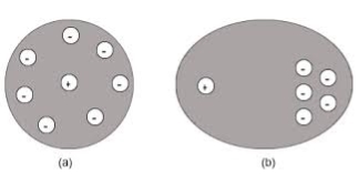
Figure 11
Space charge polarization is also known as Interfacial polarization. Space charge polarization occurs when there is an accumulation of charge at an interface between two materials or between two regions within a material because of an external field.
Space charge polarization can occur when there is a compound dielectric, or when there are two electrodes connected to a dielectric material. This type of electric polarization is different from orientational and ionic polarization because instead of affecting bound positive and negative charges i.e. ionic and covalent bonded structures, interfacial polarization also affects free charges as well.
Interfacial polarization is usually observed in amorphous or polycrystalline solids. Figure 12 shows an example of how free charges can accumulate in a field, causing interfacial polarization.
The electric field will cause a charge imbalance because of the dielectric material's insulating properties. However, the mobile charges in the dielectric will migrate over maintain charge neutrality. This then causes interfacial polarization.
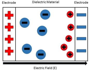
Figure 12
Figure 5: This shows how the free positive charges inside the dielectric material migrate towards the negative charge build-up on the right, caused by the external electric field.
The equation to show the space charge polarizability constant is
αc=α - α∞- α0 …………(1)
Where αc is the space charge polarizability and α, α∞, and α0 refer to the total, electronic, and orientational polarizations respectively.
It is important to note that because the charges are free charges, defects such as grain boundaries or other interfaces can serve as a medium for interfacial polarizability to form.
From the equation of space charge polarization, it is then determined that the total amount of dielectric polarization in a material is the sum of the electronic, orientational, and interfacial polarizabilities,
Or
α=αc+α∞+α0
In dielectric solids, the atoms or molecules experience not only the external applied electric field but also the electric field produced by the dipoles. The resultant electric field acting on the atoms or molecules of dielectric substance is called the local field or an internal field.
To find an expression for local electric field on a dielectric molecule or an atom, we consider a dielectric material in the electric field of intensity E, between the capacitor plates so that the material is uniformly polarized, as a result opposite type of charges are induced on the surface of the dielectric near the capacitor plates. The local field is calculated by using the method suggested by Lorentz.
According to this method,
Internal field or Local field in solids
Consider a dielectric material and is subjected to external field of intensity E1. The charges are induced on the dielectric plate and the induced electric field intensity is taken as E2. Let E3 be the field at the center of the material. E4 be the induced field due to the charges on the spherical cavity. The total internal field of the material is
 ………..(1)
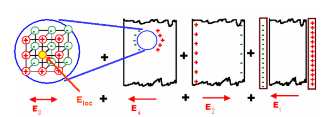
Figure 13
Now consider the Electric field intensity applied E1
 ………..(2)
We know
 ………..(3)
Substituting the Electric flux density D in E1, we get
 ………..(4)
 ………..(5)
E2 is the Electric field intensity due to induced or polarized charges
 ………..(6)
Here the charge is induced due to the induced field so the electric flux density D changes to the electric polarization P
 ………..(7)
Since we have considered that the specimen is non-polar dielectric material, at the center of the specimen the dipole moment is zero and hence the electric field intensity at the center is zero due to symmetric structure.
 ………..(8)
Now consider a circle from the center of the dielectric material. Calculation of the electric field intensity E4 on the surface of spherical cavity.
As we know the polarization P is the induced charge per unit area
 ………..(9)
Here the polarization changes to its component so we will take the component which is contributing.

 ………..(10)
Now this equation can be solved by finding out the values of the charge dq in the surface are dA. We know the Electric field intensity E
 ………..(11)
Multiplying with the cosine angle on both the sides we get
 ………..(12)
Now by applying all the present condition for the above equation we
 ………..(13)
Now substituting the charge dq in the above equation we get
 ………..(14)
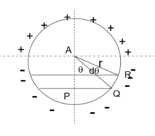
Figure 14
If dA is the surface area of the sphere of radius r lying between θ and θ+dθ is the direction with reference to the direction of the applied force, then
DA= 2π(PQ)(QR)
But
Sinθ= PQ/r,
PQ = rsinθ ………..(15)
And
dθ=QR/r,
QR=r dθ ………..(16)

Hence dA= 2πrsinθrdθ= 2πr2sinθdθ ………..(17)
Now substituting all the values in the electric field intensity on the spherical cavity E4 we get,
 ………..(18)
Substituting (17) in (18), we get

 ………..(19)
Integrating with in the limits 0 to π

 ………..(20)
On solving the integration we get,

 ………..(21)
So the total electric field

 ………..(22)
Hence the Internal field obtained is
 ………..(23)
It gives the relation between the dielectric constant and the ionic polarizability of atoms in dielectric material. If there are N number of atoms, the dipole moment per unit volume which is called Polarization is given by,
 ………..(24)
We know internal field
 ………..(25)
From above equations


 ………..(26)
We know polarization from the relation between polarization and dielectric constant
 ………..(27)
From the above two equations we get,


 ………..(28)
Dielectric materials are used in many applications such as:
- A material with high dielectric constant is widely used in semiconducting manipulating process to enhance performance and reduce device size.
- Used in Electronic components such as capacitors which is responsible for energy storage properties of the device.
- High dielectrics are frequently used in microchip IC, Transistor and microprocessor, computer etc.
- It is dielectric heating is widely used in dehydration of food and wooden sheets.
- Dielectric materials are also used in Display applications like LCD (liquid crystal displays).
- Cooking in microwave oven which one of the example of dielectric heating
- The liquid dielectric have unique property of combining insulating property with cooling ability.
- Ceramic dielectric is used in Dielectric Resonator Oscillator.
- Barium Strontium Titanate thin films are dielectric which are used in microwave tunable devices providing high tunability and low leakage current.
- Parylene is used in industrial coatings acts as a barrier between the substrate and the external environment.
- In electrical transformers, mineral oils are used as a liquid dielectric and they assist in the cooling process.
- Castor oil is used in high-voltage capacitors to increase its capacitance value.
- Electrets, a specially processed dielectric material acts as electrostatic equivalent to magnets.
The magnetic effects in magnetic materials are due to atomic magnetic dipoles in the materials. These dipoles result from effective current loops of electrons in atomic orbits, from effects of electron spin & from the magnetic moments of atomic nuclei.
The electric currents in an atom are caused by orbital and spin motions of electrons and those of its nucleus. Since all these motions of charged particles form closed electric currents, they are equivalent to “magnetic dipoles”. When such dipoles are subjected to an external electric field, they experience a torque which tends to align their magnetic moments in the direction of the externally applied field.
Some Important Definitions
Magnetic dipole
Each tiny dimension of a magnetic material (or) atoms in magnetic materials is called magnetic dipole. This magnetic dipole produces magnetic moment depending on the alignment with respect to the applied magnetic field.
Magnetic flux (Ф)
It is defined as the amount of magnetic lines of forces passing perpendicularly through unit area of a given material. It is denoted by ‘Ф’
Ф=AB
Where A= Area of cross section of the material in m2
B = magnetic Induction in Wb/ m2
Units: Weber (Wb)
Intensity of Magnetization (M)
When a material is magnetized, it develops a net magnetic moment. The magnetic moment per unit volume is called Intensity of magnetization.
Magnetization (M) = 
Units: Amp/m
Magnetic Induction (B)
Magnetic induction at a point is defined as the force experienced by a unit North Pole Placed at that point. It is denoted by ‘B’i.e.
B =
Unit is weber / m2
Magnetizing field strength (H)
When a medium is exposed to a magnetic field of intensity ‘H’, it causes an induction ‘B’ in the medium.i.e. B H
B = μH
Where μ = absolute permeability of the medium. If the medium is air or vacuum B=μ0H
μ0=permeability of free space i.e. air or vacuum
μ0=4𝜋×10-7 H/m
Units for H: Amp /m
Permeability (μ)
It indicates with which the material allows magnetic lines of force to pass through it.
Or
It is the ability of the medium to pass magnetic lines of forces through it.
There are three Permeabilities i.e. μ1,μ0, μr
μ = μ0μr
Where μ = Absolute permeability of the medium
μ0 = Permeability of free space i.e. air or vacuum
μr = Relative permeability of the medium
Magnetic moment
Magnetic moment μm = (current) × (area of circulating orbit)
μm = (I) × (𝜋r2)
Units: Amp-m2
When the magnetic dipoles (atoms consisting of charged particles like protons & neutrons) undergo orbital motion (or) spin motion produces a magnetic moment. Since motion of charged particles is considered as closed electric current loops which in turn produces a magnetic moment.
Magnetic susceptibility (χ)
If H is the applied magnetizing field intensity and M is the amount of magnetization of the material,
Then χ = 
χ = 0 in vacuum
χ = +ve for paramagnetic and Ferro magnetic materials
χ = -ve for diamagnetic materials
Units: It has no units.
We know that electric current through a conductor develops magnetic field around it or current through a coil of wire will act as a magnet. This informs that there is an intimate relation between electric current and magnetic field. Flow of electrons along a path constitute electric current.
In all atoms, electrons are revolving around the nucleus in different orbits. These revolving electrons constitute an electrical current in the orbits. These currents form magnetic dipoles. As electrons in an atom are revolving in different orbits that are randomly oriented, so the magnetic dipoles due to orbital motion of electrons are randomly oriented, results in zero magnetic dipole moment.
The magnetism of solid is originated from the electrons of atoms. Electrons are making orbital motions and spin rotations. Since an electron has a charge, magnetic moment appears just like magnetic filed is generated when current flows in solenoid coils. The magnetic moment appears even from the spin orientation of electrons. The magnetic moment generated from the orbital or spin motion of a single electron is called Bohr magnetron, which is the smallest unit of magnetic moment of solids.
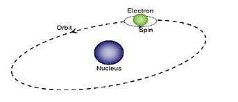
Figure 15
Although many electrons are moving by orbital motions and spin orientations around nuclei, only two electrons with up and down spins can occupy one orbit. Therefore, most of the magnetic moments originated from spins cancel each other and does not contribute to the magnetic moment of a solid.
In the case of transition elements whose d-orbit is not fully occupied and rare earth elements whose p-orbit is not fully occupied, magnetic moment appear due to the spins. According to Hand’s rule, electrons are occupied so that the total spin becomes maximum. In other words, the number of up-spins increases from 1 to 5 according to the atomic number, thereafter, total spin amount decreases as up-spin and down-spin cancel each other when two electrons occupy one orbit. The reason why the actual metal never has such a high magnetization of 5 Bohr magneton is that the d-electrons are shared by many atoms in crystals as free electron. Thus, the maximum magnetization obtained from FeCo is 2.4 Bohr magneton, which is less than half of the Bohr magneton of an atom.
Magnetic materials are classified as follows:
- Diamagnetic
- Paramagnetic
- Ferro magnetic
- Anti-Ferro magnetic
Diamagnetic
The orbital motion of electrons around the nucleus produces a magnetic field perpendicular to the plane of the orbit. Thus each electron orbit has finite orbital magnetic dipole moment. Since the orbital planes are oriented in random manner, the vector sum of magnetic moments is zero and there is no resultant magnetic moment for each atom.
In the presence of an external magnetic field, some electrons are speeded up and some are slowed down. The electrons whose moments were anti-parallel are speeded up according to Lenz’s law and this produces an induced magnetic moment in a direction opposite to the field. The induced moment disappears as soon as the external field is removed.
When placed in a non-uniform magnetic field, the interaction between induced magnetic moment and the external field creates a force which tends to move the material from stronger part to weaker part of the external field. It means that diamagnetic material is repelled by the field.
This action is called diamagnetic action and such materials are known as diamagnetic materials. Examples: Bismuth, Copper and Water etc.
The properties of diamagnetic materials are
- Magnetic susceptibility is negative.
- Relative permeability is slightly less than unity.
- The magnetic field lines are repelled or expelled by diamagnetic materials when placed in a magnetic field.
- Susceptibility is nearly temperature independent.
- Examples: Cu, Au, Zn, H20, Bi etc. organic materials
Paramagnetic materials
In some magnetic materials, each atom or molecule has net magnetic dipole moment which is the vector sum of orbital and spin magnetic moments of electrons. Due to the random orientation of these magnetic moments, the net magnetic moment of the materials is zero.
In the presence of an external magnetic field, the torque acting on the atomic dipoles will align them in the field direction. As a result, there is net magnetic dipole moment induced in the direction of the applied field. The induced dipole moment is present as long as the external field exists.
The properties of paramagnetic materials are:
- Magnetic susceptibility is positive and small.
- Relative permeability is greater than unity.
- The magnetic field lines are attracted into the paramagnetic materials when placed in a magnetic field.
- Susceptibility is inversely proportional to temperature.Ferromagnetic materials
An atom or a molecule in a ferromagnetic material possesses net magnetic dipole moment as in a paramagnetic material. A ferromagnetic material is made up of smaller regions, called ferromagnetic domain (Figure 3.27). Within each domain, the magnetic moments are spontaneously aligned in a direction. This alignment is caused by strong interaction arising from electron spin which depends on the inter-atomic distance. Each domain has net magnetisation in a direction. However the direction of magnetisation varies from domain to domain and thus net magnetisation of the specimen is zero.
In the presence of external magnetic field, two processes take place
1. the domains having magnetic moments parallel to the field grow in size
2. the other domains (not parallel to field) are rotated so that they are aligned with the field.
As a result of these mechanisms, there is a strong net magnetisation of the material in the direction of the applied field
When placed in a non-uniform magnetic field, the ferromagnetic materials will have a strong tendency to move from weaker to stronger part of the field. Materials which exhibit strong magnetism in the direction of applied field are called ferromagnetic materials. Examples: Iron, Nickel and Cobalt.
The properties of ferromagnetic materials are:
- Magnetic susceptibility is positive and large.
- Relative permeability is large.
- The magnetic field lines are strongly attracted into the ferromagnetic materials when placed in a magnetic field.
- Susceptibility is inversely proportional to temperature.
Antiferromagnetism
In the periodic table the only element exhibiting antiferromagnetism at room temperature is chromium. Antiferromagnetic materials are very similar to ferromagnetic materials but the exchange interaction between neighbouring atoms leads to the anti-parallel alignment of the atomic magnetic moments. Therefore, the magnetic field cancels out and the material appears to behave in the same way as a paramagnetic material. Like ferromagnetic materials these materials become paramagnetic above a transition temperature, known as the Neel temperature, TN. (Cr: TN=37ºC).
The properties of antiferromagnetic materials are:
- They have permanent magnetic dipoles
- They do not possess permanent magnetic dipole moment. Since in the absence of field they have no spontaneous magnetization due to anti parallel spin
- The relative permeability μr>1
- Susceptibility χ is small but negative
- 𝜒depends on temperature
Magnetic Hysteresis
The lag or delay of a magnetic material known commonly as Magnetic Hysteresis, relates to the magnetisation properties of a material by which it firstly becomes magnetised and then de-magnetised.
The set of magnetisation curves, M above represents an example of the relationship between B and H for soft-iron and steel cores but every type of core material will have its own set of magnetic hysteresis curves. You may notice that the flux density increases in proportion to the field strength until it reaches a certain value were it cannot increase any more becoming almost level and constant as the field strength continues to increase.
This is because there is a limit to the amount of flux density that can be generated by the core as all the domains in the iron are perfectly aligned. Any further increase will have no effect on the value of M, and the point on the graph where the flux density reaches its limit is called Magnetic Saturation also known as Saturation of the Core and in our simple example above the saturation point of the steel curve begins at about 3000 ampere-turns per metre.
As the magnetic field strength, ( H ) increases these molecular magnets become more and more aligned until they reach perfect alignment producing maximum flux density and any increase in the magnetic field strength due to an increase in the electrical current flowing through the coil will have little or no effect.
Retentivity
Let’s assume that we have an electromagnetic coil with a high field strength due to the current flowing through it, and that the ferromagnetic core material has reached its saturation point, maximum flux density. If we now open a switch and remove the magnetising current flowing through the coil we would expect the magnetic field around the coil to disappear as the magnetic flux reduced to zero.
However, the magnetic flux does not completely disappear as the electromagnetic core material still retains some of its magnetism even when the current has stopped flowing in the coil. This ability for a coil to retain some of its magnetism within the core after the magnetisation process has stopped is called Retentivity or remanence, while the amount of flux density still remaining in the core is called Residual Magnetism, BR .
The reason for this that some of the tiny molecular magnets do not return to a completely random pattern and still point in the direction of the original magnetising field giving them a sort of “memory”. Some ferromagnetic materials have a high retentivity (magnetically hard) making them excellent for producing permanent magnets.
While other ferromagnetic materials have low retentivity (magnetically soft) making them ideal for use in electromagnets, solenoids or relays. One way to reduce this residual flux density to zero is by reversing the direction of the current flowing through the coil, thereby making the value of H, the magnetic field strength negative. This effect is called a Coercive Force, HC .
If this reverse current is increased further the flux density will also increase in the reverse direction until the ferromagnetic core reaches saturation again but in the reverse direction from before. Reducing the magnetising current, i once again to zero will produce a similar amount of residual magnetism but in the reverse direction.
Then by constantly changing the direction of the magnetising current through the coil from a positive direction to a negative direction, as would be the case in an AC supply, a Magnetic Hysteresis loop of the ferromagnetic core can be produced.
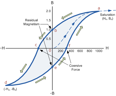
16 Figure
The B-H Curve or Magnetic Hysteresis loop above, shows the behaviour of a ferromagnetic core graphically as the relationship between B and H is non-linear.
Starting with an unmagnetised core both B and H will be at zero, point 0 on the magnetisation curve.
If the magnetisation current, i is increased in a positive direction to some value the magnetic field strength H increases linearly with i and the flux density B will also increase as shown by the curve from point 0 to point a as it heads towards saturation.
Now if the magnetising current in the coil is reduced to zero, the magnetic field circulating around the core also reduces to zero. However, the coils magnetic flux will not reach zero due to the residual magnetism present within the core and this is shown on the curve from point a to point b.
To reduce the flux density at point b to zero we need to reverse the current flowing through the coil. The magnetising force which must be applied to null the residual flux density is called a “Coercive Force”. This coercive force reverses the magnetic field re-arranging the molecular magnets until the core becomes unmagnetised at point c.
An increase in this reverse current causes the core to be magnetised in the opposite direction and increasing this magnetisation current further will cause the core to reach its saturation point but in the opposite direction, point d on the curve.
This point is symmetrical to point b. If the magnetising current is reduced again to zero the residual magnetism present in the core will be equal to the previous value but in reverse at point e.
Again reversing the magnetising current flowing through the coil this time into a positive direction will cause the magnetic flux to reach zero, point f on the curve and as before increasing the magnetisation current further in a positive direction will cause the core to reach saturation at point a.
Then the B-H curve follows the path of a-b-c-d-e-f-a as the magnetising current flowing through the coil alternates between a positive and negative value such as the cycle of an AC voltage. This path is called a B-H Curve or Magnetic Hysteresis Loop.
The effect of magnetic hysteresis shows that the magnetisation process of a ferromagnetic core and therefore the flux density depends on which part of the curve the ferromagnetic core is magnetised on as this depends upon the circuits past history giving the core a form of “memory”. Then ferromagnetic materials have memory because they remain magnetised after the external magnetic field has been removed.
However, soft ferromagnetic materials such as iron or silicon steel have very narrow magnetic hysteresis loops resulting in very small amounts of residual magnetism making them ideal for use in relays, solenoids and transformers as they can be easily magnetised and demagnetised.
Since a coercive force must be applied to overcome this residual magnetism, work must be done in closing the hysteresis loop with the energy being used being dissipated as heat in the magnetic material. This heat is known as hysteresis loss, the amount of loss depends on the material’s value of coercive force.
By adding additive’s to the iron metal such as silicon, materials with a very small coercive force can be made that have a very narrow hysteresis loop. Materials with narrow hysteresis loops are easily magnetised and demagnetised and known as soft magnetic materials.
Magnetic Hysteresis Loops for Soft and Hard Materials
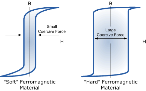
Figure 17
Magnetic Hysteresis results in the dissipation of wasted energy in the form of heat with the energy wasted being in proportion to the area of the magnetic hysteresis loop. Hysteresis losses will always be a problem in AC transformers where the current is constantly changing direction and thus the magnetic poles in the core will cause losses because they constantly reverse direction.
Rotating coils in DC machines will also incur hysteresis losses as they are alternately passing north the south magnetic poles. As said previously, the shape of the hysteresis loop depends upon the nature of the iron or steel used and in the case of iron which is subjected to massive reversals of magnetism, for example transformer cores, it is important that the B-H hysteresis loop is as small as possible.
Ferrites are ferromagnetic material containing predominantly oxides iron along with other oxides of barium, strontium, manganese, nickel, zinc, lithium and cadmium.
Ferrimagnetism is only observed in compounds, which have more complex crystal structures than pure elements. Within these materials the exchange interactions lead to parallel alignment of atoms in some of the crystal sites and anti-parallel alignment of others. The material breaks down into magnetic domains, just like a ferromagnetic material and the magnetic behaviour is also very similar, although ferrimagnetic materials usually have lower saturation magnetisations. For example in Barium ferrite (BaO.6Fe2O3) the unit cell contains 64 ions of which the barium and oxygen ions have no magnetic moment, 16 Fe3+ ions have moments aligned parallel and 8 Fe3+ aligned anti-parallel giving a net magnetisation parallel to the applied field, but with a relatively low magnitude as only ⅛ of the ions contribute to the magnetisation of the material.
At high frequency metallic soft magnetic materials simply cannot be used due to the eddy current losses. Therefore, soft ferrites, which are ceramic insulators, become the most desirable material. These materials are ferrimagnetic with a cubic crystal structure and the general composition MO.Fe2O3, where M is a transition metal such as nickel, manganese or zinc.
MnZn ferrite, sold commercially as ferroxcube, can be used at frequencies up to 10MHz, for example in telephone signal transmitters and receivers and in switch mode power supplies (also referred to as DC-DC converters). For this type of application the driving force to increase frequency is to allow miniaturisation. Additionally, part of the family of soft ferrites, are the microwave ferrites, e.g. Yttrium iron garnet. These ferrites are used in the frequency range from 100MHz to 500GHz, for waveguides for electromagnetic radiation and in microwave devices such as phase shifters.
Garnet ferrites have the structure of the silicate mineral garnet and the chemical formula M3(Fe5O12), where M is yttrium or a rare-earth ion. In addition to tetrahedral and octahedral sites, such as those seen in spinels, garnets have dodecahedral (12-coordinated) sites. The net ferrimagnetism is thus a complex result of antiparallel spin alignment among the three types of sites. Garnets are also magnetically hard.
The properties of ferrites materials are:
- They have permanent magnetic dipoles.
- They possess permanent magnetic diploe moment. Also in the absence of field they have spontaneous magnetization. Since spin is anti-parallel but of different magnitudes
- The relative permeability μr>>1
- Susceptibility is large and positive
- 𝜒 depend on temperature
APPLICATIONS
Ferrites are ideally suited for making device like inductor core, circulators, and memory devices and also for various microwave application.
The earliest ferrite was naturally occurring magnetite. The first application of ferrites were needles magnetized by the magnetite which functioned as compasses and allowed mariners to find North without the use of the stars. .However, magnetite was found to have poor magnetic properties and was not useful for magnetic applications.
The first large-scale applications for ferrites were in the television industry where large tonnages were used for the TV tube deflection yokes and the high voltage fly back transformers.
These are used in radar, satellite communications, memory and computer applications, there has been corresponding growth in consumer markets in radio, television, video tape recorders and finally, the internet.
As the markets have changed, the requirements of ferrites have changed as well. From the old analog circuits to the newer digital ones, there arose the need for high frequency switched mode power supplies to power computers and other digital devices. Another strong market for ferrites is in the automotive industry and most recently in hybrid cars.