UNIT – III
ELECTROMAGNETIC WAVES AND FIBER OPTICS
DIVERGENCE OF ELECTROSTATIC FIELD
The electric field can be graphically represented using field lines. The direction of the field lines indicates the direction in which a positive test charge moves when placed in this field. The density of field lines per unit area is proportional to the strength of the electric field. Field lines originate on positive charges and terminate on negative charges. Field lines can never cross since if this would occur, the direction of the electric field at that particular point would be undefined. Examples of field lines produced by positive point charges are shown in Figure
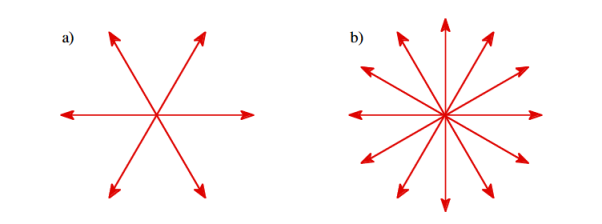
1 Figure: a) Electric field lines generated by a positive point charge with charge q. b) Electric field lines generated by a positive point charge with charge 2q.
The flux of electric field lines through any surface is proportional to the number of field lines passing through that surface. Consider for example a point charge q located at the origin. The electric flux  E through a sphere of radius r, centered on the origin, is equal to
 E = surface

Since the number of field lines generated by the charge q depends only on the magnitude of the charge, any arbitrarily shaped surface that encloses q will intercept the same number of field lines. Therefore the electric flux through any surface that encloses the charge q is equal to q/ 0.Using the principle of superposition we can extend our conclusion easily to systems containing more than one point charge:
 E = surface
  =
=  =
= 
We thus conclude that for an arbitrary surface and arbitrary charge distribution
 E = surface
  =
= 
Where Qenclosed is the total charge enclosed by the surface. This is called Gauss's law. Since this equation involves an integral it is also called Gauss's law in integral form. Using the divergence theorem the electric flux  E can be rewritten as
 E = surface
  =
=  d
d
We can also rewrite the enclosed charge Qencl in terms of the charge density ρ
 =
= d
d
Gauss's law can thus be rewritten as
 d
d =
= 
 d
d
Since we have not made any assumptions about the integration volume this equation must hold for any volume. This requires that the integrands are equal:
 =
= 
This equation is called Gauss's law in differential form.
This is the required expression for divergence of electric field.
Divergence is the outflow of flux from a small closed surface area (per unit volume) as volume shrinks to zero.
Physical Interpretation of the Divergence
For an electric field:∇·E= ρ/ε, that is there are sources of electric field. Consider a vector field F that represents a fluid velocity: The divergence of F at a point in a fluid is a measure of the rate at which the fluid is flowing away from or towards that point.
A positive divergence is indicating a flow away from the point. ƒPhysically divergence means that either the fluid is expanding or that fluid is being supplied by a source external to the field. ƒ The lines of flow diverge from a source and converge to a sink.
If there is no gain or loss of fluid anywhere then div F= 0. Such a vector field is said to be solenoidal.
Air leaving a punctured tire: Divergence is positive, as closed surface (tire) exhibits net outflow.
CURL OF ELECTROSTATIC FIELD
For a point charge q placing at the origin, the electric field is:
E = 

The curl calculation by integration:
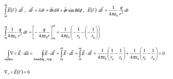
By superposition rule:
 =
=  +
+ +
+ +
+ +…………
+…………
 =
= 
 +
+ 
 +………=0
The curl calculation by differentiation:

Physical Interpretation of the Curlƒ
Consider a vector field F that represents a fluid velocity:
The curl of F at a point in a fluid is a measure of the rotation of the fluid.
If there is no rotation of fluid anywhere then ∇x F= 0. Such a vector field is said to be irrotational or conservative.
An electrostatic field (denoted by E) has the property ∇xE= 0, an irrotational (conservative) field.
DIVERGENCE AND CURL OF STATIC MAGNETIC FIELD
The static electric field E(x; y; z) such as the field of static charges obeys equations
∇. E = ρ ………..(3.2a)
 = 0 ………..(3.2b)
The static magnetic field B(x; y; z) such as the field of steady currents obeys different equations
 =0 ………..(3.2c)
 J ………..(3.2d)
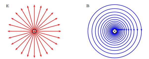
Figure 2
Due to this difference, the magnetic field of long straight wire looks quite different from the electric field of a point charge or a linear charge.
Later in these notes we will derive equations (3.2c) and (3.2d) from the Biot Savart Law.
Let us explore some of their consequences. The zero-divergence equation (3.2c) is valid for any magnetic field, even if it is time-dependent rather than static. Physically, it means that there are no magnetic charges, otherwise we would have ∇.B  mag instead of ∇ B= 0.
Consequently, the magnetic field lines never begin or end anywhere in space; instead they form closed loops or run from in infinity to in infinity.
The integral form of eq. (3.2c) follows by the Gauss theorem: the magnetic flux through any closed surface is zero

Consequently, any open surfaces S1,S2,……..spanning the same loop L have the same magnetic flux through them, for example
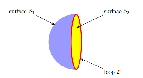
Figure 3
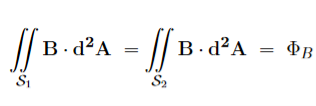
We shall this identity very useful for stating the Faraday's Law of magnetic induction.
Now consider the curl equation
 J
J
Which is the differential form of the Ampere's Law. The integral form of the Ampere's Law obtains by the Stokes' theorem: For any closed loop L and any surface S spanning that loop,

………..(3.2e)
Where Inet [through L] is the net electric current flowing through the loop L. The integral form (3.2e) of the Ampere's Law is particularly convenient when the current flows through a wire or several wires; in this case all we need is to check which wire goes through the loop L and which does not, then add up the currents in the wires that do go through L and mind their directions. But it is also convenient for the volume currents flowing through thick conductors or for current sheets flowing on surfaces.
As we know that the Ampere's Law applies only to the magnetic fields of steady currents. Otherwise, we need to use the more general Maxwell {Ampere Law, with an extra term for the time-dependent electric field.
For simplicity we say that the original Ampere's Law is simply mathematically inconsistent unless the electric current has zero divergence, ∇J= 0.Indeed, the left hand side of the curl equation  J always have zero divergence.
∇. ( ) = 0
) = 0
So we cannot have ( ) =
) =  J unless the RHS has zero divergence as well,
∇.J= 0. As to the integral form (3.2e) of the Ampere's Law, we need a divergence-less current density J to make sure that the net current through the loop L is the same for any surface S spanning the loop; otherwise we simply cannot de ne the net current through L
Maxwell equations are of fundamental importance since they describe the whole of classical electromagnetic phenomena.
From a classical perspective, light can be described as waves of electromagnetic radiation. As such, Maxwell equations are very useful to illustrate a number of the characteristics of light including polarization.
We are just to stating these equations without derivation. Since our goal is simply to apply them, the usual approach will be followed.
Maxwell’s four equations are given by
∇·E = ρ/ε0 (1)
∇×E = −∂B/∂t (2)
∇×H = J + ∂D/∂t (3)
∇·B = 0 (4)
These equations illustrate the unique coexistence in nature of the electric field and the magnetic field. The first two equations give the value of the given flux through a closed surface, and the second two equations give the value of a line integral around a loop. In this notation,
∇=(∂/∂x, ∂/∂y, ∂/∂z)
E is the electric vector
B is the magnetic induction
ρ is the electric charge density
j is the electric current density
ε0 is the permittivity of free space
c is the speed of light.
In addition to Maxwell equations, the following identities are useful:
J = σE (5)
D = εE (6)
B = μH (7)
Here,
D is the electric displacement
H is the magnetic vector
σ is the specific conductivity
ε is the dielectric constant (or permittivity)
μ is the magnetic permeability
In the Gaussian systems of units, Maxwell equations are given in the form of
∇·B=0 (8)
∇·E=4πρ (9)
∇×H=(1/c)(∂D/∂t+4πj) (10)
∇×E=−(1/c)(∂B/∂t) (11)
Free space or non-conducting medium. We know that non conducting medium means no current. So, conductivity is zero i.e. σ=0
So current density J=σE will also become zero as σ=0 Also free space means no charges which leads to ρ=0. These points mentioned below.
(a) No condition current i.e σ=0, thus J=0 ( J=σE)
(b) No charges (i.e ρ=0)
For the case of no charges or currents, that is, j = 0 and ρ = 0, and a homogeneous medium. Using these the Maxwell equation can rewritten as
∇.D=0 or ∇.E=0 as ρ=0 (12)
∇ x E= -dB/dt or ∇ x E= -μ dH/dt because B = μH (13)
∇ x H=d D/dt or ∇ x H = ε dE/dt (J=0) and D = εE (14)
∇.B=0 (15)
Now taking curl of second Maxwell’s equation (13) ,we get
∇ x(∇ x E)=- μ d/dt (∇ x H)
Applying standard vector identity, that is [∇ *(∇*E)=∇(∇.E)-∇2E] on left hand side of above equation, we get
∇ (∇ .E)-∇2E= -μ d/dt (∇ x H) (16)
Substituting equations (13) and (14) in equations (16) ,we get
-∇2E= – με d/dt (dE/dt)
Or ∇2E=με d 2 E/dT2 (17)
Equation (17) is the required wave equation in terms of electric field intensity, E for free space. This is the law that E must obey.
WAVE EQUATION IN TERMS OF MAGNETIC FIELD INTENSITY, H
Take curl of fourth Maxwell’s equation(14) ,we get
∇x(∇xH)=ε d/dt(∇xE)
Applying standard vector identity that is
[∇*(∇*H)=∇ (∇.H)-∇2H]
On left side of above equation, we get
∇(∇.H)-∇2H= ε d/dt(∇xE) (18)
Substituting equations (14) and (13) in equation (18), we get
-∇2H= – μεd/dt(dH/dt)
Or
∇2H=με d2H/dt2 (19)
Equations (19) is the required wave equation in terms of magnetic field intensity, H and this is the law that H must obey
For vacuum μ=μ0 and ε=ε0, equations (17) and (19) will become
∇2 E=μ0ε0 d2E/dt2 (20)
And ∇2H= μ0ε0 d2H/dt2 (21)
This leads to an expression for the velocity of propagation
From equation both equations (20) and (21) have the form of the general wave equation for a wave

(x,t) traveling in the x direction with speed v. Equating the speed with the coefficients, we derive the speed of electric and magnetic waves, which is a constant that we symbolize with “c”
It is useful to note that in vacuum
c2=1/ε0μ0
Where μ0 is the permeability of free space

OPTICAL FIBRE
A cable which is used to transmit the data through fibres (threads) or plastic (glass) is known as optical fibre cable. This cable includes a pack of glass threads which transmits modulated messages over light waves.
CHARACTERISTICS OF OPTICAL FIBRE
- It has a large bandwidth.
- The optical frequency of 2 x 10¹⁴ Hz can be used and hence the system has higher bandwidth.
- Thus, optical fibres have greater information-carrying capacity due to greater bandwidth.
- In optical fibre system transmission losses are as low as 0.1 db/km.
- Optical fibre is of small size and light weight as compared to electrical fibre.
- Optical fibre communication is free from electromagnetic interference.
- Optical fibre does not carry high voltage and current hence they are safer than electrical cable.
- Optical Fibres are flexible and have high tensile strength. Thus can be bent or twisted easily.
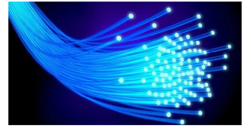
Figure 4: Optical Fibre
CONSTRUCTION OF OPTICAL FIBRE
It consists of a very thin fibre of silica or glass or plastic of a high refractive index called the core. The core has a diameter of 10 um to 100 um. The core is enclosed by a cover of glass or plastic called cladding. The refractive index of the cladding is less than that of the core (which is a must condition for the working of the optical fibre). The difference between the two indicates is very small of order 10-3. The core and the cladding are enclosed in an outer protective jacket made of plastic to provide strength to the optical fibre. The refractive index can change from core to cladding abruptly (as in step-index fibre) or gradually (as in graded-index fibre).
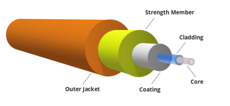
Figure 5: Representation of Optical Fibre
WORKING OF OPTICAL FIBRE
When a ray of light is incident on the core of the optical fibre at a small angle, it suffers refraction and strikes the core-cladding interface, As the diameter of the fibre is very small hence the angle of incidence is greater than the critical angle. Therefore, the ray suffers total internal reflection at the core-cladding interface and strikes the opposite interface. At this interface also, the angle of incidence is greater than the critical angle, so it again suffers total internal reflection. Thus, the ray of light reaches the other end of the fibre after suffering repeated total internal reflections along the length of the fibre. At the other end, the ray suffers refraction and emerges out the optical fibre.
We can see that the light travels in the core in a guided manner. Hence the communication through the optical fibre is sometimes referred as an optical waveguide.
Principle: Optical Fibre works on the principle of Total Internal Reflection.
Total internal reflection-
When the light ray travels from denser medium to rarer medium the refracted ray bends away from the normal. When the angle of incidence is greater than the critical angle, the refracted ray again reflects into the same medium. This phenomenon is called total internal reflection. The refracted ray bends towards the normal as the ray travels from rarer medium to denser medium. The refracted ray bends away from the normal as it travels from denser medium to rarer medium.
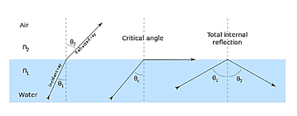
Figure 6 – Total Internal Reflection
When light passes from a medium with one index of refraction (m1), to another medium with a lower index of refraction (m2), it bends or refracts away from an imaginary line perpendicular to the surface (normal line). As the angle of the beam through m1 becomes greater with respect to the normal line, the refracted light through m2 bends further away from the line.
At one particular angle (critical angle), the refracted light will not go into m2, but instead will travel along the surface between the two media (sine [critical angle] = n2/n1 where n1 and n2 are the indices of refraction [n1 is greater than n2]). If the beam through m1 is greater than the critical angle, then the refracted beam will be reflected entirely back into m1 (total internal reflection), even though m2 may be transparent.
In physics, the critical angle is described with respect to the normal line. In fiber optics, the critical angle is described with respect to the parallel axis running down the middle of the fiber. Therefore, the fiber-optic critical angle = (90 degrees - physics critical angle).
In an optical fiber, the light travels through the core (m1, high index of refraction) by constantly reflecting from the cladding (m2, lower index of refraction) because the angle of the light is always greater than the critical angle. Light reflects from the cladding no matter what angle the fiber itself gets bent at, even if it's a full circle.
Because the cladding does not absorb any light from the core, the light wave can travel great distances. However, some of the light signal degrades within the fiber, mostly due to impurities in the glass. The extent that the signal degrades depends upon the purity of the glass and the wavelength of the transmitted light
When the angle of incidence (θ1) is progressively increased, there will be progressive increase of refractive angle (θ2). At some condition (θ1) the refractive angle (θ2) becomes 90o to the normal. When this happens the refracted light ray travels along the interface. The angle of incidence (θ1) at the point at which the refractive angle (θ1) becomes 90 degree is called the critical angle.
It is denoted by θc. The critical angle is defined as the minimum angle of incidence (θ1) at which the ray strikes the interface of two media and causes an angle of refraction (θ2) equal to 90o. Figure 6 shows critical angle refraction
Hence at critical angle θ1= θc and θ2= 90o .
Using Snell‘s law: n1 sin θ1 = n2 sin θ2
n1 sin θc = n2 sin90o
Sin θc = n2 / n1
θc = sin-1 (n2 / n1)
The actual value of critical angle is dependent upon combination of materials present on each side of boundary.
ACCEPTANCE ANGLE
Definition- Acceptance angle is defined as the maximum angle of incidence at the interface of air medium and core medium for which the light ray enters in the core and travels along the interface of core and cladding.
Let n0 be the refractive indices of air
n1 be the refractive indices of core
n2 be the refractive indices of cladding
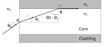
Figure 7
Let a light ray OA is incident on the interface of air medium and core medium with an angle of incidence θ0
The light ray refracts into the core medium with an angle of refraction θ1 and the refracted ray AB is again incidenting on the interface of core and cladding with an angle of incident (90- θ1)
If (90- θ1) is equal to the critical angle of core and cladding media then the ray travels along the interface of core and cladding along the path BC. If the angle of incident at the interface of air and core θ1< θ0 then (90- θ1) will be greater than the critical angle. Therefore,
The total internal reflection takes place.
According to Snell’s law at point A
n0 Sin θ0 = n1 Sin θ1
Sin θ0= (n1 / n0) Sin θ1 ………(1)
According to Snell’s law at point B
n1 Sin(90- θ1) = n2 Sin90 ………(2)
n1 Cosθ1 = n2 as (Sin90=1)
Cosθ1 = n2 /n1
Sinθ1 = (1-Cos2 θ1)1/2
Sinθ1= (1- (n2 /n1)2)1/2
Sinθ1= ( n12- n22 )1/2/ n1 ………(3)
We know Sin θ0= (n1 / n0) Sin θ1 from equation (1)
Substitute the value of Sinθ1 from equation (3)
Sinθ0= (n1 / n0) *( n12- n22 )1/2/ n1
On simplification
Sinθ0= ( n12- n22 )1/2/ n0
θ0=Sin-1 ( n12- n22 )1/2/ n0
Acceptance Angle is θ0=Sin-1 ( n12- n22 )1/2/ n0 ………(4)
NUMERICAL APERTURE
Definition: -Numerical aperture is defined as the light gathering capacity of an optical fibre and it is directly proportional to the acceptance angle. Numerically it is equal to the sin of the acceptance angle.
NA = Sin(acceptance angle)
NA = Sin {Sin-1 (( n12- n22 )1/2/ n0)} from equation (4)
NA = (( n12- n22 )1/2/ n0) ………(5)
If the refractive index of the air medium is unity i.e. n0=1 put in (5)
NA = ( n12- n22 )1/2 ………(6)
Fractional change in refractive index
∆= (n1- n2)/ n1
n1∆ = (n1- n2) ………(7)
From equation (6), we have
NA = {( n1- n2 )( n1+n2 )}1/2
NA = { n1∆ (n1+n2 )}1/2 as n1∆ = (n1- n2) by Eq(7)
NA = { n1∆ 2n1}1/2 n1 ≈ n2, so n1+n2 =2n1
NA = n1{2∆}1/2
This gives the relation between Numerical aperture and Fractional change in refractive index.
The types of optical fibres depend on the refractive index, materials used, and mode of propagation of light.
The classification based on the materials used is as follows:
- Plastic Optical Fibres: The polymethylmethacrylate is used as a core material for the transmission of the light.
Example:
Core: polymethyl methacrylate: Cladding: Co- Polymer
Core: Polystyrene: Cladding: Methyl methacrylate
- Glass Fibres: It consists of extremely fine glass fibres.
Example:
Core: SiO2 Cladding: SiO2
Core: GeO2- SiO2 Cladding: SiO2
The classification based on the mode of propagation of light is as follows:
Mode of propagation:
Light propagates as electromagnetic waves through an optical fibre. All waves, having ray directions above the critical angle will be trapped within the fibre due to total internal reflection. However, all such waves do not propagate through the fibre. Only certain ray directions are allowed to propagate. The allowed directions correspond to the modes of the fibre. In simple terms, modes can be visualized as the possible number of paths of light in an optical fibre.
- Single-Mode Fibres:
These fibres are used for long-distance transmission of signals. In general, the single mode fibres are step – index fibres. These types of fibres are made from doped silica. It has a very small core diameter so that it can allow only one mode of propagation and hence called single mode fibres.
The cladding diameter must be very large compared to the core diameter. Thus in the case of single mode fibre, the optical loss is very much reduced. The structure of a single mode fibre is given below.
Structure:
Core diameter : 5-10μm
Cladding diameter : Generally around 125μm
Protective layer : 250 to 1000μm
Numerical aperture : 0.08 to 0.10
Band width : More than 50MHz km.
Application:
Because of high bandwidth, they are used in long haul communication systems.
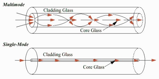
Figure 8
- Multimode Fibres:
These fibres are used for short-distance transmission of signals. The multi-mode fibres are useful in manufacturing both for step – index and graded index fibres. The multi-mode fibres are made by multi-component glass compounds such as Glass – Clad Glass, Silica – Clad – Silica, doped silica etc. Here the core diameter is very large compared to single mode fibres, so that it can allow many modes to propagate through it and hence called as Multi mode fibres. The cladding diameter is also larger than the diameter of the single mode fibres. The structure of the multimode fibre is as shown in the figure above.
Structure:
Core diameter : 50-350μm
Cladding diameter : 125μm - 500μm
Protective layer : 250 to 1100μm
Numerical aperture : 0.12 to 0.5
Band width : Less than 50MHz km.
The total number of modes possible for such an electromagnetic wave guide is
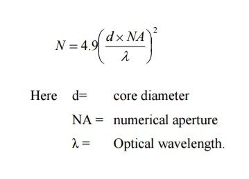
Application:
Because of its less band width it is very useful in short haul communication systems.
The classification based on the refractive index is as follows:
- Step Index Single mode Fibres
It consists of a core surrounded by the cladding, which has a single uniform index of refraction. Step index-single mode fibres: A single mode step index fibre consists of a very thin core of uniform refractive index surrounded by a cladding of refractive index lower than that of core. The refractive index abruptly changes at the core cladding boundary. Light travels along a side path, i.e., along the axis only. So zero order modes is supported by Single Mode Fibre.
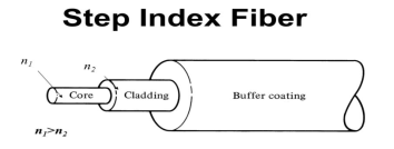
Figure 9
- Step index-Multimode fibres
A multimode step index fibre consists of a core of uniform refractive index surrounded by cladding of refractive index lower than that of the core. The refractive index abruptly changes at the core cladding boundary. The core is of large diameter. Light follows zigzag paths inside the fibre. Many such zigzag paths of propagation are permitted in Multi-Mode Fibre. The Numerical Aperture of a Multi-mode fibre is larger as the core diameter of the fibre is larger
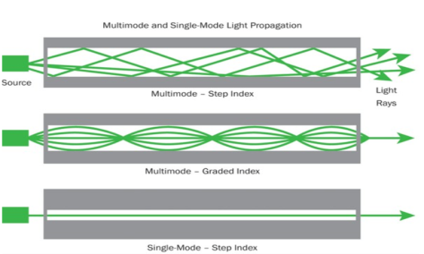
Figure 10
- Graded Index Fibres:
The refractive index of the optical fibre decreases as the radial distance from the fibre axis increases. GRIN fibre is one in which refractive index varies radially, decreasing continuously in a parabolic manner from the maximum value of n1, at the center of the core to a constant value of n2 at the core cladding interface.
In graded index fibre, light rays travel at different speeds in different parts of the fibre because the refractive index varies throughout the fibre. Near the outer edge, the refractive index is lower. As a result, rays near the outer edge travel faster than the rays at the center of the core. Because of this, rays arrive at the end of the fibre at approximately the same time. In effect light rays arrive at the end of the fibre are continuously refocused as they travel down the fibre. All rays take the same amount of time in traversing the fibre. This leads to small pulse dispersion.
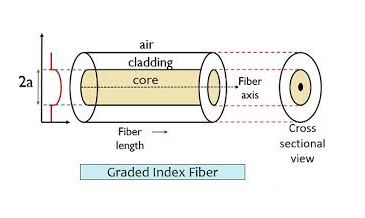
Figure 11

For a parabolic index fibre, the pulse dispersion is reduced by a factor of about 200 in comparison to step index fibre. It is because of this reason that first and second generation optical communication systems used near parabolic index fibres.
Light propagates inside an optical fiber by virtue of multiple TIRs at the core-cladding interface. The refractive index of the core glass is greater than that of the cladding. This meets the first condition for a TIR. All the light energy that is launched into the optical fiber through its tip does not get guided along the fiber. Only those light rays propagate through the fiber which is launched into the fiber at such an angle that the refracted ray inside the core of the optical fiber is incident on the core-cladding interface at an angle greater than the critical angle of the core with respect to the cladding.
1. Optical fiber is basically a solid glass rod. The diameter of rod is so small that it looks like a fiber.
2. Optical fiber is a dielectric waveguide. The light travels like an electromagnetic wave inside the waveguide. The dielectric waveguide is different from a metallic waveguide which is used at microwave and millimeter wave frequencies.
3. In a metallic waveguide, there is a complete shielding of electromagnetic radiation but in an optical fiber the electromagnetic radiation is not just confined inside the fiber but also extends outside the fiber.
4. The light gets guided inside the structure, through the basic phenomenon of total internal reflection.
5. The optical fiber consists of two concentric cylinders; the inside solid cylinder is called the core and the surrounding shell is called the cladding. (See Fig 12)
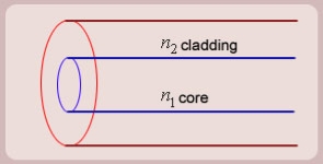
Figure12: Schematic of an optical fiber
6. For the light to propagate inside the fiber through total internal reflections at core-cladding interface, the refractive index of the core must be greater than the refractive index of the cladding. That is  .
.
SIMPLE RAY MODEL

Figure 13 (optical fiber with core, cladding and total internally reflected ray)
For propagation of light inside the core there are two possibilities.
1. A light ray is launched in a plane containing the axis of the fiber. We can then see the light ray after total internal reflection travels in the same plane i.e., the ray is confined to the plane in which it was launched and never leave the plane. In this situation the rays will always cross the axis of the fiber. These are called the Meridional rays. (Figure 13)
2. The other possibility is that the ray is not launched in a plane containing the axis of the fiber.
For example- If the ray is launched at some angle such that it does not intersect the axis of the fiber, then after total internal reflection it will go to some other plane. We can see that in this situation the ray will never intersect the axis of the fiber. The ray essentially will spiral around the axis of fiber. These rays are called the Skew rays.
So, it can be concluded that if the light is to propagate inside an optical fiber it could be through two types of rays
a) Meridional rays: The rays which always pass through the axis of fiber giving high optical intensity at the center of the core of the fiber.
b) Skew Rays: The rays which never intersect the axis of the fiber, giving low optical intensity at the center and high intensity towards the rim of the fiber.
Propagation of Meridional Rays

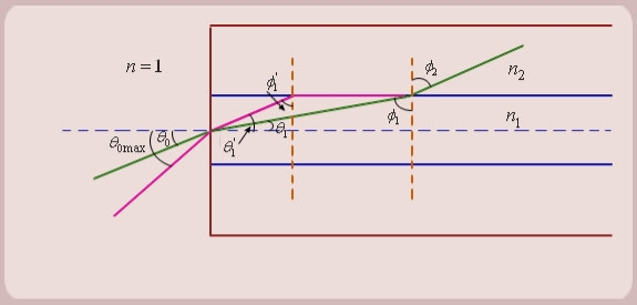 Figure 14
- Let us consider figure 14. A ray is launched from outside (air) at an angle θ0 , from the axis of the fiber.
The question is, under what conditions the ray is ultimately guided inside the core due to total internal reflections at the core cladding boundary.
2. Let the ray makes an angle θ1 with the axis of the fiber inside the core, and let the ray make an angle ϕ1 with core -cladding interface. Let ϕ2 be the angle of refraction in the cladding.
If ϕ1 < critical angle the ray is refracted in cladding. The ray which goes to cladding is lost and is not useful for communication. The ray which is confined to the core is useful for optical communication.
3. Now as we increase the launching angle θ0, the angle θ1 also increases. Since θ1 + ϕ1 = 
ϕ1 decreases and at some point becomes less than the critical angle. When ϕ1 equals the critical angle, ϕ2 equals  . The maximum launching angle then corresponds to ϕ2 =
 .
.
4. Let us apply Snell’s law at the launching point and at the core-cladding interface for the maximum launching angle θ0max. For this case let θ1 = θ’1 and ϕ1 = ϕ’1
We then have
 (since
  )
)

Now,

So, the sine of the maximum angle at which the ray will be guided inside the fiber is given by square root of the difference of squares of the refractive indices of the core and cladding. The quantity is called the numerical aperture of an optical fiber. The NA is a measure of the power launching efficiently of an optical fiber.
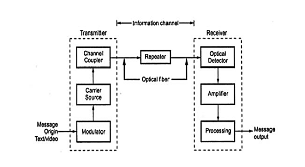
Figure 15: Block Diagram of Optical Fiber Communication System
- Message origin
Generally, message origin is from a transducer that converts a non-electrical message into an electrical signal. Common examples include microphones for converting sound waves into currents and video (TV) cameras for converting images into current. For data transfer between computers, the message is already in electrical form.
2. Modulator
The modulator has two main functions.
a) It converts the electrical message into the proper format.
b) It impresses this signal onto the wave generated by the carrier source.
c) Two distinct categories of modulation are used i.e. analog modulation and digital modulation.
3. Carrier source
Carrier source generates the wave on which the information is transmitted. This wave is called the carrier. For fiber optic system, a laser diode (LD) or a light emitting diode (LED) is used. They can be called as optic oscillators; they provide stable, single frequency waves with sufficient power for long distance propagation.
4. Channel coupler
Coupler feeds the power into the information channel. For an atmospheric optic system, the channel coupler is a lens used for collimating the light emitted by the source and directing this light towards the receiver. The coupler must efficiently transfer the modulated light beam from the source to the optic fiber. The channel coupler design is an important part of fiber system because of possibility of high losses.
5. Information channel
The information channel is the path between the transmitter and receiver. In fiber optic communications, a glass or plastic fiber is the channel. Desirable characteristics of the information channel include low attenuation and large light acceptance cone angle. Optical amplifiers boost the power levels of weak signals. Amplifiers are needed in very long links to provide sufficient power to the receiver. Repeaters can be used only for digital systems. They convert weak and distorted optical signals to electrical ones and then regenerate the original digital pulse trains for further transmission.
Another important property of the information channel is the propagation time of the waves travelling along it. A signal propagating along a fiber normally contains a range of optic frequencies and divides its power along several ray paths. This results in a distortion of the propagating signal. In a digital system, this distortion appears as a spreading and deforming of the pulses. The spreading is so great that adjacent pulses begin to overlap and become unrecognizable as separate bits of information.
6. Optical detector
The information being transmitted is detector. In the fiber system the optic wave is converted into an electric current by a photo detector. The current developed by the detector is proportional to the power in the incident optic wave. Detector output current contains the transmitted information. This detector output is then filtered to remove the constant bias and then amplified. The important properties of photo detectors are small size, economy, long life, low power consumption, high sensitivity to optic signals and fast response to quick variations in the optic power.
7. Signal processing
Signal processing includes filtering, amplification. Proper filtering maximizes the ratio of signal to unwanted power. For a digital system decision circuit is an additional block. The bit error rate (BER) should be very small for quality communications.
8. Message output
The electrical forms of the message emerging from the signal processor are transformed into a sound wave or visual image. Sometimes these signals are directly usable when computers or other machines are connected through a fiber system.
ADVANTAGES OF FIBRE OPTIC COMMUNICATION
The optical fibre communication has more advantages than convectional communication.
1. Enormous Bandwidth
2. Low Transmission Loss
ADVANTAGES OF FIBRE OPTIC COMMUNICATION
The optical fibre communication has more advantages than convectional communication.
1. Enormous Bandwidth
2. Low Transmission Loss
3. Electric Isolation
4. Signal Security
5. Small Size and Less Weight
6. Immunity Cross Talk
1. Enormous bandwidth - The information carrying capacity of a transmission system is directly proportional to the frequency of the transmitted signals. In the coaxial cable transmission the bandwidth range is up to around 500MHz only. Whereas in optical fibre communication, the bandwidth range is large as 105 GHZ.
2. Low transmission loss - The transmission loss is very low in optical fibres (i.e.KmdB/2.0) than compare with the conventional communication system. Hence for long distance communication fibres are preferred.
3. Electric isolation- Since fibre optic materials are insulators, they do not exhibit earth and interface problems. Hence communicate through fibre even in electrically danger environment.
4. Signal security- The transmitted signal through the fibre does not radiate, unlike the copper cables, a transmitted signal cannot be drawn from fibre without tampering it. Thus, the optical fibre communication provides 100% signal security.
5. Small size and less weight - The size of the fibre ranges from 10μm to 50μm, which is very small. The space occupied by the fibre cable is negligibly small compared to conventional electrical cables. Optical fibres are light in weight.
6. Immunity cross talk - Since the optical fibres are dielectric wave guides, they are free from any electromagnetic interference and radio frequency interference. Since optical interference among different fibres is not possible, cross talk is negligible even many fibres are cabled together.
DISADVANTAGES OF OPTICAL FIBRE
The disadvantages of optical fibre include the following
- The main disadvantages of these cables are installation is expensive and difficult to fix together.
- The optical fibre cables are very difficult to merge & there will be a loss of the beam within the cable while scattering.
- Fibre optic cables are compact and highly vulnerable while fitting
- These cables are more delicate than copper wires.
- Special devices are needed to check the transmission of fibre cable.