UNIT 1
Electro Magnetism and Magnetic materials
Stokes Theorem (also known as Generalized Stoke’s Theorem) is a declaration about the integration of differential forms on manifolds, which both generalizes and simplifies several theorems from vector calculus. As per this theorem, a line integral is related to a surface integral of vector fields.
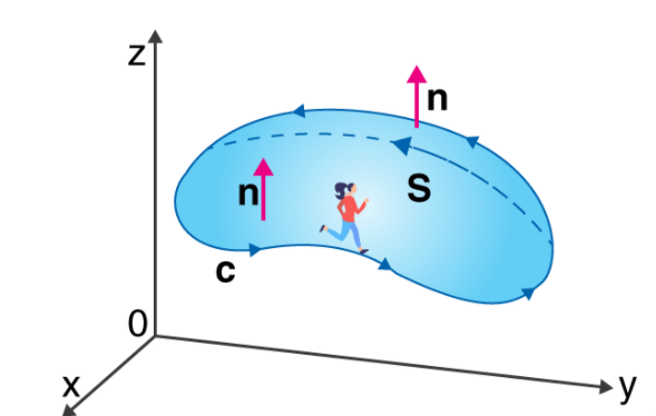
The Stoke’s theorem states that “the surface integral of the curl of a function over a surface bounded by a closed surface is equal to the line integral of the particular vector function around that surface.”
∮CF⃗.dr→=∬S (▽×F⃗ ).dS→
Where,
C = A closed curve.
S = Any surface bounded by C.
F = A vector field whose components have continuous derivatives in an open region of R3 containing S.
This classical declaration, along with the classical divergence theorem, fundamental theorem of calculus, and Green’s theorem are exceptional cases of the general formulation specified above.
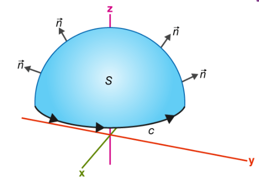
If you walk in the positive direction around C with your head pointing in the direction of n, the surface will always be on your left.
S is an oriented smooth surface bounded by a simple, closed smooth-boundary curve C with positive orientation.
According to Gauss’s theorem the net-outward normal electric flux through any closed surface of any shape is equivalent to 1/ε0 times the total amount of charge contained within that surface
Proof of Gauss’s Theorem Statement:
● Let the charge be = q
● Let us construct the Gaussian sphere of radius = r
Now, Consider, A surface or area ds having ds (vector)
Normal having the flux at ds:
Flux at ds:
d e = E (vector) d s (vector) cos θ
But, θ = 0
Therefore, Total flux:
C = f d Φ
E 4 π r2
Therefore,
σ = 1 / 4πɛo q / r2 × 4π r2
σ = q / ɛo
Gauss’s law for the electric field describes the static electric field generated by a distribution of electric charges. It states that the electric flux through any closed surface is proportional to the total electric charge enclosed by this surface. By convention, a positive electric charge generates a positive electric field. The law was published posthumously in 1867 as part of a collection of work by the famous German mathematician Carl Friedrich Gauss.
Integral Equation
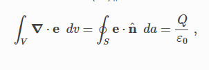
Gauss’s law in integral form is given below:
Where:
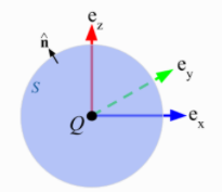
e is the electric field
Q is the enclosed electric charge
ε0 is the electric permittivity of free space
n^ is the outward pointing unit-normal
Flux is a measure of the strength of a field passing through a surface. Electric flux is defined in general as

Gauss’s law tells us that the net electric flux through any closed surface is zero unless the volume bounded by that surface contains a net charge.
Gauss’ Law for Magnetic Fields states that the flux of the magnetic field through a closed surface is zero.
This is expressed mathematically as follows:

Where B is magnetic flux density and S is a closed surface with outward-pointing differential surface normal ds. It may be useful to consider the units. B has units of Wb/m2; therefore, integrating B over a surface gives a quantity with units of Wb, which is magnetic flux, as indicated above.
GLM can also be interpreted in terms of magnetic field lines. For the magnetic flux through a closed surface to be zero, every field line entering the volume enclosed by S must also exit this volume – field lines may not begin or end within the volume. The only way this can be true for every possible surface S is if magnetic field lines always form closed loops.
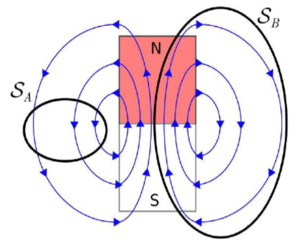
GLM implies there can be no particular particle or structure that can be the source of the magnetic field (because then that would be a start point for field lines). This is one way in which the magnetic field is very different from the electrostatic field, for which every field line begins at a charged particle.
Faraday’s law of electromagnetic induction, also known as Faraday’s law is the basic law of electromagnetism which helps us to predict how a magnetic field would interact with an electric circuit to produce an electromotive force (EMF). This phenomenon is known as electromagnetic induction.
Faraday’s Laws of Electromagnetic Induction
Faraday’s Laws of Electromagnetic Induction consists of two laws. The first law describes the induction of emf in a conductor and the second law quantifies the emf produced in the conductor. In the next few sections, let us learn these laws in detail.
Faraday’s First Law of Electromagnetic Induction
The discovery and understanding of electromagnetic induction are based on a long series of experiments carried out by Faraday and Henry. From the experimental observations, Faraday arrived at a conclusion that an emf is induced in the coil when the magnetic flux across the coil changes with time. With this in mind, Faraday formulated his first law of electromagnetic induction as,
Whenever a conductor is placed in a varying magnetic field, an electromotive force is induced. If the conductor circuit is closed, a current is induced which is called induced current.

Mentioned here are a few ways to change the magnetic field intensity in a closed loop:
● By rotating the coil relative to the magnet.
● By moving the coil into or out of the magnetic field.
● By changing the area of a coil placed in the magnetic field.
● By moving a magnet towards or away from the coil.
Faraday’s Second Law of Electromagnetic Induction
Faraday’s second law of electromagnetic induction states that
The induced emf in a coil is equal to the rate of change of flux linkage.
The flux is the product of the number of turns in the coil and the flux associated with the coil. The formula of Faraday’s law is given below:

Where,
● ε is the electromotive force
● Φ is the magnetic flux
● N is the number of turns
The negative sign indicates that the direction of the induced emf and change in the direction of magnetic fields have opposite signs.
Additionally, there is another key law known as Lenz’s law that describes electromagnetic induction as well.
Faraday’s Law Formula
Consider a magnet approaching towards a coil. Consider two-time instances T1 and T2.
Flux linkage with the coil at the time T1 is given by
T1 = NΦ1
Flux linkage with the coil at the time T2 is given by
T1 = NΦ2
Change in the flux linkage is given by
N (Φ2 – Φ1)
Let us consider this change in flux linkage as
Φ = Φ2 – Φ1
Hence, the change in flux linkage is given by
NΦ
The rate of change of flux linkage is given by
NΦ/t
Taking the derivative of the above equation, we get
N dΦ/dt
According to Faraday’s second law of electromagnetic induction, we know that the induced emf in a coil is equal to the rate of change of flux linkage. Therefore,
E=N dϕ/dt
Considering Lenz’s law,
E=−N dϕ/dt
From the above equation, we can conclude the following
● Increase in the number of turns in the coil increases the induced emf
● Increasing the magnetic field strength increases the induced emf
● Increasing the speed of the relative motion between the coil and the magnet, results in the increased emf
The magnetic field in space around an electric current is proportional to the electric current which serves as its source, just as the electric field in space is proportional to the charge which serves as its source. Ampere's Law states that for any closed loop path, the sum of the length elements times the magnetic field in the direction of the length element is equal to the permeability times the electric current enclosed in the loop.
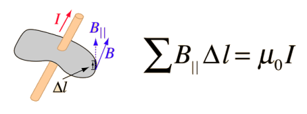
In the electric case, the relation of field to source is quantified in Gauss's Law which is a very powerful tool for calculating electric fields
- Ampere’s law states that “the line integral of resultant magnetic field along a closed plane curve is equal to μ0 time the total current crossing the area bounded by the closed curve provided the electric field inside the loop remains constant".
- Ampere’s law is true only for steady currents.
- Maxwell found the shortcoming in Ampere’s law and he modified Ampere’s law to include time-varying electric fields.
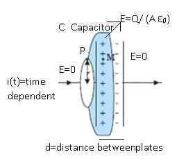
- For Ampere’s circuital law to be correct Maxwell assumed that there has to be some current existing between the plates of the capacitor.
- Outside the capacitor current was due to the flow of electrons.
- There was no conduction of charges between the plates of the capacitor.
- According to Maxwell, between the plates of the capacitor there is an electric field which is directed from the positive plate to the negative plate.
- Magnitude of the electric field E =(V/d)
- Where V=potential difference between the plates, d = distance between the plates.
- E = (Q/Cd)
- Where Q=charge on the plates of the capacitor, Capacitance of the capacitor=C
- =>= (Q/ (Aε0d/d)) where A =area of the capacitor.
- E=Q/(Aε0)
- Direction of the electric field will be perpendicular to the selected surface i.e. if considering plate of the capacitor as surface.
- As E =0 outside the plates and E=(Q/(Aε0)) between the plates.
- There may be some electric field between the plates because of which some current is present between the plates of the capacitor.
- Electric Flux through the surface=ΦE= (EA) =(QA)/ (Aε0) = (Q/ ε0)
- Assuming Q (charge on capacitor i.e. charging or discharging of the capacitor) changes with time current will be generated.
- Therefore, current Id =(dQ/dt)
▪ Where Id =displacement current
- =>Differentiating = (Q/ ε0) on both sides w.r.t time,
- (dΦE/dt) = (1/ ε0) (dQ/dt)
▪ where (dQ/dt) =current
- Therefore (dQ/dt) = ε0 (d ΦE/dt)
- =>Current was generated because of the change of electric flux with time.
- Electric flux arose because of the presence of an electric field in the plates of the capacitor.
- Id = (dQ/dt) = Displacement current
- Therefore, change in the electric field gave rise to Displacement current.
▪ Current won’t be 0 it will be Id.
▪ There is some current between the plates of the capacitor and there is some current at the surface.
▪ At certain points there is no displacement current there is only conduction current and vice-versa.
- Maxwell corrected the Ampere’s circuital law by including displacement current.
- He said that not only the current existed outside the capacitor but also current known as displacement currentexisted between the plates of the capacitor.
- Displacement current exists due to the change in the electric field between the plates of the capacitor.
- Conclusion: - Magnetic fields are produced both by conduction currents and by time varying fields.
Maxwell's equations represent one of the most elegant and concise ways to state the fundamentals of electricity and magnetism. From them one can develop most of the working relationships in the field. Because of their concise statement, they embody a high level of mathematical sophistication and are therefore not generally introduced in an introductory treatment of the subject, except perhaps as summary relationships.
These basic equations of electricity and magnetism can be used as a starting point for advanced courses, but are usually first encountered as unifying equations after the study of electrical and magnetic phenomena.
Integral form in the absence of magnetic or polarizable media:
I. Gauss' law for electricity |  |
II. Gauss' law for magnetism |  |
III. Faraday's law of induction |  |
IV. Ampere's law |  |
Application
By understanding electromagnetism we're able to create images of the body using MRI scanners in hospitals; we've created magnetic tape, generated electricity, and built computers. Any device that uses electricity or magnets is on a fundamental level built upon the original discovery of Maxwell's equations.
While using Maxwell's equations often involves calculus, there are simplified versions of the equations we can study. These versions only work in certain circumstances, but can be useful and save a lot of trouble. Let's look at one of these - the simplified version of Faraday's law.
As a reminder, Faraday's law says that any change to the magnetic environment of a coil of wire will cause a voltage to be induced in the coil. And we can quantify those changes in a simple equation. Doing so gives you this equation below, where N is the number of turns on the coil of wire, delta BA is the change in the magnetic field times the area of the coil of wire, and delta t is the time over which that change occurs.
This equation will give you the voltage produced in the coil. If anything changes the values of B or A, a voltage will be produced.
Magnetic permeability is defined as the ratio of the magnetic induction to the magnetic intensity. It is a scalar quantity and denoted by the symbol μ. Magnetic permeability helps us measure a material’s resistance to the magnetic field or measure of the degree to which the magnetic field can penetrate through a material.
If the material has greater magnetic permeability, greater will be the conductivity for magnetic lines of force.
Factors Affecting Magnetic Permeability
Permeability also depends on several factors such as the nature of the material, humidity, position in the medium, temperature, and frequency of the applied force. Magnetic permeability is always positive and can vary with a magnetic field. Meanwhile, the opposite of magnetic permeability is magnetic reluctivity.
Magnetic Permeability Formula
Magnetic permeability formula is given as;
Magnetic permeability (u) = B/H
Where B = magnetic intensity and H = magnetising field.
The SI unit of magnetic permeability is henries per meter (H/m) or newtons per ampere squared (N⋅A−2).
Types of Permeability
The different types of permeability include;
Permeability of Free Space
Also known as the permeability of free space, air or vacuum.
It is represented by u0=B0/H
The ratio of magnetic intensity in a vacuum and magnetising field.
Permeability of Medium
The ratio of magnetic intensity in the medium and magnetising field.
It is expressed as;
u = B/H
The magnetization of a given sample material M can be defined as the net magnetic moment for that material per unit volume.
Mathematically,

Let us now consider the case of a solenoid. Let us take a solenoid with n turns per unit length and the current passing through it be given by I, then the magnetic field in the interior of the solenoid can be given as,

Now, if we fill the interior with the solenoid with a material of non-zero magnetization, the field inside the solenoid must be greater than before. The net magnetic field B inside the solenoid can be given as,

Where Bm gives the field contributed by the core material. Here, Bm is proportional to the magnetization of the material, M. Mathematically,

Here, µ0 is the constant of permeability of a vacuum.
The magnetic intensity of a material can be given as,

From this equation, we see that the total magnetic field can also be defined as,

Here, the magnetic field due to the external factors such as the current in the solenoid is given as H and that due to the nature of the core is given by M. The latter quantity, that is M is dependent on external influences and is given by,

Where χ is the magnetic susceptibility of the material. It gives the measure of the response of a material to an external field. The magnetic susceptibility of a material is small and positive for paramagnetic materials and is small and negative for diamagnetic materials.

A current loop has a magnetic moment μ, so for the orbiting electron we get:
μ = IA = (ev/2πr) * (πr2) = evr/2
If we multiply top and bottom by m, the electron mass, we get mvr in the numerator. This is the orbital angular momentum of the electron, L.
Therefore, by the Bohr model, μ = eL/2m. The orbital magnetic moment of the electron is proportional to its orbital angular momentum. The orbital angular momentum is quantized in multiples of h_bar = h/2π, where h is Planck's constant. The Bohr model is rather simplistic; an analysis using quantum mechanics shows that the smallest non-zero value of the electron's orbital magnetic moment is:
μ = (2)1/2 e h_bar /2m
Another contribution to an atom's magnetic moment comes from electron spin. The magnetic moment associated with electron spin is:
μspin = e h_bar/2m
This combination of factors is known as the Bohr magneton:
μB = e h_bar/2m = 9.27 x 10⁻²⁷ J/T
The net magnetic moment of an atom is the vector sum of its orbital and spin magnetic moments. Many materials are not magnetic (i.e., they don't act like bar magnets) because the magnetic moments completely or mostly cancel. In materials you can make bar magnets out of, however, neighboring atoms interact in such a way that their magnetic moments are aligned. In other words, the material acts like one big current loop, producing a magnetic field.
The magnetic materials are generally classified into three types based on the behaviour of materials in a magnetising field. They are diamagnetic, paramagnetic and ferromagnetic materials which are dealt with in this section.
a) Diamagnetic materials
The orbital motion of electrons around the nucleus produces a magnetic field perpendicular to the plane of the orbit. Thus, each electron in orbit has a finite orbital magnetic dipole moment. Since the orbital planes are oriented in a random manner, the vector sum of magnetic moments is zero and there is no resultant magnetic moment for each atom.
In the presence of an external magnetic field, some electrons are speeded up and some are slowed down. The electrons whose moments were anti-parallel are speeded up according to Lenz’s law and this produces an induced magnetic moment in a direction opposite to the field. The induced moment disappears as soon as the external field is removed.
When placed in a non-uniform magnetic field, the interaction between induced magnetic moment and the external field creates a force which tends to move the material from stronger part to weaker part of the external field. It means that diamagnetic material is repelled by the field.
This action is called diamagnetic action and such materials are known as diamagnetic materials. Examples: Bismuth, Copper and Water etc.
The properties of diamagnetic materials are
i. Magnetic susceptibility is negative.
Ii. Relative permeability is slightly less than unity.
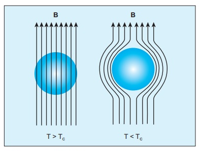
Iii. The magnetic field lines are repelled or expelled by diamagnetic materials when placed in a magnetic field.
Iv. Susceptibility is nearly temperature independent.
(b) Paramagnetic materials
In some magnetic materials, each atom or molecule has a net magnetic dipole moment which is the vector sum of orbital and spin magnetic moments of electrons. Due to the random orientation of these magnetic moments, the net magnetic moment of the materials is zero.
In the presence of an external magnetic field, the torque acting on the atomic dipoles will align them in the field direction. As a result, there is a net magnetic dipole moment induced in the direction of the applied field. The induced dipole moment is present as long as the external field exists.
When placed in a non-uniform magnetic field, the paramagnetic materials will have a tendency to move from weaker to stronger part of the field. Materials which exhibit weak magnetism in the direction of the applied field are known as paramagnetic materials. Examples: Aluminium, Platinum and chromium etc.
The properties of paramagnetic materials are:
I. Magnetic susceptibility is positive and small.
II relative permeability is greater than unity.
Iii. The magnetic field lines are attracted into the paramagnetic materials when placed in a magnetic field.
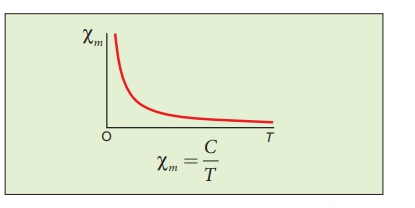
Iv. Susceptibility is inversely proportional to temperature.
Curie’s law
When temperature is increased, thermal vibration will upset the alignment of magnetic dipole moments. Therefore, the magnetic susceptibility decreases with increase in temperature. In many cases, the susceptibility of the materials is

This relation is called Curie’s law. Here C is called Curie constant and temperature T is in kelvin. The graph drawn between magnetic susceptibility and temperature is shown in Figure 3.26, which is a rectangular hyperbola.
(c)Ferromagnetic materials
An atom or a molecule in a ferromagnetic material possesses net magnetic dipole moment as in a paramagnetic material. A ferromagnetic material is made up of smaller regions, called ferromagnetic domain. Within each domain, the magnetic moments are spontaneously aligned in a direction. This alignment is caused by strong interaction arising from electron spin which depends on the inter-atomic distance. Each domain has net magnetisation in a direction. However, the direction of magnetisation varies from domain to domain and thus net magnetisation of the specimen is zero.
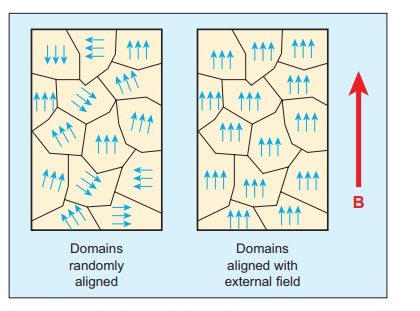
In the presence of external magnetic field, two processes take place
1. the domains having magnetic moments parallel to the field grow in size
2. the other domains (not parallel to field) are rotated so that they are aligned with the field.
Antiferromagnetic
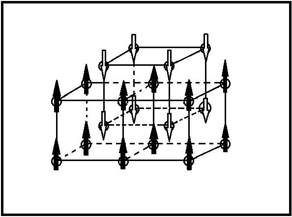
Antiferromagnets are like ferromagnets but their magnetic moments align antiparallel to the neighboring moments. This alignment occurs spontaneously below a critical temperature known as the Neel temperature.
Antiferromagnetic materials spontaneously align their magnetic moments antiparallel when a magnetic field is applied and at temperatures below the critical temperature. The magnetization of an antiferromagnet remains constant below that critical temperature and the material retains this antiparallel alignment when the external field is removed. The magnetic moments come from the spin of the atomic valence electrons. Without a magnetic field applied to the material, the magnetic moments of each orbiting electron are all randomly oriented. When a magnetic field is applied to the material, the magnetic moments of the electrons respond and align antiparallel to each neighboring moment
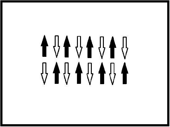
This creates two opposing magnetic moment sublattices and thus a total magnetic moment of zero.
Ferrimagnetic
Unlike ferromagnetic materials, which are typically metals, ferrimagnetic materials are ceramics, in particular, ceramic oxides. The most widely used ferrimagnets in technological devices are materials known as ferrites. Ferrites are electrically insulating transitional-metal oxides with the general chemical formula MO·Fe2·O3, where M is a divalent ion such as Mn2+, Fe2+, Co2+, or Ni2+.
Ferrites are often prepared by standard ceramic processing techniques. In the case of NiO.Fe2·O3 powders of NiO and Fe2O3 are mixed together and pressed into the desired shape before sintering (firing) at high temperature to form a dense ceramic of the desired composition. This method provides a reliable way of forming a wide variety of shapes and sizes of ferrimagnetic materials for embedding into technological devices.
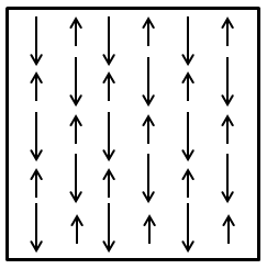
The hysteresis loop shows the relationship between the intensity of magnetization and the magnetizing field. The loop is generated by measuring the magnetic flux coming out from the ferromagnetic substance while changing the external magnetizing field.
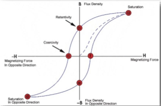
Looking at the graph, if B is measured for various values of H and if the results are plotted in graphic forms then the graph will show a hysteresis loop.
● The intensity of the magnetism (B) is increased when the magnetic field (H) is increased from 0 (zero).
● With increasing the magnetic field there is an increase in the value of magnetism and finally reaches point A which is called saturation point where B is constant.
● With a decrease in the value of the magnetic field, there is a decrease in the value of magnetism. But if B and H are equal to zero, substance or material retains some amount of magnetism called retentivity or residual magnetism.
● When there is a decrease in the magnetic field towards the negative side, magnetism also decreases. At point C the substance is completely demagnetized.
● The force required to remove the retentivity of the material is known as Coercive force (C).
● In the opposite direction, the cycle is continued where the saturation point is D, retentivity point is E and coercive force is F.
● Due to the forward and opposite direction process, the cycle is complete and this cycle is called the hysteresis loop.
Advantages of Hysteresis Loop
1. A smaller region of loop hysteresis is indicative of less loss of hysteresis.
2. Hysteresis loop provides a substance with the importance of retentivity and coercivity. Therefore, the way to select the right material to make a permanent magnet is made simpler by the heart of machines.
3. Residual magnetism can be calculated from the B-H graph and it is, therefore, simple to choose material for electromagnets.
Application:
The significance of the hysteresis loop is that it provides information such as retentivity, coercivity, permeability, susceptibility and energy loss during one cycle of magnetisation for each ferromagnetic material. Therefore, the study of hysteresis loop will help us in selecting proper and suitable material for a given purpose. Some examples:
i) Permanent magnets:
The materials with high retentivity, high coercivity and high permeability are suitable for making permanent magnets. Examples: Steel and Alnico
Ii) Electromagnets:
The materials with high initial permeability, low retentivity, low coercivity and thin hysteresis loop with smaller area are preferred to make electromagnets.
Examples: Soft iron and Mumetal (Nickel Iron alloy).
Iii) Core of the transformer:
The materials with high initial permeability, large magnetic induction and thin hysteresis loop with smaller area are needed to design transformer cores.
Examples: Soft iron