UNIT 2
Coherent waves and Optics in Communication
Interference in Parallel Film (Reflected Rays)
Consider a thin film of uniform thickness ‘t’ and refractive index  bounded between air. Let us consider monochromatic ray AB is made incident on the film, at B part of ray is reflected (R1) and a part is refracted along BC. At C The beam BC again suffers partial reflection and partial refraction, the reflected beam CD moves again suffer partial reflection and partial refraction at D. The refracted beam R2 moves in air. These two reflected rays R1 and R2 interfere to produce interference patterns.
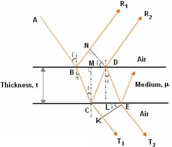
The optical path difference between the two reflected rays

In ΔBDN, sin i = BN / BD and BC = CD as ΔBMC ≡ ΔMCD, therefore

In ΔBMC, cos r = t /BC, therefore


In ΔBMC, tan r = BM / t , therefore

According to Snell’s law 


Correction on account of phase change at reflection:
When a beam is reflected from a denser medium (ray R1 at B), a path change of  /2 occurs for the ray.
Therefore, the true path difference is 
Condition of Maxima (Bright Fringe)
Maxima occur when path difference


 ..
..
Condition for Minima (Dark Fringe)
Minima occur when path difference


Interference in Parallel Film (Transmitted Rays)
The optical path difference between transmitted rays T1 and T2 will be
This path difference is calculated in the same way as above to get
 .
.
Condition of Maxima (Bright Fringe)
Maxima occur when path difference,

 .....
.....
Condition for Minima (Dark Fringe)
Minima occur when path difference,


NEWTON'S RINGS are the circular interference patterns first discovered by Newton.
Formation of fringes
When a plano-convex lens with large radius of curvature is placed on a plane glass plate such that its curved surface faces the glass plate, a wedge air film (of gradually increasing thickness) is formed between the lens and the glass plate. The thickness of the air film is zero at the point of contact and gradually increases away from the point of contact.
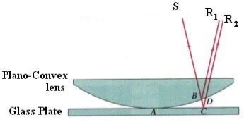
If monochromatic light is allowed to fall normally on the lens from a source 'S', then two reflected rays R1 (reflected from upper surface of the film) and R2 (reflected from lower surface of the air film) interfere to produce circular interference pattern. This interference pattern has concentric alternate bright and dark rings around the point of contact.
Theory of Fringes:
The effective path difference between the two reflected rays R1 and R2 for a wedge-shaped film

If the light is incident normally on the lens, r = 0 and near to point of contact  is small; there-fore near point of contact,
Therefore 
At point of contact t = 0 therefore the effective path difference is Δ = λ/2 which is an odd multiple of λ/2 There-fore the Central fringe is dark.
Condition of Maxima (Bright Fringe): The effective path difference  ; substituting this


Condition for Minima (Dark Fringe): The effective path difference ; substituting this in equation

 …
…
From above it is clear that for particular dark or bright fringe t should be constant.
Every fringe is the locus of points having equal thickness. Hence the fringes are circular in shape.
Diameter of Newton’s Rings:
To calculate the diameter of fringes, assume a plano-convex lens is placed on a plane glass plate as shown in figure say R be the radius of curvature of lens. In ΔO’ML
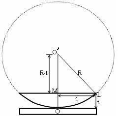


As t << R; neglecting t2 (small value)


Diameter of Dark Rings
Substitute this


As Dn = 2rn


The medium enclosed between the lens and glass plate is if air therefore,  = 1. The diameter of nth order dark fringe will be
 ….
….
 ; n = 0, 1, 2, 3, 4….
The diameter of dark ring is proportional to square root of natural numbers
Diameter of Bright Rings
Substitute t above:


As Dn = 2rn


The medium enclosed between the lens and glass plate is if air therefore, = 1. The diameter of nth order bright fringe will be
 …..
…..
 ; n = 0, 1, 2, 3, 4….
The diameter of bright ring is proportional to square root of odd natural numbers
Spacing between Fringes
The Newton’s rings are not equally spaced because the diameter of ring does not increase in the same proportion as the order of ring and rings get closer and closer as ‘n’ increases.
For example, the diameter of dark ring is given by
Where n = 0, 1, 2, 3, 4….


From above, we conclude that the fringe width reduces with increase in ‘n’.
Newton’s Ring with White Light
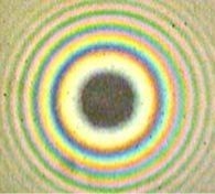
If the monochromatic source is replaced by the white light few coloured rings are seen around dark centre later illumination is seen in the field of view.
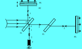
In the Michelson interferometer the two coherent sources are derived from the principle of division of amplitude. The parallel light rays from a monochromatic source are incident on beams splitter (glass plate) G1 which is semi silvered on its back surface and mounted at 45° to the axis. Light ray incident ‘O' is refracted into the glass plate and reaches point A , where it is partially reflected (ray 1) and partially transmitted ray 2. These rays then fall normally on mirrors M1 (movable) and M2 (fixed) and are reflected back. These reflected rays reunite at point A again and follow the path AT. Since these two rays are derived from the same source (at A) and are therefore coherent, they can interfere and form interference patterns.
In this geometry, the reflected ray 1, travels an extra optical path, a compensating plate G2 of same thickness as plate G1) is inserted in the path of ray 2 such that G2 is parallel to G1. This introduces the same optical path in glass medium for ray 2 as ray 1 travels in plate G1 (therefore is called a compensating plate). Any optical path difference between the ray 1 and ray 2 is now equal to the actual path difference between them.
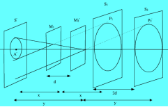
To understand how the fringes are formed, refer to fig. An observer at 'T' will see the images of mirror M2 and source S ( M'2 and S' respectively) through beam splitter along with the mirror M1. S1 and S2 are the images of source in mirrors M1 and M2 respectively. The position of these elements in figure depend upon their relative distances from point A .
Formation of fringes:
If ‘d ' is the separation between mirrors M1 and M2' then ‘2d' is the separation between virtual sources S1 and S2 the path difference between the two parallel rays coming from point P1 and P2 respectively and reaching the eyepiece is equal to  .
.
 (bright)
 (dark)
These fringes are concentric rings or straight lines depending upon the mutual inclination of mirrors M1 and M2(M2’). If mirrors M1 and M2 are parallel to each other the case similar to the air film between two parallel plates and fringes formed are concentric rings.
Michelson interferometer is used to determine the wavelength of a monochromatic source, the difference between two wavelengths, determination of thickness/refractive index of thin transparent sheet.
Determination of wavelength ( )
)
(A) If the mirror M2 is not exactly perpendicular to mirror M1 (in this case mirror M1 and image M'2 of mirror M2 will not be exactly parallel), a wedge shaped air film is formed between M1 and M'2. The two reflected waves from M1 and M2 are no longer parallel but appear to diverge from some point near M1 (see fig) and are localised fringes.
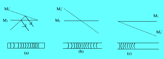
These localized fringes are equidistant straight lines, parallel to the edge of the wedge provided ‘d' is small so that variation in path difference is practically due to variation in film thickness only. If d is increased, the fringes will not be exactly straight due to some variation of path difference with the angle between M1 and M'2. In this case fringes
Become convex towards the edge of the wedge. If the separation between M1 and M'2 is decreased the fringes move across the field towards the thick part of wedge. As d is changed by  , a new fringe crosses the center. At this time, fringes gradually become straightened.
Now if we change the position of the movable mirror M2, then the path difference is changed. When the distance between the mirror is changed by  , the next order bright ring appears at the center. Thus, by recording the position of movable mirror and the number N of central bright rings moved, can determine
  using the following relation.

Where x is the difference between the position of movable mirror during which ‘n' new bright ring appear at the center.
Determination of difference in wavelength:
When the light coming from the source consists of two closely spaced wavelength (such as D1 and D2 lines of sodium vapour lamp  ) each wavelength produces its own fringe pattern. When the separation between M1 and M'2 is small. The rings due to
  and
and  almost coincides.
When separation ‘d' between the mirrors M1 and M'2 is increased the two rings patterns have different spacing (fringe width due to two are different) and rings of  is gradually separated by those due to
  . At certain spacing ‘ d ' between mirrors, the dark ring of
  coincides with bright rings of
  and the rings have maximum indistinctness.
As the mirror M1 is moved further away (d increases) the rings due to  and
and  become most distinct and indistinct periodically. Let x is the distinct by which the mirror M1 is moved for two consecutive situations when ring due to
  and
and  are maximum indistinct. During the movement, n fringes of
  and
and  fringes of
  have appeared at the center (only then dark ring of
  will again coincide with bright ring of
  ). Since each time mirror M1 is moved by
  , a new ring appear at the center hence,

or,  and
and


Since  and
and  are close together,
  product can be replaced by
  Thus, we have

Knowing  and x, we can determine the difference in wavelength of two very close wavelengths using Michelson infer meter.
Fraunhofer Diffraction : In the case of Fraunhofer diffraction, both the source and slit are very far from the diffracting aperture. In other words, this is equivalent to saying that the light originating from the source (where it has a spherical wavefront) when reaches at the aperture, the wavefront is nearly plane. The intensity of light at each point of aperture is thus nearly same. (If the distance between source and slit is not large, the wavefront at the aperture will be spherical and intensity of light at each point of aperture will be different).
After diffraction, each point of wavefront at aperture, will act as a new source of light and will spread as spherical wavefront .When the screen is very far from the aperture, the wavefront reaching the screen will again be planar and the wavefronts converging on any point on the screen will have same amplitude, and thus we need not worry about difference in field strength from different wavefronts.
Diffraction by a narrow single slit
Consider a single slit (a rectangular aperture, whose length is larger compared to its breadth, and breadth is quite narrow, comparable to the wavelength of light  0.1 mm for visible light) placed in front of a monochromatic light source
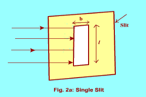
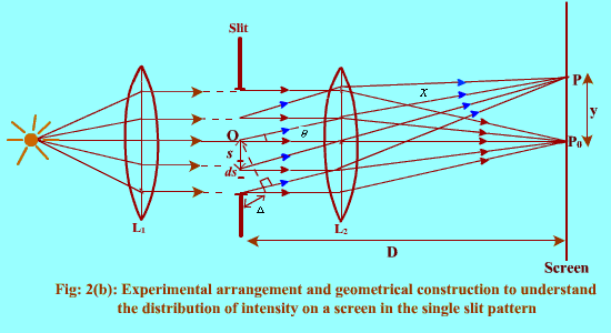
When a plane wave front is incident on the slit, each point on the wave front acts as the source of spherical secondary wave fronts. Divide the wave front incident on the slit in a large number of elements, each of width ds, (infinitesimally small).
The part of each secondary wave, originating from these small elements and travelling normal to the plane of slit will be focussed at P0 while those travelling at an angle  will reach P. Considering first the wavelet emitted by the element ds situated at the center of slit (let us call it origin). Its amplitude will be directly proportional to length ds and inversely proportional to the distance x (it will produce spherical wave front). At P, it will produce an infinitesimal amplitude (electric field) which is expressed as

Where 'a' is the amplitude of incident wave,  and
and  are its frequency and wave vector respectively.
The wave fronts reaching P from other elements ds will vary in phase due to extra path travelled by them. The displacements produced by another element ds at a distance s from the center(origin) will be given by


Where  Is the path different?
The net amplitude at P will be sum of effect due to all the elements ds and can be obtained by integrating dEs from s=-d/2 to d/2 where d is the width of the slit. In doing so, we can first sum the amplitude produced by the symmetrically placed elements ds and then integrate it from s=0 to d/2. The contribution due to a pair of symmetrically placed element ds is


Using the trigonomerical identity  We have

Net effect at P is now

We can treat  constant,
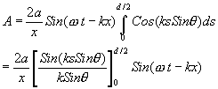

Where 
The resultant wave reaching at P, is therefore a simple harmonic one. The amplitude of this varies as position P is varied ( varies). The resultant amplitude is given by

Where 
The intensity of light at any point on screen is, thus given by

Rayleigh Criterion of Resolution
Statement:
Two sources are resolvable by an optical instrument when the central maximum of one diffraction pattern falls over the first minimum of the other diffraction pattern and vice versa.
For example:
Let us consider the resolution of two wavelengths and by a grating. When the difference in wavelengths is smaller and such that the central maximum of the wavelength coincides with the first minimum of the other as shown in figure, then the resultant intensity curve is as shown by the thick curve. The curve shows a distinct dip in the middle of two central maxima. Thus, the two wavelengths can be distinguished from one another and according to Rayleigh they are said to be “Just Resolved”.
If the difference in wavelengths is such that their principal maxima are separately visible, then there is a distinct point of zero intensity in between the two wavelengths. Hence according to Rayleigh, they are said to be “Resolved”.
When the difference in wavelengths is so small that the central maxima corresponding to two wavelengths come still closer as shown in figure, then the resultant intensity curve is quite smooth without any dip. This curve is as if there is only one wavelength somewhat bigger and stronger.
Hence according to Rayleigh, the two wavelengths are “Not Resolved”.
Thus, the two spectral lines can be resolved only up to a certain limit expressed by Rayleigh Criterion.

Resolving Power of Grating
It is defined as the capacity of a grating to form separate diffraction maxima of two wavelengths which are very close to each other
It is measured by  where
where  is the smallest difference in two wavelengths which are just resolvable by grating and
 is the wavelength of either of them or mean wavelength.
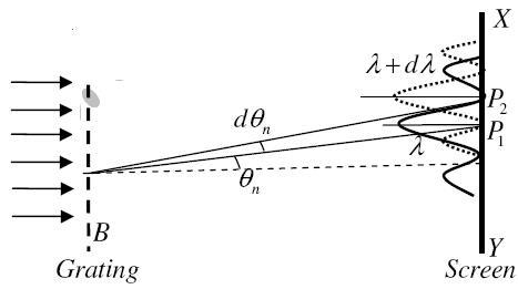
Let AB represent the surface of a plane transmission grating having grating element (e+d) and N total number of slits. Let a beam of light having two wavelengths  and
and  is normally incident on the grating. Let P1 is nth primary maximum of a spectral line of wavelength
  at an angle of diffraction
  and P2 is the nth primary maximum of wavelength
  at diffracting angle
According to Rayleigh criterion, the two wavelengths will be resolved if the principal maximum  of nth order in a direction
  falls over the first minimum of nth order in the same direction
  . Let us consider the first minimum of l of nth order in the direction
  as below.
The principal maximum of  in the
  direction is given by
 ...
...
The equation of minima is  where m takes all integers except 0, N, 2N, …, nN, because for these values of m, the condition for maxima is satisfied. Thus, first minimum adjacent to nth principal maximum in the direction
 can be obtained by substituting the value of ‘m’ as (nN+1). Therefore, the first minimum in the direction of
  is given by

 ..
..
The principal maximum of  in direction
  is given by
 ..
..
Dividing eqns, we get


 .
.
Thus, the resolving power is directly proportional to
(i) The order of the spectrum ‘n’
(ii) The total number of lines on the grating ‘N’
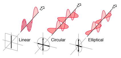
Light in the form of a plane wave in space is said to be linearly polarized. Light is a transverse electromagnetic wave, but natural light is generally unpolarized, all planes of propagation being equally probable. If light is composed of two plane waves of equal amplitude by differing in phase by 90°, then the light is said to be circularly polarized. If two plane waves of differing amplitude are related in phase by 90°, or if the relative phase is other than 90° then the light is said to be elliptically polarized
. 
Difference between Reflection and Refraction | |
Reflection | Refraction |
This phenomenon usually occurs in mirrors. | This phenomenon usually occurs in Lenses. |
Reflection can simply be defined as the reflection of light when it strikes the medium on a plane. | Refraction can be defined as the process of the shift of light when it passes through a medium leading to the bending of light. |
The light entering the medium returns to the same direction. | The light entering the medium travels from one medium to another. |
Considering the light waves, they bounce from the plane and change direction. | The light waves pass through the surface while simultaneously changing from medium to medium. |
The angle of incidence of the light is equal to the angle of reflection. | The angle of incidence is not equal to the angle of reflection. |
When unpolarized light of a certain wavelength is incident upon the surface of a transparent substance it experiences maximum plane polarization at the angle of incidence whose tangent is the refractive index of the substance.
The specific value of angle of incidence at which the reflected light is completely polarized is called the polarizing angle

Where,
● µ is the refractive index of the medium
● ip is the polarizing angle
Brewster’s law states that, the tangent of polarising angle of incidence to the transparent medium is equal to the refractive index of the medium
Tan ip=mu
Ip- polarising angle of incidence
Ip= tan–1 μ
The angle is depending on the refractive index of the medium.
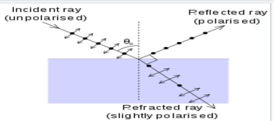
Malus’ law states that the intensity of plane-polarized light that passes through an analyser varies as the square of the cosine of the angle between the plane of the polarizer and the transmission axes of the analyser.
Understand the expression for Malus’ law.
Point 1 – When Unpolarized light is incident on an ideal polarizer the intensity of the transmitted light is exactly half that of the incident unpolarized light no matter how the polarizing axis is oriented.
Point 2 – An ideal polarizing filter passes 100% of incident unpolarized light, that is polarized in the direction of the filter's (Polarizer) Polarizing axis.
From point (1) and point (2) we can assume I = Io cos2 ϕ
The average value of I (< I >):
We know


Which satisfies point (2) mentioned above.
To show point (1), let us consider ϕ = 0
That implies cos2ϕ = 1
I = I0
To determine the direction of polarization we need one polarizer which is known as analyser oriented making an angle (p) with the polarizer.
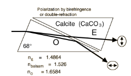
Double refraction, also called birefringence, an optical property in which a single ray of unpolarized light entering an anisotropic medium is split into two rays, each traveling in a different direction. One ray (called the extraordinary ray) is bent, or refracted, at an angle as it travels through the medium; the other ray (called the ordinary ray) passes through the medium unchanged.
A birefringent substance will split unpolarized light into two polarized rays with different refractive indices and different velocities. A crystal of calcite demonstrates this phenomenon.
The optic axis of a crystal is defined by the symmetry of the lattice. In calcite CaCO3, the CO3 forms a triangular cluster, and the optic axis is perpendicular to this. If light enters along the optic axis, nothing dramatic happens and the light emerges unpolarized.
If however the light enters at an angle to this axis, the asymmetry of the lattice splits the ray into two with mutually perpendicular polarizations. One ray is called the Ordinary ray, for which Snell's law holds. The other Extraordinary ray does not obey Snell's law.
Birefringence in a calcite crystal
Observing an object through the crystal, one sees a double image. Analysis through a Polaroid sheet shows that these images have axes of polarization at right angles to each other; rotating the Polaroid makes the images alternately vanish. Things get really exciting when you place a second crystal on top of the first. Now you have four images, but if you rotate it, it acts as an analyser for the first crystal, and you can go down to two images again.
Nicol Prism: This is the most simple and elegant polarizer and analyser. It is an optical device made from a calcite crystal, based on the principle of double refraction, and used to produce and analyse the PPL. In double refraction the incident light split into two components. One is ordinary, obeys all laws of refraction and move with the same velocity in all direction inside crystal known as ordinary ray.
The other one is extraordinary ray does not obey law of refraction and its velocity changes with direction inside the crystal.
In Nicol prism, O-ray is eliminated using optical means by 'Total internal reflection' and the transmitted ray is E-ray in which the vibration of electric field is in single direction i.e. light is PPL.
Construction: Nicol prism is constructed from a calcite crystal whose length is nearly three times its width. The end faces of the crystal out down so as to reduce the angles in the principal section to a more acute angle of 68° instant of 71°. The crystal is then cut along the diagonal and the two cut surfaces after grinding and polishing, cemented back together with a special cement called Canada balsam which is a transparent substance.
Working: When light from source S is incident on surface PQ, at point M it divides into two refracted rays due to double refraction, one is ordinary and other is extraordinary.
The Nicol prism is constructed in such a way that O-ray strikes the Canada balsam layer at critical angle (69°) or more than this value. Since for the calcite µo = 1.468 and for Canada balsam µeb = 1.55, then the light travels from a denser to a rarer medium and incidence angle is equal or more than the critical angle hence the light gets totally reflected. Hence, the O-ray suffers TIR at the Canada balsam layer. It then travels towards the blackened surface where it is absorbed.

TIR
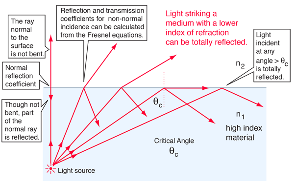
When light is incident upon a medium of lesser index of refraction, the ray is bent away from the normal, so the exit angle is greater than the incident angle. Such reflection is commonly called "internal reflection". The exit angle will then approach 90° for some critical incident angle θc, and for incident angles greater than the critical angle there will be total internal reflection.
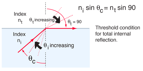
The critical angle can be calculated from Snell's law by setting the refraction angle equal to 90°. Total internal reflection is important in fiber optics and is employed in polarizing prisms.
A laser is a coherent and focused beam of photons; coherent, in this context, means that it is all one wavelength, unlike ordinary light which showers on us in many wavelengths.
The acronym laser stands for "light amplification by stimulated emission of radiation." Lasers work as a result of resonant effects. The output of a laser is a coherent electromagnetic field. In a coherent beam of electromagnetic energy, all the waves have the same frequency and phase.
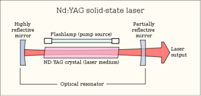
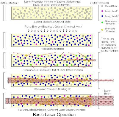
In a basic laser, a chamber called a cavity is designed to internally reflect infrared (IR), visible-light, or ultraviolet (UV) waves so they reinforce each other. The cavity can contain gases, liquids, or solids. The choice of cavity material determines the wavelength of the output. At each end of the cavity, there is a mirror. One mirror is totally reflective, allowing none of the energy to pass through; the other mirror is partially reflective, allowing approximately 5 percent of the energy to pass through. Energy is introduced into the cavity from an external source; this is called pumping.
As a result of pumping, an electromagnetic field appears inside the laser cavity at the natural (resonant) frequency of the atoms of the material that fills the cavity. The waves reflect back and forth between the mirrors. The length of the cavity is such that the reflected and re-reflected wave fronts reinforce each other in phase at the natural frequency of the cavity substance. Electromagnetic waves at this resonant frequency emerge from the end of the cavity having the partially-reflective mirror. The output may appear as a continuous beam, or as a series of brief, intense pulses.
Coherence:
The light from a laser is said to be coherent, which means that the wavelengths of the laser light are in phase in space and time. Large number of identical
photons are emitted through stimulated emission and therefore they will be in phase with each other.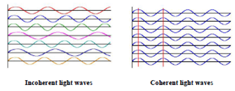
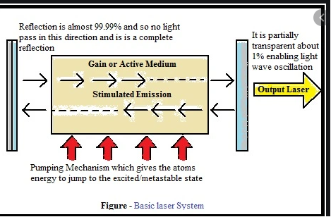
A simple laser consists of a chamber identified as the cavity that is built to reflect waves of visible, infrared or ultraviolet to reinforce one another. The cavity may either include liquids, solids or gases. The material selection in the cavity decides the output wavelength. Mirrors are located at either end of the cavity. One of the mirrors is fully reflective so that none of the light will pass into them. The other mirror is reflective in part, allowing 5 percent of the light to pass through it. Energy is pumped into the cavity from an external source through a method known as pumping.
The waves in between the mirrors are reflected back and forth. The length of the cavity is such that waves that are reflected reinforce each other. At the end of the cavity, with a partially reflective mirror, the electromagnetic waves emerge in harmony with one another. The laser output is a coherent, electric field. Both waves have the same phase and frequency in a coherent beam of electromagnetic energy.
Population inversion
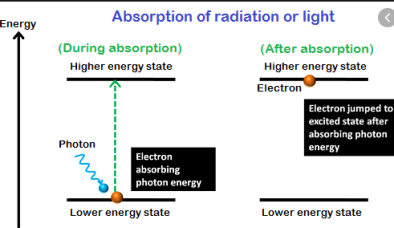
Under normal circumstances, the higher an energy level is, the less it is populated by thermal energy. Under some circumstances (for example, the presence of an upper energy level that has a relatively long lifetime), a system can be constructed so that there are more atoms/molecules in an upper energy level than is allowed under conditions of normal thermodynamic equilibrium. Such an arrangement is called a population inversion.
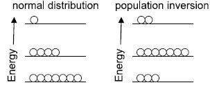
When a population inversion exists, an upper-state system will eventually give off a photon of the proper wavelength and drop to the ground state. This photon, however, can stimulate the production of other photons of exactly the same wavelength because of stimulated emission of radiation. Thus, many photons of the same wavelength (and phase, and other similar characteristics) can be generated in a short time. This is light amplification by stimulated emission of radiation, or LASER—usually seen in lowercase as a laser. Lasers typically have a very narrow wavelength range of emission.
Many types of energy levels—electronic, vibrational, bands in semiconductors—are used to make lasers. Many materials are active laser sources, including Cr3+ ions in ruby and alexandrite crystals, Ti3+ in sapphire, Nd3+ in garnet, and a variety of doped semiconductors. Gases or gas mixtures like He/Ne, Ar, Kr, CO2, N2, even Cu(g) can be made to lase. Certain organic dyes can also be made to lase; one advantage is that their laser action has a broader range of wavelengths (20-30 nm) and they can be tuned to a particular wavelength.
Some imp. Points--
1. Energy is applied to active medium raising active centres to excited energy levels.
2. These atoms spontaneously decay to a relatively long-lived, lower energy, metastable state
3. A population inversion is achieved when the majority of atoms have reached this metastable state
4. Lasing action occurs when an electron spontaneously returns to its ground state and produces a photon.
5. If the energy from this photon is of the precise wavelength, it will stimulate the production of another photon of the
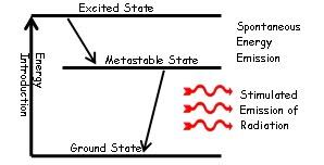
Same wavelength and resulting in a cascading effect.
6. The highly reflective mirror and partially reflective mirror continue the reaction by directing photons back through the medium along the long axis of the laser.
7. The partially reflective mirror allows the transmission of a small amount of coherent radiation that we observe as the “beam”.
8. Laser radiation will continue as long as energy is applied to the lasing medium.
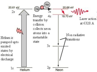
The most common and inexpensive gas laser, the helium-neon laser is usually constructed to operate in the red at 6328 Å. It can also be constructed to produce laser action in the green at 5435 Å and in the infrared at 15,230 Å.
The He – Ne laser has following main parts:

1. The working substance (active medium)- is a long gas discharge tube filled with Helium and Neon gases in ratio 10:1. Ne atoms are active centres where He atoms helps Ne in achieving population inversion.
2. The resonance cavity- the two mirrors arranged externally one is fully reflective and other is partially transmissive forms the optical resonator.
3. Pumping scheme- atoms are excited by electrical discharge. The He atom is pumped to an excited state by electrical discharge. One of the excited levels of helium at 20.61 eV is very close to a level in neon at 20.66 eV, so close in fact that upon collision of helium and a neon atom, the energy can be transferred from the helium to the neon atom during collision. Thus, the population inversion is achieved between E4 and E3 of Neon atom.
Ruby laser:
The ruby laser is the first type of laser actually constructed, first demonstrated in 1960 by T. H. Maiman. The ruby mineral (corundum) is aluminium oxide (Al2O3 ) with a small amount (about 0.05%) of chromium ions (Cr3+) which gives it its characteristic pink or red color by absorbing green and blue light.
The ruby laser is used as a pulsed laser, producing red light at 6943Å. After receiving a pumping flash from the flash tube, the laser light emerges for as long as the excited atoms persist in the ruby rod, which is typically about a millisecond.
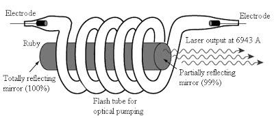
The ruby laser has following main parts:
1. The working substance (active medium)- is in the form of a rod of ruby crystal (10 cm in length, 0.8 cm in diameter) in which Cr3+ are active centres while Al and O2 are inert.
2. The resonance cavity- is made by silvering and polishing the ends of ruby rods. Fully reflecting plates at the left and a partially reflecting plate at the right, both optically plane and accurately parallel.
3. The optical pumping system consists of a helical xenon discharge tube. It produces a flash of a few milliseconds.
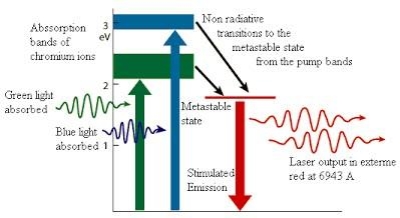
Ruby laser uses a three-level pumping scheme. The xenon discharge generates a flash of white light for a few milliseconds. The Cr+3 ions are excited to the E3 level by absorbing green and blue components of white light. From there the Cr+3 ions undergo non-radiative transitions and quickly drop to the metastable level E2. The metastable state has greater life time than E3. Therefore Cr+3 ions accumulate at E2. When more than half ions are accumulated at E2 the population inversion is established between E2 and E1. A chance spontaneous emission leads to chain stimulated emission. Red light (of wavelength 6943 Å) emerges from the front face.
Highly Monochromatic:
● The light from a laser typically comes from one atomic transition with a single precise wavelength. So, the laser light has a single spectral color and is highly monochromatic light available.
Coherence:
The light from a laser is said to be coherent, which means that the wavelengths of the laser light are in phase in space and time. Large number of identical
photons are emitted through stimulated emission and therefore they will be in phase with each other.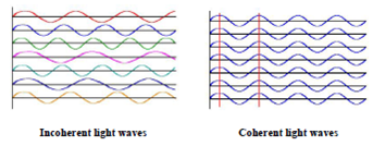
Highly Directional and Collimated:
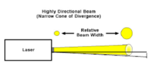
Lasers emit light that is highly directional, narrow beam divergence. The light from laser emerges in an extremely thin beam with very little divergence therefore the beam is also highly collimated. The high degree of collimation arises from the fact that the cavity of the laser has very nearly parallel
front and back mirrors which constrain the final laser beam to a path which is perpendicular to those mirrors. As a result, laser beams are very narrow and do not spread very much. Angle of divergence  ,where D is diameter of beam
1. Welding and Cutting: The highly collimated beam of a laser can be focused to a microscopic dot of extremely high energy density for welding and cutting. The automobile industry makes extensive use of carbon dioxide lasers with powers up to several kilowatts for computer-controlled welding on auto assembly lines.
2. Communication: The lasers have significant advantages in communication because they are more nearly monochromatic and this allows the pulse shape to be maintained better over long distances when used in optical fibre.
3. Barcode Scanner: Supermarket scanners typically use helium-neon lasers to scan the universal barcodes to identify products. The laser beam bounces off a rotating mirror and scans the code, sending a modulated beam to a light detector and then to a computer which has the product information stored.
4. Laser Printing: The laser printer has in a few years become the dominant mode of printing in offices. The laser is focused and scanned across a photoactive selenium coated drum where it produces a charge pattern which mirrors the material to be printed. This drum then holds the particles of the toner to transfer to paper which is rolled over the drum in the presence of heat.
5. CD’s and Optical Discs: The detection of the binary data stored in the form of pits on the compact disc is done with the use of a semiconductor laser.
6. Surveying and Ranging: Helium-neon and semiconductor lasers have become standard parts of the field surveyor's equipment. A fast laser pulse is sent to a corner reflector at the point to be measured and the time of reflection is measured to get the distance.
7. Laser cooling: The use of lasers to achieve extremely low temperatures has advanced to the point that temperatures of 10-9 K have been reached
8. Laser Spectroscopy: Laser spectroscopy has led to advances in the precision with which spectral line frequencies can be measured, and this has fundamental significance for our understanding of basic atomic processes.
9. Holography: Holography is "lens less photography" in which an image is captured not as an image focused on film, but as an interference pattern at the film.
10. Medicine: Lasers have been used for various medical procedures such as dermatology and cosmetic surgery, wound healings, nerve stimulation, dentistry ophthalmology applications for vision corrections and corneal deceases. And many other therapeutic procedures. Combining the nanoparticles, diode lasers have been also used for cancer therapy, bio-sensing, bio-imaging, drug delivery and diagnostics of cancer cells.
The optical fibre is a cylindrical, long, thin transparent structure made of glass and plastic, which is designed to guide the light wave from one end to another. The light inside the fibre is guided on the principle of Total Internal Reflection (TIR).
Optical fibers are widely used in fibre-optic communications to send information (data).
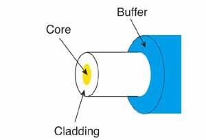
The basic structure of an optical fiber consists of three parts: the core, the cladding, and the coating or buffer which are coaxially arranged. The innermost region is called the core, the light in the fibre travels only in the core. The core is surrounded by cladding, which is responsible for keeping the light inside the core. The refractive index of core (n1) is greater than of cladding (n2). The outermost region is called buffer or sheath, which protects the core and cladding from external abrasions
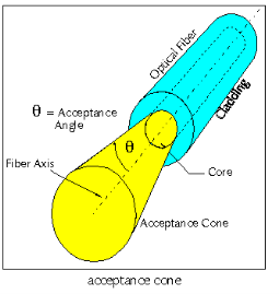
The acceptance angle of an optical fiber is defined based on a purely geometrical consideration (ray optics): it is the maximum angle of a ray (against the fiber axis) hitting the fiber core which allows the incident light to be guided by the core. The sine of that acceptable angle (assuming an incident ray in air or vacuum) is called the numerical aperture, and it is essentially determined by the refractive index contrast between core and cladding of the fiber, assuming that the incident beam comes from air or vacuum:

Here, ncore and ncladding are the refractive indices of core and cladding, respectively, and n0 is the refractive index of the medium around the fiber, which is close to 1 in case of air.
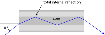
The largest Launch Angle of Incident Light that can propagate down the Fiber optics
Numerical Aperture (NA)
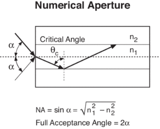
The Numerical Aperture (NA) of a fibre is defined as the sine of the largest angle an incident ray can have for total internal reflectance in the core. Rays launched outside the angle specified by a fibber’s NA will excite radiation modes of the fiber. A higher core index, with respect to the cladding, means larger NA. However, increasing NA causes higher scattering loss from greater concentrations of dopant. A fiber's NA can be determined by measuring the divergence angle of the light cone it emits when all its modes are excited.
Qualitatively, NA is a measure of the light gathering ability of a fiber. It also indicates how easy it is to couple light into a fiber.
The communication system of fiber optics is well understood by studying the parts and sections of it. The major elements of an optical fiber communication system are shown in the following figure.
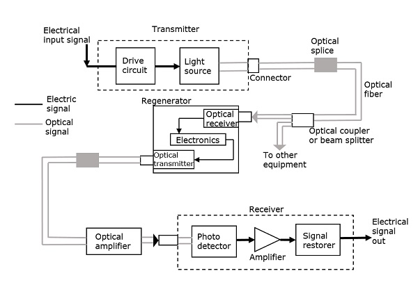
The basic components are a light signal transmitter, the optical fiber, and the photo detecting receiver. The additional elements such as fiber and cable splicers and connectors, regenerators, beam splitters, and optical amplifiers are employed to improve the performance of the communication system.
Functional Advantages
The functional advantages of optical fibers are −
● The transmission bandwidth of the fiber optic cables is higher than the metal cables.
● The amount of data transmission is higher in fiber optic cables.
● The power loss is very low and hence helpful in long-distance transmissions.
● Fiber optic cables provide high security and cannot be tapped.
● Fiber optic cables are the most secure way for data transmission.
● Fiber optic cables are immune to electromagnetic interference.
● These are not affected by electrical noise.
● Medical
Used as light guides, imaging tools and also as lasers for surgeries
● Defence/Government
Used as hydrophones for seismic waves and SONAR, as wiring in aircraft, submarines and other vehicles and also for field networking
● Data Storage
Used for data transmission
● Telecommunications
Fiber is laid and used for transmitting and receiving purposes
● Networking
Used to connect users and servers in a variety of network settings and help increase the speed and accuracy of data transmission
● Industrial/Commercial
Used for imaging in hard to reach areas, as wiring where EMI is an issue, as sensory devices to make temperature, pressure and other measurements, and as wiring in automobiles and in industrial settings
● Broadcast/CATV
Broadcast/cable companies are using fiber optic cables for wiring CATV, HDTV, internet, video on-demand and other applications
Fiber optic cables are used for lighting and imaging and as sensors to measure and monitor a vast array of variables. Fiber optic cables are also used in research and development and testing across all the above-mentioned industries.