Module 3
Light And Optics
The Fresnel equations define the reflection and transmission of light (or electromagnetic radiation in general) when incident on an interface amiddissimilar optical media.
Light is a “transverse wave” expected by Fresneleven most of understood that the "vibrations" of the wave were electric and magnetic fields.
For the first time, polarization might be expected quantitatively, as Fresnel's equations suitablyexpectable the differentact of waves of the s and p polarizations example upon a material interface.
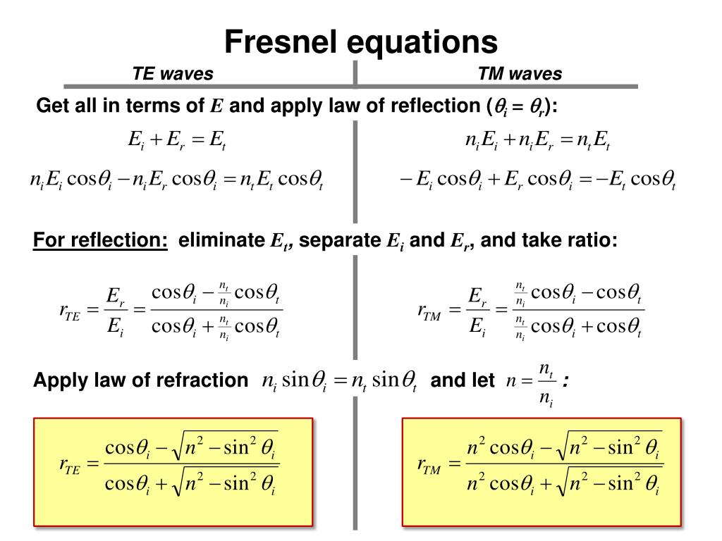
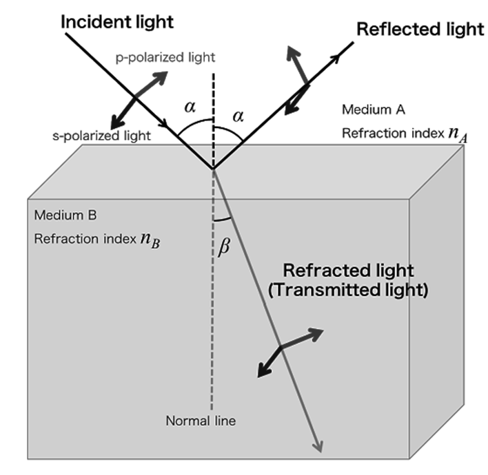
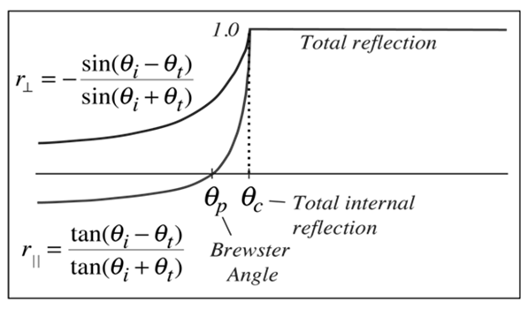
Usual reflection and transmission curves for outside reflection. These curves are the graphical picture of the Fresnel equations. Note that the reproduced amplitude for the light polarized parallel to the incident plane is zero for a specific angle called the “Brewster angle”.
The reflected light is then linearly polarized in a plane perpendicular to the incident plane. This polarization by reflection is broken in frequent optical devices.
Internal Reflection Curves
The above figure shows reflection curves for “internal reflection”. Internal reflection indicates that the reflection is from an interface to a medium of lesser index of refraction, as from water to air.
These curves are the graphical image of the Fresnel equations. Note that the reflected amplitude for the light polarized parallel to the incident plane is zero for a specific angle known as the Brewster angle.
The reflected light is then linearly polarized in a plane perpendicular to the incident plane. This polarization by reflection is exploited in common optical devices.
Another illustrative of internal reflection is that there is continually an angle of incidence qc above which all light is reflected back into the medium. This phenomenon of total internal reflection has many practical presentations in optics.
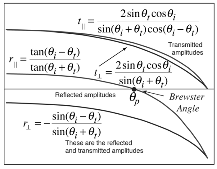
Brewster's angle (similarlyrecognized as the polarization angle) is an angle of incidence at which light with a specific polarization is naturally transmitted over a transparent dielectric surface, with no reflection.
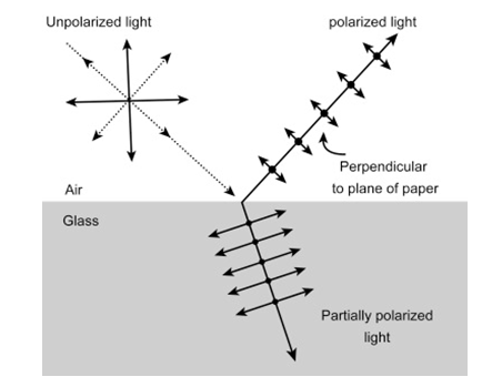
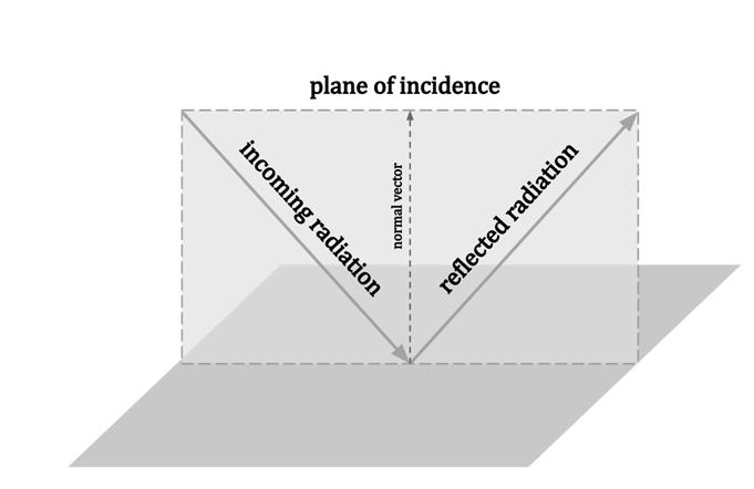
For finding vanishing reflection losses at a Brewster plate, the angle of incidence has to be close to Brewster's angle, and the light must be p-polarized, i.e., the polarization direction is in the plane of incidence.
When light finishes on a flat boundary amid two different transparent medium, typically at least roughly part of its optical power is reflected.
Conversely, for a particular angle of incidence, which is called Brewster's angle sometimes polarizing angle, that reflection does not happen provided that the light is p-polarized. On behalf of s-polarized light, the reflectivity is uniformgreater than for light with normal incidence on the boundary.
The magnitude of Brewster's angle depends on the refractive indices of the involved optical media and can be considered with Brewster's law:

Here, n1 and n2 are the refractive indices of the medium of the received beam and the other medium, separately. One can show that the sum of the angles in both media (relative to the direction for normal incidence) is 90°.
As a numerical example, one can consider light coming from air (n1 ≈ 1) to a glass with n2 = 1.5. For that situation, one can determine that Brewster's angle is ≈56.3°. Above diagram shows Brewster's angle as a meaning of the ratio of refractive indices or the refractive index () of the second medium, if the first medium must have n1 = 1.
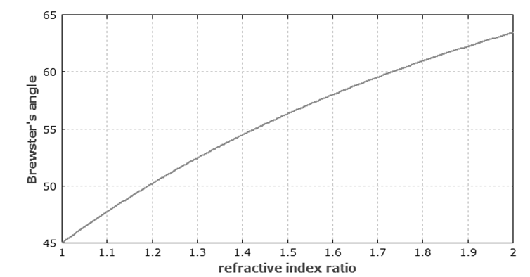 Figure: Dependence of Brewster's angle on the ratio of refractive indices of the media.
- For interfaces between media with similar refractive indices, Brewster's angle is close to 45°. Reflections are anyway weak in such cases.
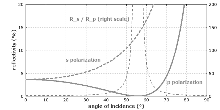 Figure: Dependence of the power reflectivity on the angle of incidence, if the light at 1064 nm wavelength imposes from air on a silica surface.
- Usually, reflectivity’s at such surfaces can be calculated using Fresnel equations. With that, one can for example calculate the effective reflectivity for a laser beam with finite divergence as a weighted average of reflectivities for different angular components.
- Generally, such effective reflectivity’s are rather small, because most laser beams have a small divergence.
- For a qualitative understanding of the disappearing reflectivity, one can study the oscillating electric polarization in the second medium, which is perpendicular to the direction of the disappearing reflected beam.
- It is well known that dipoles do not emit radiation accurately in the direction of their oscillation. Though, that picture is not provided that a real explanation; for example, it is not clear why the direction of electric polarization in the second medium should be related, although the reflected beam would propagate in the first medium.
- “Total internal reflection” is the optical phenomenon in which the surface of the water in a fish-tank when observed from below the water level, reflects the underwater sight like a mirror, with no loss of brightness.
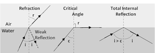
Within a medium such as water or glass from the surrounding surfaces back into the medium. The phenomenon happens if the angle of incidence is greater than a certain limiting angle, called the “critical angle”.
In general, total internal reflection takes place at the boundary amid two transparent media when a ray of light in a medium of higher index of refraction methods the other medium at an angle of incidence greater than the critical angle.
Air-watersurface’s critical angle is 48.5°. Since indices of refraction depend on wavelength, the critical angle (and hence the angle of total internal reflection) will vary somewhat with wavelength and, so, with color.
At all angles less than the critical angle, both refraction and reflection happen in variableamounts.
Evanescent field
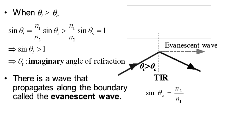
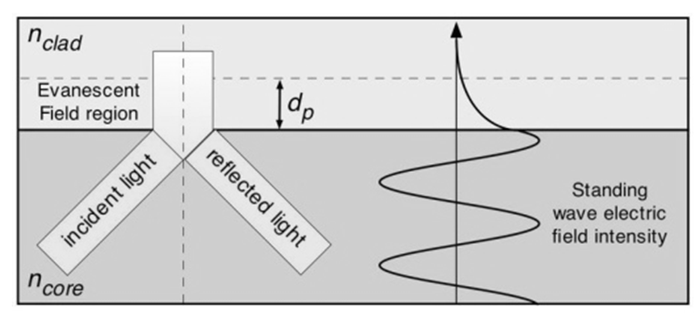
In electromagnetics an evanescent field or evanescent wave is wavering electric and magnetic field that does not propagate as an electromagnetic wave but whose energy is spatially focused in the nearby area of the foundation (oscillating charges and currents)
Optical instruments are based on optics. The light microscope and telescope usage convex lenses and mirrors to mark enlarged images of actual tiny or distant objects.
A camera usage a convex lens to make a condensed image of an object.
A lens is anactual device with two curved surfaces, typically made of glass or plastic, that uses refraction to form an image of an object.
Mirrors, which have curved surfaces intended to reflect rays, also form images.
A system of lenses and mirrors forms an image by meeting rays from an object and then sources them to converge or diverge. The position to which the rays converge to or diverge from is the image.
A real image is made when the optical system sources the rays to converge to a point, a virtual image is made at the location from which they seem to invent.
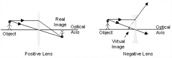
Representations of lenses forming real and virtual images. Positive and negative lenses can mutually form real and virtual images.
The properties of lenses and mirrors on a ray can be determined using Fermat’s Principle, through trigonometry and the presentation of Snell’s Law, to trace the path of a light ray from a point on the source to the image point. This is done by
1) Outlining a ray from the object to the first surface of the lens by means of trigonometry,
2) determining how the ray refracts at the first interface using Snell’s Law,
3) tracing the ray to the second interface using trigonometry,
4) figuring out how it refracts at this surface using Snell’s Law,
5) then tracing the ray to the image location using trigonometry.
At minimum two rays from each basis point should be traced to regulate the position of the image point. A matrix technique based on these rules is often used to mathematically control how rays propagate over an optical system.

Sketch showing the steps taken when spreading a ray through an optical system.
In general, the curvature of one side of the lens is dissimilar than that of the other side of the lens. The curvature of a lens surface is the inverse of the radius of curvature of the surface (c = 1/R).
The curvature is positive when the center of curvature is to the right of the surface and negative when the center of curvature is to the left of the surface. Lenses or mirrors with flat surfaces are said to have an infinite radius of curvature.
s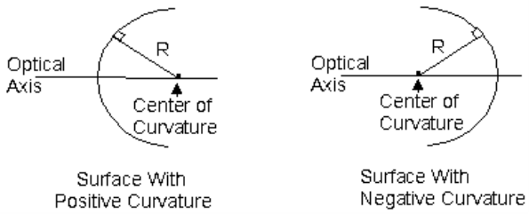
Surfaces having positive and negative curvatures. R is the radius of curvature and c = 1/R is the curvature of the surface.
Though it is possible to buy lenses that have aspherically curved surfaces, the massivepopular of lenses have spherically curved surfaces.
Maximum optical systems use spherical lenses since they are easier to make and inexpensive to buy than aspherical lenses.
Lens creatorsstipulate the curvatures, the thicknesses, and the refractive indices of the lenses to regulate the way that lenses image objects.
For a lens that has a very minor thickness, called a thin lens, it is a good estimate to say that the lens has NO thickness. In this case, it is not essential to propagate the ray from the first surface of the lens to the second.
The outcome of the lens be subject to only on the difference in curvature of the two lens surfaces, so dissimilar thin lenses can have the same power.
Thin lens Power in air is given by,
f = (c1-c2) (n-1).
The focal length of that same thin lens in air is
f = 1/f.
The focal length of a thin lens is the distance amid the lens and the point at which the lens affects a ray, which remainedinitially traveling parallel to optical axis to meet the optical axis.
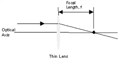
Focal length of a thin lens
If a base is located very far away from a lens, all of the rays receiving that lens will be closely parallel to one and more. If the source is an infinite distance away, the rays will be totally parallel to one another.
A packet of rays for this kind might be used to find the focal length of a thin lens; the lens would focus them all down into one spot that would be informal to find. Lasers can be made to emit this kind of light.
A simple arrival that labels how a thin lens images an object is called the Thin Lens Equation.
It is a right way to figure out the location of an image if the distance amid the object and the lens and the focal length of the lens are recognized. This equation accepts that air surrounds the object, image, and lens.
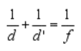
Thin Lens Equation
The image will not essentially be the same size as the object. The size of the image is found by multiplying the size of the object by the magnification of the system. The magnification of the thin lens system is

himage = m hobject
If the magnification is negative, then the image is inverted with respect to the object.
Mirrors can also be used to form images. They have a variation of curved surfaces, depending on their utility. Popular shapes of telescope mirrors are paraboloids, hyperboloids, and prolate ellipsoids.
Mirrors are extensively used in telescope schemessince they do not suffer from chromatic aberrations.
One of the challenges in designing telescopes is to develop an optical system that images points off of the optical axis as well as it does objects on the optical axis. This is the same as saying that the designers are working to increase the field-of-view of the telescopes.
The Hubble space telescope has the form of a Ritchey-Chretien Telescope. This telescope increases its field-of-view by using a hyperboloid as both primary and secondary mirrors.
The grouping of the two mirrors are needed to form a good image, unlike other telescope designs which use a single paraboloid mirror to form a good image and a secondary mirror to through the image to an eye or other detector.
Astronauts had to mount other optics in the Hubble as a way to exact for a defect in the curvature of the primary mirror that occurred during manufacturing.
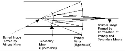
Ritchey-Chretien telescope
Although many telescopes are made using mirrors, there are some that are made using lenses. The Keplerian Telescope is one of them.
This telescope forms an inverted, internal image. Most binoculars are grounded on this design, and they use reflecting prisms to reinvert the image so that the image seems upright.

Keplerian telescope
Reference:
1. G. MAIN, “VIBRATIONS AND WAVES IN PHYSICS”, CAMBRIDGE UNIVERSITY PRESS,1993.
2. H. J. PAIN, “THE PHYSICS OF VIBRATIONS AND WAVES”, WILEY, 2006.
3. E. HECHT, “OPTICS”, PEARSON EDUCATION, 2008.
4. A. GHATAK, “OPTICS”, MCGRAW HILL EDUCATION, 2012.
5. O. SVELTO, “PRINCIPLES OF LASERS”, SPRINGER SCIENCE & BUSINESS MEDIA, 2010.