Unit - 2
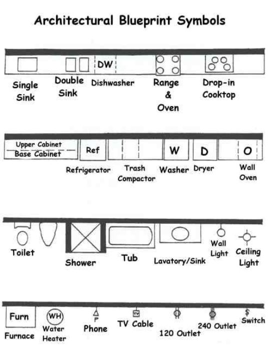
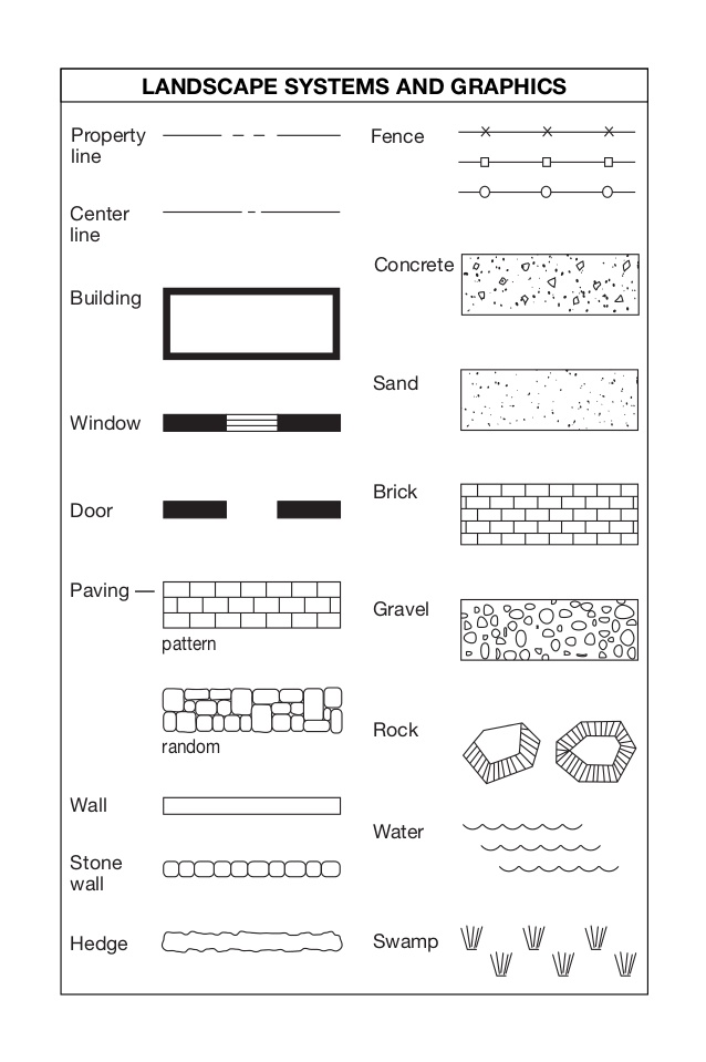
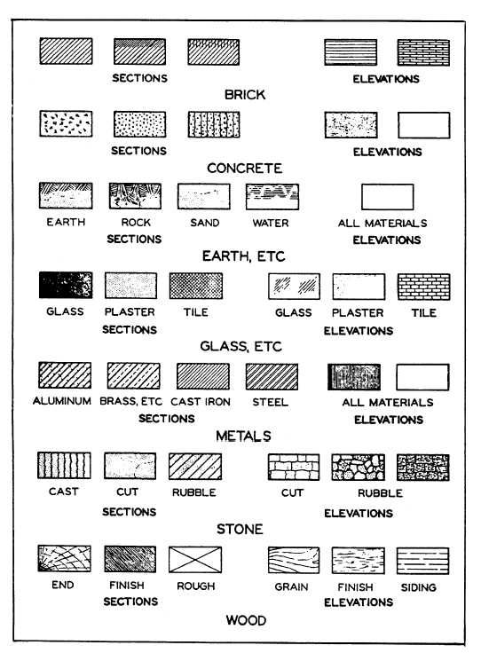
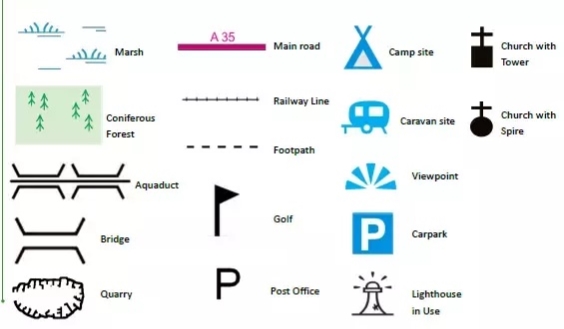
Symbols and Sign Conventions
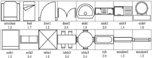
2.3 Structural
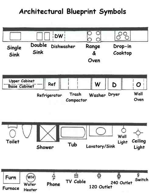
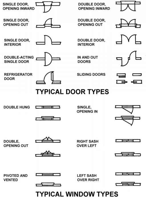
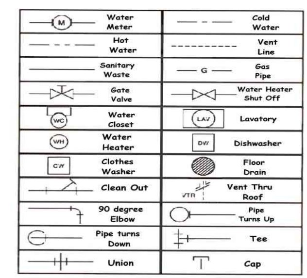
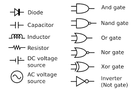
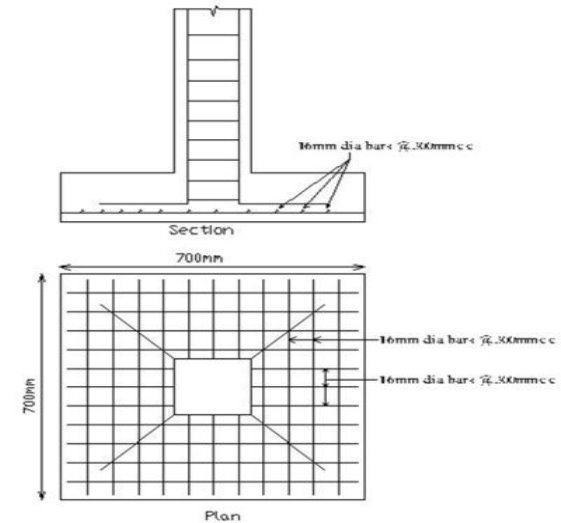
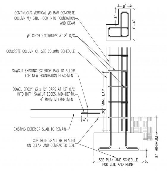
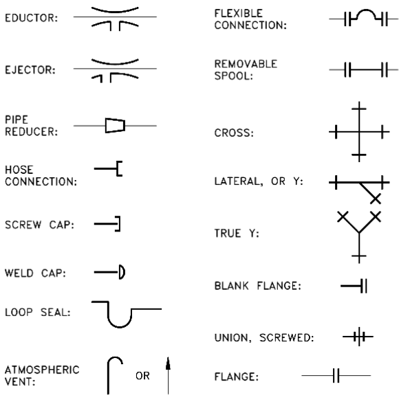
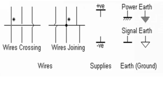
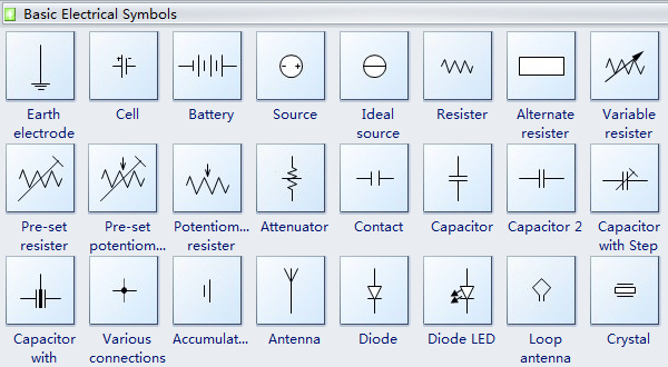
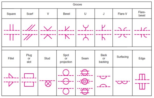
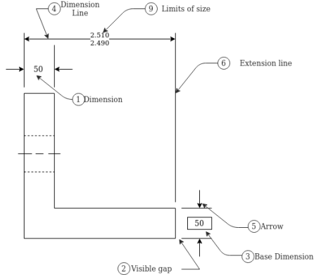
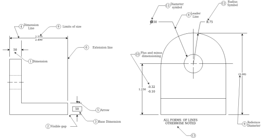
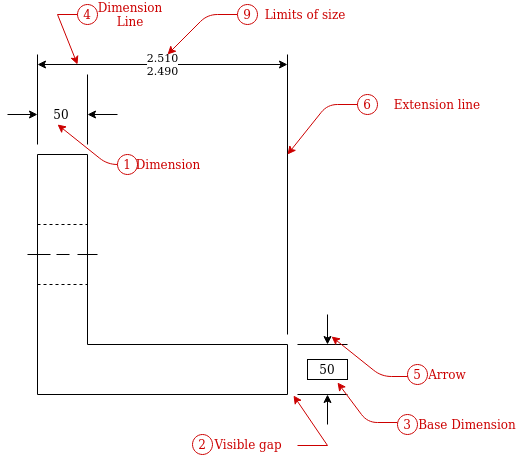
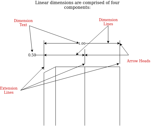
• The dimension is the numerical value that is being assigned to the size, shape or location of the feature being described.
• Dimension lines are thin lines that show the extent and direction of the dimension.
Arrowheads are placed at the ends of the dimension line. The dimension line is normally broken to insert the dimension.
• Extension lines are drawn perpendicular to the dimension line and associate the dimension with a particular feature or location.
Extension lines should not touch the object lines - there should be a visible gap between the extension line and the object line.
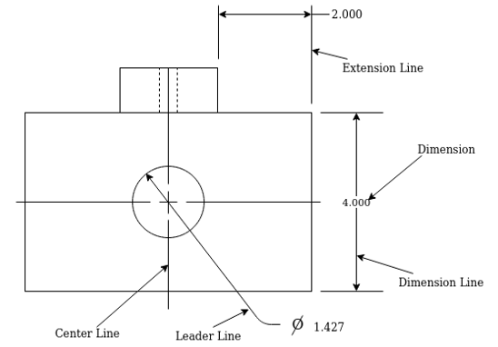
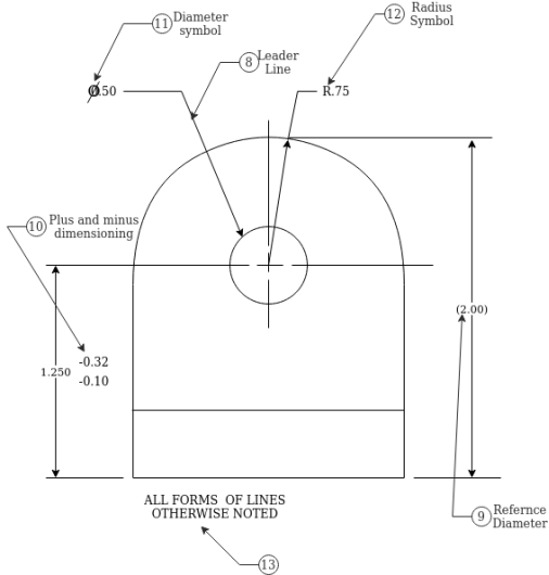
• A leader line is a thin solid line that is used to associate a note, symbol or dimension with a feature.
Leader lines are typically used to call out radii and diameters.
• A centre line is a light broken line used to indicate the center line of a feature.
References:
1. Subhash C Sharma & Gurucharan Singh (2005), “Civil Engineering Drawing”, Standard Publishers
2. Ajeet Singh (2002), “Working with AUTOCAD 2000 with updates on AUTOCAD 200I”, Tata- Mc Graw- Hill Company Limited, New Delhi
3. Sham Tickoo Swapna D (2009), “AUTOCAD for Engineers and Designers”, Pearson Education
4. Venugopal (2007), “Engineering Drawing and Graphics + AUTOCAD”, New Age International Pvt. Ltd.
5. Balagopal and Prabhu (1987), “Building Drawing and Detailing”, Spades publishing KDR building, Calicut
6. (Corresponding set of) CAD Software Theory and User Manuals.
7. Malik R.S., Meo, G.S. (2009) Civil Engineering Drawing, Computech Publication Ltd New Asian. Sikka, V.B. (2013), A Course in Civil Engineering Drawing, S.K.Kataria& Sons.
