Module I
Water & Water Treatment
Water
There are two types of Sources of Water:
a) Surface Sources
- Oceans, ponds, rivers, lakes, streams etc
b) Sub-surface Sources
- Infiltration Galleries
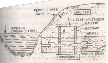
Figure 1: Cross-section of an Infiltration Gallery
Horizontal wells constructed at shallow depths of 3-5m
Generally constructed of masonry walls with roof slabs
Extract water from acquifer by various porous natural drain pipes located at regular intervals
Q =  (H2 – h2) where,
Q = discharge from Infiltration Galleries (m3/sec)
K = coefficient of permeability
R = radius
L = horizontal length of the gallery
H = height of water in gallery above datum
h = height of water on pumping equilibrium
- Springs
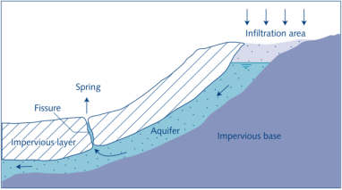
Figure 2: Springs
Gravity/ Non-artesian Springs: Natural outflow of water at ground surface
Artesian Springs: when ground water is trapped between two impervious strata of soil, pressure develops and water is forced out to the ground in the form of springs
- Acquifers
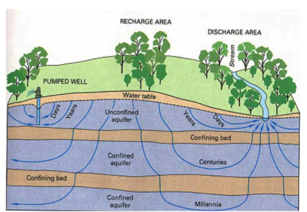
Figure 3: Confined & Unconfined Acquifers
An aquifer is an underground layer of water-bearing permeable rock, rock fractures or unconsolidated materials. Groundwater can be extracted using a water-well.
Confined Acquifer: an aquifer below the land surface that is saturated with water such that layers of impermeable material are both above and below the aquifer, causing it to be under pressure so that when the aquifer is penetrated by a well, the water will rise above the top of the aquifer.
Q =  (
( -
-  ) where,
Q = discharge from Confined Acquifer (m3/sec)
K = coefficient of permeability
r1 = distance of section 1-1 from the center of the well
r2 = distance of section 2-2 from the center of the well
h1 = height of water at section 1-1
h2 = height of water at section 2-2
Unconfined Acquifer: an acquifer where groundwater is in direct contact with the atmosphere through the open pore spaces of the overlying soil or rock
Q =  (
( -
-  ) where,
Q = discharge from Confined Acquifer (m3/sec)
K = coefficient of permeability
r1 = distance of section 1-1 from the center of the well
r2 = distance of section 2-2 from the center of the well
h1 = height of water at section 1-1
h2 = height of water at section 2-2
B = depth of impervious strata
- Infiltration Wells
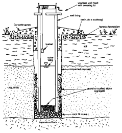
Figure 4: Infiltration Wells
A vertical hole of large diameter construction below ground level to pull up water to the surface
Open Well: limited yield as excavated to shallow depth
Q = KiA where,
K = coefficient of permeability
i = hydraulic gradient based on Darcy’s Law
A = area
Dug Well: high yield as excavated to larger depth
For any water body to function adequately, it must have certain degree of purity. Drinking water should be of highest purity. As the demand for water is fast approaching the available supply, the concept of quality of water is becoming as important as its quantity.
Each water use has specific quality need. Therefore, it is essential to identify the uses of water in a water body. In India, the Central Pollution Control Board (CPCB) has developed a concept of designated best use. According to this, out of the several uses of water of a particular body, the use which demands highest quality is termed its designated best use. Five designated best uses have been identified.
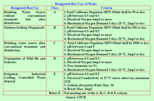
Figure 5: Designated Best used of Water according to CPCB
Furthermore, a color coding for water is done to depict its quality and showcase it’s availability on the maps. This standard specifies the acceptable limits and the permissible limits in the absence of alternate source. It is recommended that the acceptable limit is to be implemented as values in excess of those mentioned under ‘Acceptable’ render the water not suitable. Such a value may, however, be tolerated in the absence of an alternative source. However, if the value exceeds the limits indicated under ‘permissible limit in the absence of alternate source’ the sources will have to be rejected.

Figure 6: Colour Coding of Water according to CPCB
In India, CPCB has identified water quality requirements in terms of a few chemical characteristics, known as primary water quality criteria. Further, Bureau of Indian Standards has also recommended water quality parameter for different uses in IS 2296:1992. Guidelines are available to evaluate quality of water for irrigation. Furthermore, drinking water standards are discussed in IS 10500: 1991. Some of these parameters are given in the table below:
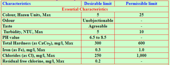
Figure 7: Essential Characteristics of Drinking Water according IS 10500:1991
A Water Quality Index (WQI) may be defined as a rating, reflecting the composite influence of different water quality parameters on the overall quality of water.
The main objective of computing of WQI is to turn the complex water quality data into information which is easily understandable and usable.
It can be use specific (industrial, municipal, irrigation, ecological).
WQI transforms vast & complex water quality data into a single number for the ease of understanding.
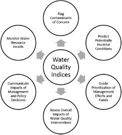
Figure 8: Steps to achieve WQI

Figure 9: WQI Values & Water Quality Rating as per National Sanitation Foundation
A water safety plan (WSP) is a plan to ensure the safety of potable water through comprehensive risk assessment & management at all steps in a water supply chain, starting from the catchment to the consumer.
WHO recommends water safety plans (WSPs) as the most effective means of consistently ensuring the safety and acceptability of a drinking-water supply. Their use ensures that water is safe for all forms of human consumption (drinking, washing, cooking etc) and that it meets regulatory water standards relating to human health. It is a way to ensure safe water by:
- Thoroughly understanding the systems in the property
- Identifying where and how problems could arise
- Using processes and management systems to stop the problems before they happen
- Making sure all parts of the system work properly
- A comprehensive risk assessment and risk management approach
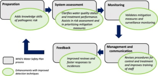
Figure 10: Components of a Water Safety Plan
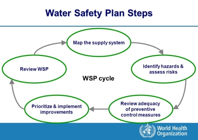
Figure 11: Steps of a Water Safety Plan
Steps in WSP
- Map the Supply System by making a flow chart etc
- Identify Risks through a ranking system
- Review Control Measures through validation, operational monitoring etc
- Implement Improvements through a prioritized schedule
- Review WSP through audits
WSPs are adaptable to all types and sizes of water supply, and can be effectively applied in all socio-economic settings. The water safety planning approach is increasingly being adopted globally as best practice for the provision of safe drinking-water.
Water Supply System
Water is present in abundant quantities on the Earth’s surface, but not more than 1 percent of the total available water is in the form of liquid fresh water. Most of Earth’s water (1.4 billion cubic km) is in the oceans or frozen in polar ice caps and glaciers. However, ocean water contains about 35 gm/l of dissolved minerals or salts, making it unfit for drinking, industrial or agricultural uses.
Fresh water, containing less than 3 gm/l of salts, is not uniformly distributed over the globe, resulting in water scarcity. In many locations, the availability of good-quality water is further reduced because of urban development, industrial growth, and environmental pollution.
In order to ensure the availability of sufficient quantity of good quality water, it is imperative to plan and build suitable water supply schemes, which will provide portable water to the various sections of the society in accordance with their demands and requirements. Hence, each country has developed certain Water Supply Schemes to ensure that good quality potable water is available to its citizens.
Types of Water Demand
- Domestic Water Demand
This demand is generally 50-60% of the total water demand. It is the demand of water required to satisfy the needs of cooking, drinking, bathing etc.
Strata of Society | Requirement (litres per capita per day – lpcd) |
Low Income Group Colonies | 135 |
Developed colonies with full flushing system | 200 |
Maximum Usage | 225 |
2. Industrial Water Demand
This demand is associated with the amount of water required for industrial needs.
Range: 50 to 450 lpcd
3. Institutional Water Demand
This demand is associated with the demand of water in colleges, hospitals, schools, stations and airport.
Range: 20 to 50 lpcd
4. Water required for Public Use
This includes washing of roads, public gardening etc. It is 5-6% of total water demand.
5. Fire Demand
This includes water required in case of fire break-out. It is generally taken as 1 lpcd or is calculated empirically as:
a) National Fire Board Formula
Q = 4637  [1 – 0.01
 ]
]
b) Kuchiling’s Formula
Q = 3182 
c) Freeman’s Formula
Q = 1136 [ + 10]
+ 10]
d) Buston’s Formula
Q = 5663 
Here, Q = Fire Demand in liters/min
And P = Population in thousands
6. Losses & Thefts
This includes water losses such as leakage & water thefts. It is generally 10-15% of the total water demand.
TOTAL WATER DEMAND = 335 lpcd (as per IS Code on Raw Water)
Factors affecting Water Demand
- Size of the City
- Climatic condition
- Types of Gentry & Habits of People
- Industrial Activities
- Quality of Water Supplies
- Pressure in the Distribution System
- Development of Sewage Facilities
- System of Supply
- Cost of Water
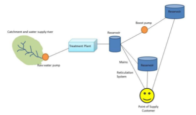
Figure 12: Components of a Water Supply System
- The starting point of the system is the catchment area where the rain falls and springs discharge groundwater to collectively form a reservoir or the source of water supply.
- Water is pumped from the source and piped to the water treatment plants.
- The treatment plant removes all the dirt and contamination. Chlorine is added to make the water safe for drinking and other purposes.
- Pipes are used to move the water to reservoirs, where the treated water is stored.
- From the reservoirs, the water is piped through the reticulation system to homes, businesses and other water users around the town.
- The Municipality’s system ends at the outlet side of the water meter, known as the point of supply.
- After that the home/business owner is responsible to obtain the water supply.
Methods of Water Distribution
The different methods of water distribution are discussed as follows:
a) Gravity Supply System
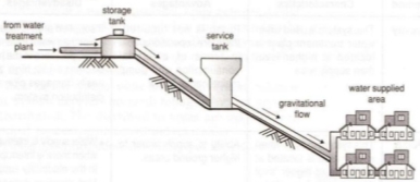
Figure 13: Gravity Supply System
- Suitable when water source is at a sufficient height
- Most reliable and economical water distribution system
- Water head available at the consumer end is just minimum required as remaining head is consumed in frictional & other losses
b) Pumping Supply System
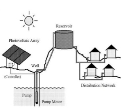
Figure 14: Pumping Supply System
- Treated water is pumped into the distribution mains without being stored in tanks
- High lift pumps are required to lift the water
- If power fails, water is not available for use
c) Combined Supply System

Figure 15: Combined Supply System
- Widely used supply system
- Water is pumped & stored in an elevated reservoir and is supplied to users under the action of gravity after being treated
- Excess water gets stored in reservoirs during low demand periods and can be used during high demand periods
- Economical, efficient and reliable method
System of Water Supply
Water can be supplied to consumers using two systems:
a) Continuous Supply: Water is supplied to the consumers 24 hours a day, every day of the year through a transmission and distribution system that is continuously full and under positive pressure.
Advantages:
- Water is not stagnant in the pipes at any instant and fresh water is continuously available
- Pipes of smaller diameter suffice the water demands
- Water is easily available for fire-fighting purposes
Disadvantages:
- Large volume of water is wasted even during minor leakages in pipes etc
- Higher amount of water is required at the source to maintain a continuous supply
- Higher wastage of water due to lack of civic sense
b) Intermittent Supply: If plenty of water is not available, supply of water is divided into zones and each zone is supplied with water for a fixed number of hours in a day i.e., the water is supplied in intervals.
Advantages:
- Restrained supply hours & reduced pressure can limit leakage losses
- Helpful in balancing the scarcity of water resource
- Sufficient time is available for repair and maintenance of pipelines
Disadvantages:
- Systems do not operate as designed as many components go underused and others are overused and exploited
- Inconvenient for consumers as they need to store water between supplies
- Stored water is thrown when fresh water comes, causing higher wastage
- Pipelines are subjected to vacuum conditions after supply hours which can cause groundwater infiltration into the pipelines leading to contamination of water
Layout of Water Distribution Network
- Dead End or Tree System
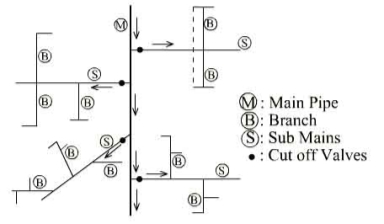
Figure 16: Dead End System
Features:
a) There is one main supply pipe that runs through the centre of the populated area and sub-mains branch off from both sides.
b) The sub-mains divide into several branch lines from which service connections are provided.
Advantages:
a) Simple design calculations as it is possible to determine discharge and pressure in each pipe very accurately
b) Cheap & economical as the diameters of pipes of main, sub mains and branches can be designed as per requirement
c) Easy to lay system of pipes
d) Lesser number of cut-off valves are required
Disadvantages:
a) One main pipeline in the entire city is quite risky as water supply may completely stop in case of any failure in this pipeline
b) Large number of valves are required
c) Constant pressure is not maintained
d) Fire-fighting discharge is not available
e) Dead ends might affect the quality of water by allowing sedimentation and encouraging bacterial growth due to stagnation
f) Water hammer effect at the dead ends could cause bursting of pipes
2. Grid Iron System
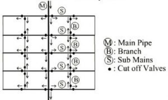
Figure 17: Grid Iron System
Features:
a) Dead ends are eliminated by inter-connecting all the lines
b) The water flows continuously in this system without stagnating
c) This system is more suitable for well-planned rectangular cities
Advantages:
a) The water will flow continuously without any dead ends causing sediment deposits or water hammer effect
b) Head loss is minimum in this case because of the inter-connecting pipes
c) Sufficient discharge will be available for fire-fighting
d) Repair works can be carried out by closing the cut-off valve in the affected line without hampering the supply to other parts of the city
Disadvantages:
a) The pipes used in this system should be of large diameters and longer lengths because of circulating flow from all directions
b) The design is difficult because we cannot determine the accurate discharge, velocity, or pressure in a particular pipe
c) More number of cut-off valves are required
3. Ring or Circular System
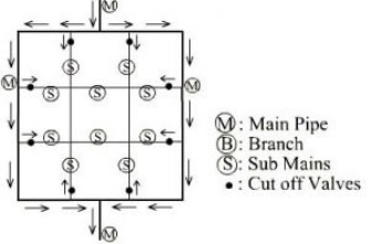
Figure 18: Ring or Circular System
Features:
a) A main pipeline is provided around the city and the branch lines are connected with each other and projected perpendicularly such that every street within the distribution area will get sufficient water supply from a number of pipes
b) This system is suitable for a town with well-planned streets and roads
c) This system is used with the grid iron system so as to enhance the capacity of the grid iron system
Advantages:
a) No stagnation of water occurs
b) Repair work can be carried out without affecting the larger network
c) A large quantity of water is available for fire-fighting
d) Improved pressure in the pipelines is obtained
Disadvantages:
a) Large diameter and longer length of pipes are required in this system
b) Skilled workers are required for laying down these pipes
c) Large number of cut-off valves
4. Radial System
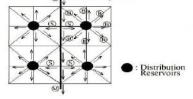
Figure 19: Radial System
Features:
a) The whole area is divided into small distribution zones and an individual reservoir is provided for each distribution zone
b) The pipelines are laid radially along the surrounding streets from this reservoir
Advantages:
a) Water is distributed at high pressure and at high velocity
b) Head loss is small because of quick discharge
c) Design calculations are simple
Disadvantages:
a) High cost of the project because of the number of individual distribution reservoirs
b) Stagnation of water occurs in pipes due to many dead ends
A valve is a type of fitting that allows for regulation, control, and direction of fluids passing through a pipe. Valves are commonly used to direct flow, shut off water access, prevent backflow, and adjust water pressure within a system.
- Ball Valves
- Used for flow and pressure control and can be shut-off for corrosive fluids, slurries, normal liquid and gases
- Used in the oil and natural gas industry, manufacturing sectors, chemical storage, and even residential buildings
- Open & close quickly
- Leak-proof
- Cost-effective
2. Gate Valves/ Cut-off Valves/ Sluice Valves/ Stop Valves
- Used to cut-off the main supply whenever required and hence helpful n dividing the water mains in to suitable sections
- Placed at street corners or at pipe intersections
- Very low friction & pressure losses
- May not be very durable and are susceptible to corrosion as they are made up of iron
- Cannot be opened & closed very quickly
3. Butterfly Valve
- Designed to regulate flow, but with limited control capability
- Are very accurate and are therefore used in pharmaceutical & chemical industries
- Reliable & low-maintenance
- Do not have tight shut-offs
4. Globe Valve
- Globe valves are used to throttle or limit the flow of water
- Opening-closing time is shorter
- Lesser leakage & can be used under high-temperature conditions
- High pressure losses
5. Check Valve/ Reflux Valve
- Prevent backflow
- Reduce water hammer forces on the pump
- Required at inter-connections between a polluted water system and a potable water system
6. Pressure Relief Valve
- Reduce water hammer pressure in pipes
- Open automatically as soon as the pressure in pipes exceed a certain limit, allow some water to flow out and thus reduce the pressure
- Useful in small pipelines
7. Blow-off Valve/ Drain Valve/ Scour Valve
- Used to remove entire water from within the pipe for inspection & repair purposes
- Provided at low points for removal of silt etc
Features
- Storage Reservoirs are also known as Service Reservoirs or Distribution Reservoirs
- They are used to store the treated water during low-demand periods so that it can be utilised during emergencies and high-demand periods
Functions
- Help to absorb hourly variations in demand
- Help to maintain constant pressure in the distribution mains
- Provide water supply during emergencies
Location & Height
- Should be located as close as possible to the centre of the demand
- Should be at a sufficient elevation to allow gravity flow while maintaining adequate pressure
Types of Storage Reservoirs
- Surface Reservoirs or Ground Reservoirs
Rectangular or circular in shape
Constructed on high natural ground with plinth level not more than 3m and may be made of RCC, stones, bricks
Side walls are designed to take up the water pressure when the reservoir is full and earth pressure when the reservoir is empty
Bitumen compounds are used at all joints to ensure water tightness
At the top of the roof, 60cm thick earth layer is deposited and green lawns are maintained to protect the reservoir from temperature fluctuations
Ventilation pipes are provided to ensure circulation of air
Stairs are provided for repair & maintenance works
- Elevated Reservoirs or Overhead Tanks
Constructed at a height of more than 15m, sufficient to pressurize a water distribution system for the distribution of potable water
Adopted where combined gravity and pumping system of water distribution is adopted
May be made of steel or RCC
Ventilation pipes are provided to ensure circulation of air
Stairs are provided for repair & maintenance works
Consists of a float gauge to indicate depth of water
Has an automatic device to stop pumping when the tank is full
Design Capacity of Storage Reservoirs
Capacity of Storage Reservoirs is the summation of the following three factors:
- Balancing Storage: quantity of water required to be stored in the reservoir to balance the fluctuating water demand against a constant supply
- Breakdown/ Emergency Storage: storage required in times of emergencies posed by failure of pumps, electricity etc
A value of 25% of the total storage capacity of the reservoir or 1.5 to 2 times of the average hourly supply may be taken as Emergency Storage.
- Fire Storage: storage required for fire emergencies
A value of 1 to 4 lpcd (litres per capita per day) may be taken as Fire Storage.
Water Treatment
It is a process of providing oxygen from atmosphere into water for the following reasons:
a) Removal of bad taste & bad odour
b) Reduces corrosive property by expelling CO2
c) Removal of volatile solids (like phenol, benzene etc.)
Types of Aerators
a) Spray Towers
Construction:
- They consist of spray nozzles, which are connected in a pipe, located over an open-top tank.
- The water leaves each nozzle in a fine spray and falls through the surrounding air.
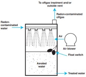
Figure 20: Spray Towers
Limitations:
- Require large installation area
- Difficult to operate in freezing weather
- Nozzle design is important in achieving optimum dispersion of water
- Short exposure time between water and air
b) Air Diffusers
Construction:
- Air is introduced into liquid being aerated in the form of bubbles which typically rise through the liquid.
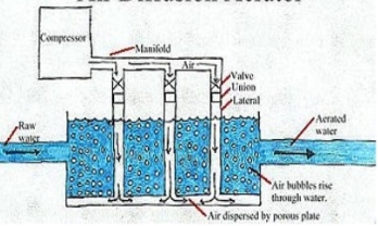
Figure 21: Air Diffusers
Limitations:
- Is not portable
- Higher capital cost
c) Cascade Aerator
Construction:
- Simplest free-fall aerator that looks like a water-fall designed manually so that water gets aerated while falling down the steps.
- It is based on the principle of gravity.
- Aeration of this type has more efficiency due high surface for contact with atmosphere.
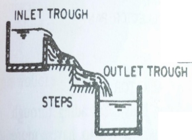
Figure 22: Cascade Aerator
Sedimentation is a natural process in which solids with higher density than the fluid in which they are suspended, settles under the action of gravity.
Detention Time = 4 to 8 hours
They are designed to reduce velocity and turbulence. It is of two types:
a) Plain Sedimentation
b) Sedimentation aided with coagulation
Settling velocity of particle in sedimentation tank is given by:
Vs =  where,
Vs = settling velocity of particle
Yw = density of water
G = specific gravity of water
µ = viscosity of water
d = particle size
Stage 1 - Coagulation: In order to increase the efficiency of sedimentation of very small size particles, we add certain coagulants to water.
Coagulants are certain chemical compounds added to water so as to neutralize the negative protective charge over the suspended particle in order to come in contact with each other and grow in size, thus gets easily settled by gravity.
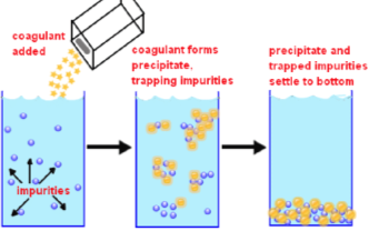
Figure 23: Coagulation
Commonly-used Coagulants
a) Alum [Al2(SO4)3.18H2O]: forms sticky gel type precipitate
b) Copperas [FeSO4.7H2O]
c) Chlorinated Copperas [Fe2.(SO4)3 + FeCl3]
d) Sodium Aluminate [Na2Al2O4]
Stage 2 – Flocculation: It is a process in which neutralized particles are brought in contact with each other, so as to increase the opportunity to combine, grow in size and settle down. Flocculation refers to the process by which fine particulates are caused to clump together into a floc.
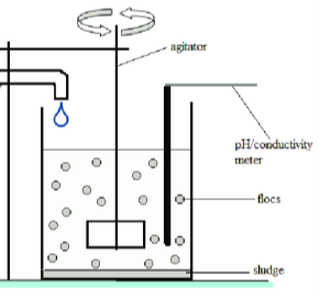
Figure 24: Flocculation
Rate of Flocculation depends upon
a) Turbidity
b) Type of dose of coagulant
c) Intensity of mixing
Filtration is the process in which fine suspended particles are removed from water which could not be removed in Primary Sedimentation Tank.
Filters also remove suspended solids along with organic matter, microorganisms and dissolved minerals.
Classification of Filters on the Basis of Head
- Gravity Filter: Head required to flow from filter media is provided by height of water itself.
- Pressure Filter: Head is provided artificially by applying pressure.
Classification of Filters on the Basis of Treatment Process
- Slow Sand Filter
- Rapid Sand Filter
The difference between these is tabulated in the figure below:
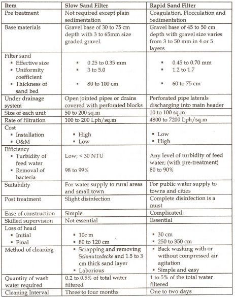
Figure 25: Difference between Slow Sand & Rapid Sand Filters
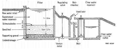
Figure 26: Slow Sand Filter
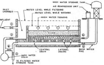
Figure 27: Rapid Sand Filter
It is the process of killing harmful micro-organisms in water either physically or mechanically.
Physical methods involve boiling, heating and use of UV radiation to remove the harmful microbes.
Chemical Methods:
- Treatment with Ozone
Under high voltage, ozone molecule may break down into oxygen molecule and nascent oxygen, because of its instability.
 O3 O2 + O
Nascent oxygen is a very powerful oxidising agent.
2. Chlorination
When chlorine is added to water, it forms hypochlorous acid (HOCl), which is one of the most powerful disinfecting agents of O2.
 Cl2 + H2O HOCl + HCl
Adsorption
- It is a wastewater purification technique for removing a wide range of compounds from industrial wastewater.
- It is most commonly implemented for the removal or low concentrations of non-degradable organic compounds from groundwater, drinking water preparation, process water etc.
- Adsorption takes place when molecules in a liquid bind themselves to the surface of a solid substance known as Adsorbents.
- Adsorbents have a very high internal surface area that permits adsorption.
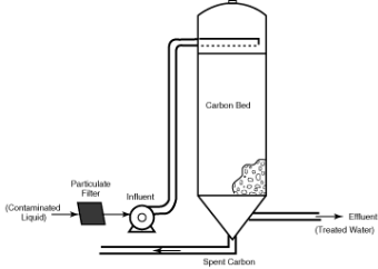
Figure 28: Adsorption
- Active carbon is the most widely used adsorbent. Other adsorbents are natural or synthetic zeolites, natural clay minerals, silica gel and activated aluminium.
Ion Exchange
- Ion exchange is a water treatment method where one or more undesirable ionic contaminants are removed from water by exchange with another non-objectionable, or less objectionable ionic substance.
- Both the contaminant and the exchanged substance must be dissolved and have the same type of electrical charge (positive or negative).
- It is efficient in removing toxic metals from water and is also used for the softening of water.
- Advantages:
One of the most appropriate technologies to removes dissolved inorganic ions effectively
Possibility to regenerate resin
Relatively inexpensive initial capital investment
- Disadvantages:
Does not remove effectively bacteria
High operation costs
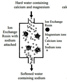
Figure 29: Ion Exchange
Membrane Process
- A membrane process is any method that relies on a membrane barrier to filter or remove particles from water.
- Fluid is passed through the membrane because of the pressure difference between one side of the membrane and the other. Contaminants remain on one side.
- Membrane Processes:
Forward osmosis
Reverse osmosis
Microfiltration
Ultra-filtration
Nano-filtration
- Membrane Types and Configurations
Membranes are thin barriers that allow water to pass through but stop unwanted substances from passing through with it. Membranes are made from polymer-based films, ceramics, and other materials.
Membranes can be isotropic or anisotropic. Isotropic membranes show a uniform composition and physical structure in cross-section, while anisotropic membranes are not uniform in cross-section. They generally are formed from differently structured layers and different materials.
Types of membranes in general use include tubular, hollow-fibre, and flat-sheet.
- Ideal Properties of Water Treatment Membranes:
Compactness
Low tangential flow resistance
Uniform velocity distribution
Easy maintenance and cleaning
Low unit cost
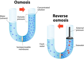
Figure 30: Osmosis & Reverse Osmosis using Membrane Filter Technique
Reference Books:
1) Santosh Kumar Garg -“Environmental Engineering (Vol. II) Sewage Waste Disposal and Air Pollution Engineering” – Khanna Publishers
2) Dr. K.N. Duggal- “Elements of Environmental Engineering” – S. Chand
Reference YouTube Video Links:
- Https://www.youtube.com/watch?v=kXCFFupDK0g&list=PLgzsL8klq6DIOpwb57vb_ha_IUyNKRUyS
- Https://www.youtube.com/watch?v=8C3ed5fiuaE&list=PLbCDLPSRuhSN5cpFvSCEpGFWHhcvT7gnT