UNIT-4
Transport Layer
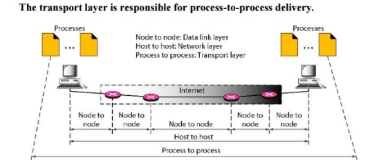
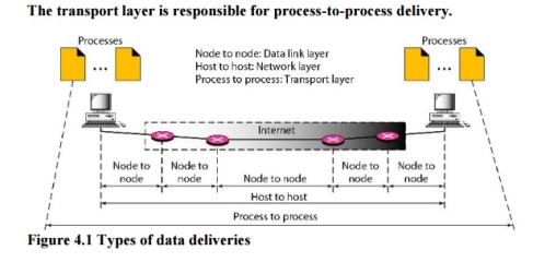
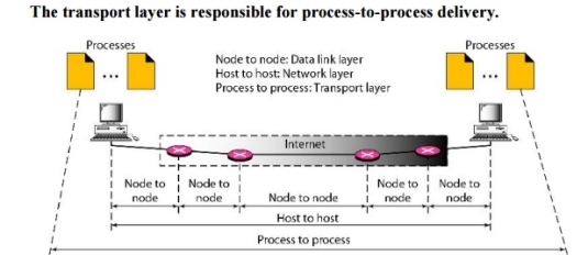
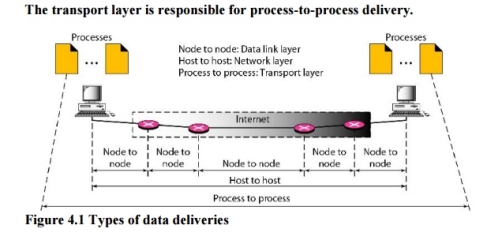
The data link layer is responsible for delivery of frames between two neighbouring nodes over a link. This is called node-to-node delivery. The network layer is responsible for delivery of datagrams between two hosts. This is called host-to-host delivery. Real communication takes place between two processes (application programs). We need process-to-process delivery. The transport layer is responsible for process-to-process delivery-the delivery of a packet, part of a message, from one process to another. Figure 4.1 shows these three types of deliveries and their domains
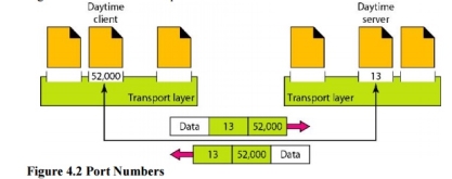
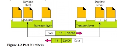
Fig 1 – Types of data deliveries 1. Client/Server Paradigm Although there are several ways to achieve process-to-process communication, the most common one is through the client/server paradigm. A process on the local host, called a client, needs services from a process usually on the remote host, called a server. Both processes (client and server) have the same name. For example, to get the day and time from a remote machine, we need a Daytime client process running on the local host and a Daytime server process running on a remote machine. For communication, we must define the following: 1. Local host 2. Local process 3. Remote host 4. Remote process 2. Addressing Whenever we need to deliver something to one specific destination among many, we need an address. At the data link layer, we need a MAC address to choose one node among several nodes if the connection is not point-to-point. A frame in the data link layer needs a Destination MAC address for delivery and a source address for the next node's reply. Figure 2 shows this concept.
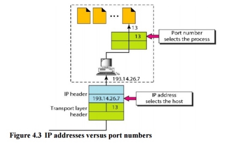
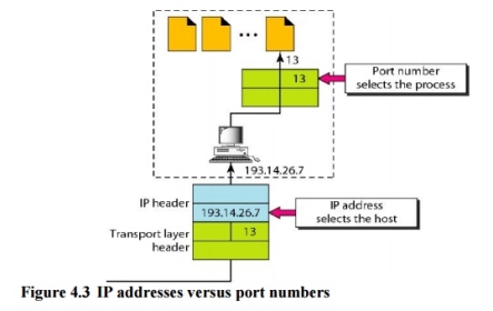
The IP addresses and port numbers play different roles in selecting the final destination of data. The destination IP address defines the host among the different hosts in the world. After the host has been selected, the port number defines one of the processes on this particular host (see Figure 4.3).
3. lANA Ranges The lANA (Internet Assigned Number Authority) has divided the port numbers into three ranges: well known, registered, and dynamic (or private), as shown in Figure 4.4. Well-known ports. The ports ranging from 0 to 1023 are assigned and controlledby lANA. These are the well-known ports. Registered ports. The ports ranging from 1024 to 49,151 are not assigned orcontrolled by lANA. They can only be registered with lANA to prevent duplication. Dynamic ports. The ports ranging from 49,152 to 65,535 are neither controllednor registered. They can be used by any process. These are the ephemeral ports.
Fig 3 – IANA ranges 4. Socket Addresses Process-to-process delivery needs two identifiers, IP address and the port number, at each end to make a connection. The combination of an IP address and a port number is called a socket address. The client socket address defines the client process uniquely just as the server socket address defines the server process uniquely (see Figure 4.5). UDP or TCP header contains the port numbers.
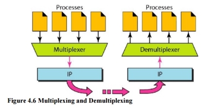
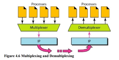
5. Multiplexing and Demultiplexing The addressing mechanism allows multiplexing and demultiplexing by the transport layer, as shown in Figure 4.6. Multiplexing At the sender site, there may be several processes that need to send packets. However, there is only one transport layer protocol at any time. This is a many-to-one relationship and requires multiplexing.
Demultiplexing At the receiver site, the relationship is one-to-many and requires demultiplexing. The transport layer receives datagrams from the network layer. After error checking and dropping of the header, the transport layer delivers each message to the appropriate process based on the port number.
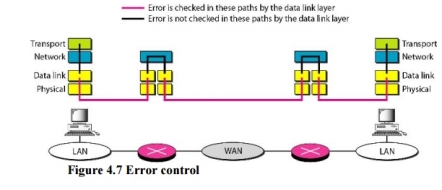
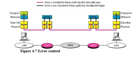
6. Connectionless Versus Connection-Oriented Service A transport layer protocol can either be connectionless or connection-oriented. Connectionless Service In a connectionless service, the packets are sent from one party to another with no need for connection establishment or connection release. The packets are not numbered; they may be delayed or lost or may arrive out of sequence. There is no acknowledgment either. Connection~Oriented Service In a connection-oriented service, a connection is first established between the sender and the receiver. Data are transferred. At the end, the connection is released. 7. Reliable Versus Unreliable The transport layer service can be reliable or unreliable. If the application layer program needs reliability, we use a reliable transport layer protocol by implementing flow and error control at the transport layer. This means a slower and more complex service. In the Internet, there are three common different transport layer protocols. UDP is connectionless and unreliable; TCP and SCTP are connection oriented and reliable. These three can respond to the demands of the application layer programs. The network layer in the Internet is unreliable (best-effort delivery), we need to implement reliability at the transport layer. To understand that error control at the data link layer does not guarantee error control at the transport layer, let us look at Figure 4.7.
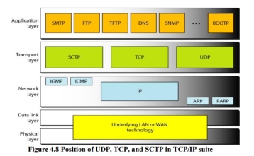
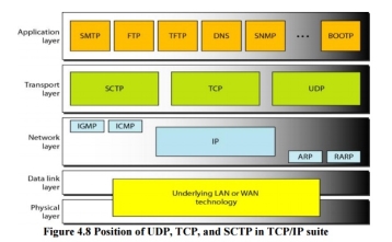
8. Three Protocols The original TCP/IP protocol suite specifies two protocols for the transport layer: UDP and TCP. We first focus on UDP, the simpler of the two, before discussing TCP. A new transport layer protocol, SCTP, has been designed. Figure 4.8 shows the position of these protocols in the TCP/IP protocol suite.
|
Key takeaways
- The data link layer is responsible for delivery of frames between two neighbouring nodes over a link. This is called node-to-node delivery. The network layer is responsible for delivery of datagrams between two hosts. This is called host-to-host delivery. Real communication takes place between two processes (application programs). We need process-to-process delivery. The transport layer is responsible for process-to-process delivery-the delivery of a packet, part of a message, from one process to another. Figure 4.1 shows these three types of deliveries and their domains
|
In computer networking, the UDP stands for User Datagram Protocol. The David P. Reed developed the UDP protocol in 1980. It is defined in RFC 768, and it is a part of the TCP/IP protocol, so it is a standard protocol over the internet. The UDP protocol allows the computer applications to send the messages in the form of datagrams from one machine to another machine over the Internet protocol (IP) network. The UDP is an alternative communication protocol to the TCP protocol (transmission control protocol). Like TCP, UDP provides a set of rules that governs how the data should be exchanged over the internet. The UDP works by encapsulating the data into the packet and providing its own header information to the packet. Then, this UDP packet is encapsulated to the IP packet and sent off to its destination. Both the TCP and UDP protocols send the data over the internet protocol network, so it is also known as TCP/IP and UDP/IP. There are many differences between these two protocols. UDP enables the process to process communication, whereas the TCP provides host to host communication. Since UDP sends the messages in the form of datagrams, it is considered the best-effort mode of communication. TCP sends the individual packets, so it is a reliable transport medium. Another difference is that the TCP is a connection-oriented protocol whereas, the UDP is a connectionless protocol as it does not require any virtual circuit to transfer the data. UDP also provides a different port number to distinguish different user requests and also provides the checksum capability to verify whether the complete data has arrived or not; the IP layer does not provide these two services. The following are the features of the UDP protocol:
UDP is the simplest transport layer communication protocol. It contains a minimum amount of communication mechanisms. It is considered an unreliable protocol, and it is based on best-effort delivery services. UDP provides no acknowledgment mechanism, which means that the receiver does not send the acknowledgment for the received packet, and the sender also does not wait for the acknowledgment for the packet that it has sent.
The UDP is a connectionless protocol as it does not create a virtual path to transfer the data. It does not use the virtual path, so packets are sent in different paths between the sender and the receiver, which leads to the loss of packets or received out of order. Ordered delivery of data is not guaranteed. In the case of UDP, the datagrams are sent in some order will be received in the same order is not guaranteed as the datagrams are not numbered.
The UDP protocol uses different port numbers so that the data can be sent to the correct destination. The port numbers are defined between 0 and 1023.
UDP enables faster transmission as it is a connectionless protocol, i.e., no virtual path is required to transfer the data. But there is a chance that the individual packet is lost, which affects the transmission quality. On the other hand, if the packet is lost in TCP connection, that packet will be resent, so it guarantees the delivery of the data packets.
The UDP does have any acknowledgment mechanism, i.e., there is no handshaking between the UDP sender and UDP receiver. If the message is sent in TCP, then the receiver acknowledges that I am ready, then the sender sends the data. In the case of TCP, the handshaking occurs between the sender and the receiver, whereas in UDP, there is no handshaking between the sender and the receiver.
Each UDP segment is handled individually of others as each segment takes different path to reach the destination. The UDP segments can be lost or delivered out of order to reach the destination as there is no connection setup between the sender and the receiver.
It is a stateless protocol that means that the sender does not get the acknowledgement for the packet which has been sent. Why do we require the UDP protocol? As we know that the UDP is an unreliable protocol, but we still require a UDP protocol in some cases. The UDP is deployed where the packets require a large amount of bandwidth along with the actual data. For example, in video streaming, acknowledging thousands of packets is troublesome and wastes a lot of bandwidth. In the case of video streaming, the loss of some packets couldn't create a problem, and it can also be ignored.
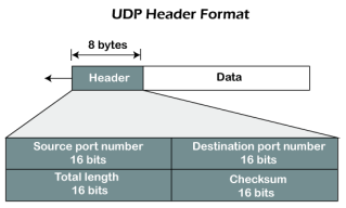
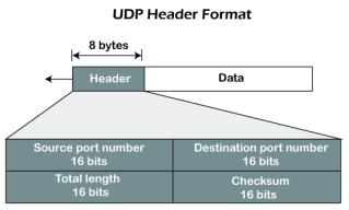
Fig 8 – UDP header format In UDP, the header size is 8 bytes, and the packet size is upto 65,535 bytes. But this packet size is not possible as the data needs to be encapsulated in the IP datagram, and an IP packet, the header size can be 20 bytes; therefore, the maximum of UDP would be 65,535 minus 20. The size of the data that the UDP packet can carry would be 65,535 minus 28 as 8 bytes for the header of the UDP packet and 20 bytes for IP header. The UDP header contains four fields:
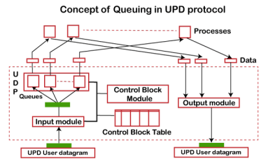
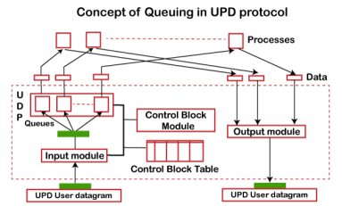
Concept of Queuing in UDP protocol
Fig 9 - Concept of Queuing in UDP protocol In UDP protocol, numbers are used to distinguish the different processes on a server and client. We know that UDP provides a process to process communication. The client generates the processes that need services while the server generates the processes that provide services. The queues are available for both the processes, i.e., two queues for each process. The first queue is the incoming queue that receives the messages, and the second one is the outgoing queue that sends the messages. The queue functions when the process is running. If the process is terminated then the queue will also get destroyed. UDP handles the sending and receiving of the UDP packets with the help of the following components:
Several processes want to use the services of UDP. The UDP multiplexes and demultiplexes the processes so that the multiple processes can run on a single host.
|
Key takeaways
- In computer networking, the UDP stands for User Datagram Protocol. The David P. Reed developed the UDP protocol in 1980. It is defined in RFC 768, and it is a part of the TCP/IP protocol, so it is a standard protocol over the internet. The UDP protocol allows the computer applications to send the messages in the form of datagrams from one machine to another machine over the Internet protocol (IP) network. The UDP is an alternative communication protocol to the TCP protocol (transmission control protocol). Like TCP, UDP provides a set of rules that governs how the data should be exchanged over the internet. The UDP works by encapsulating the data into the packet and providing its own header information to the packet. Then, this UDP packet is encapsulated to the IP packet and sent off to its destination. Both the TCP and UDP protocols send the data over the internet protocol network, so it is also known as TCP/IP and UDP/IP. There are many differences between these two protocols. UDP enables the process to process communication, whereas the TCP provides host to host communication. Since UDP sends the messages in the form of datagrams, it is considered the best-effort mode of communication. TCP sends the individual packets, so it is a reliable transport medium. Another difference is that the TCP is a connection-oriented protocol whereas, the UDP is a connectionless protocol as it does not require any virtual circuit to transfer the data.
- UDP also provides a different port number to distinguish different user requests and also provides the checksum capability to verify whether the complete data has arrived or not; the IP layer does not provide these two services.
TCP stands for Transmission Control Protocol. It is a transport layer protocol that facilitates the transmission of packets from source to destination. It is a connection-oriented protocol that means it establishes the connection prior to the communication that occurs between the computing devices in a network. This protocol is used with an IP protocol, so together, they are referred to as a TCP/IP. The main functionality of the TCP is to take the data from the application layer. Then it divides the data into a several packets, provides numbering to these packets, and finally transmits these packets to the destination. The TCP, on the other side, will reassemble the packets and transmits them to the application layer. As we know that TCP is a connection-oriented protocol, so the connection will remain established until the communication is not completed between the sender and the receiver. The following are the features of a TCP protocol:
TCP is a transport layer protocol as it is used in transmitting the data from the sender to the receiver.
TCP is a reliable protocol as it follows the flow and error control mechanism. It also supports the acknowledgment mechanism, which checks the state and sound arrival of the data. In the acknowledgment mechanism, the receiver sends either positive or negative acknowledgment to the sender so that the sender can get to know whether the data packet has been received or needs to resend.
This protocol ensures that the data reaches the intended receiver in the same order in which it is sent. It orders and numbers each segment so that the TCP layer on the destination side can reassemble them based on their ordering.
It is a connection-oriented service that means the data exchange occurs only after the connection establishment. When the data transfer is completed, then the connection will get terminated.
It is a full-duplex means that the data can transfer in both directions at the same time.
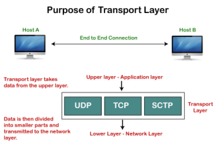
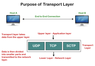
TCP is a stream-oriented protocol as it allows the sender to send the data in the form of a stream of bytes and also allows the receiver to accept the data in the form of a stream of bytes. TCP creates an environment in which both the sender and receiver are connected by an imaginary tube known as a virtual circuit. This virtual circuit carries the stream of bytes across the internet. Need of Transport Control Protocol In the layered architecture of a network model, the whole task is divided into smaller tasks. Each task is assigned to a particular layer that processes the task. In the TCP/IP model, five layers are application layer, transport layer, network layer, data link layer, and physical layer. The transport layer has a critical role in providing end-to-end communication to the directly application processes. It creates 65,000 ports so that the multiple applications can be accessed at the same time. It takes the data from the upper layer, and it divides the data into smaller packets and then transmits them to the network layer.
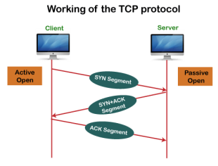
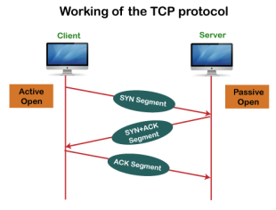
Fig 10 – Purpose of transport layer In TCP, the connection is established by using three-way handshaking. The client sends the segment with its sequence number. The server, in return, sends its segment with its own sequence number as well as the acknowledgement sequence, which is one more than the client sequence number. When the client receives the acknowledgment of its segment, then it sends the acknowledgment to the server. In this way, the connection is established between the client and the server.
Fig 11 – Working of the TCP protocol
It increases a large amount of overhead as each segment gets its own TCP header, so fragmentation by the router increases the overhead.
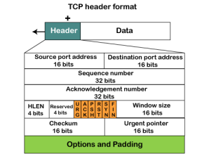
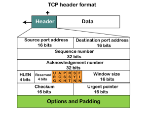
Fig 12 – TCP header format
It is a 16-bit field. It contains the size of data that the receiver can accept. This field is used for the flow control between the sender and receiver and also determines the amount of buffer allocated by the receiver for a segment. The value of this field is determined by the receiver.
It is a pointer that points to the urgent data byte if the URG flag is set to 1. It defines a value that will be added to the sequence number to get the sequence number of the last urgent byte.
The TCP port is a unique number assigned to different applications. For example, we have opened the email and games applications on our computer; through email application, we want to send the mail to the host, and through games application, we want to play the online games. In order to do all these tasks, different unique numbers are assigned to these applications. Each protocol and address have a port known as a port number. The TCP (Transmission control protocol) and UDP (User Datagram Protocol) protocols mainly use the port numbers. A port number is a unique identifier used with an IP address. A port is a 16-bit unsigned integer, and the total number of ports available in the TCP/IP model is 65,535 ports. Therefore, the range of port numbers is 0 to 65535. In the case of TCP, the zero-port number is reserved and cannot be used, whereas, in UDP, the zero port is not available. IANA (Internet Assigned Numbers Authority) is a standard body that assigns the port numbers.
Example of port number: 192.168.1.100: 7 In the above case, 192.168.1.100 is an IP address, and 7 is a port number. To access a particular service, the port number is used with an IP address. The range from 0 to 1023 port numbers are reserved for the standard protocols, and the other port numbers are user-defined. Why do we require port numbers? A single client can have multiple connections with the same server or multiple servers. The client may be running multiple applications at the same time. When the client tries to access some service, then the IP address is not sufficient to access the service. To access the service from a server, the port number is required. So, the transport layer plays a major role in providing multiple communication between these applications by assigning a port number to the applications. Classification of port numbers The port numbers are divided into three categories:
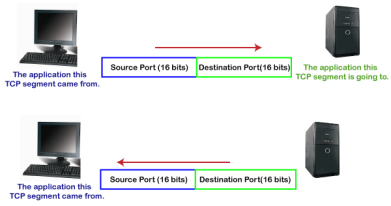
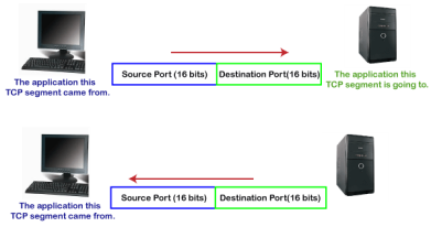
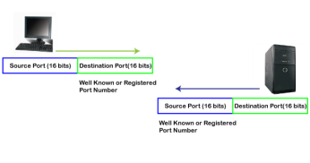
The range of well-known port is 0 to 1023. The well-known ports are used with those protocols that serve common applications and services such as HTTP (Hypertext transfer protocol), IMAP (Internet Message Access Protocol), SMTP (Simple Mail Transfer Protocol), etc. For example, we want to visit some websites on an internet; then, we use http protocol; the http is available with a port number 80, which means that when we use http protocol with an application then it gets port number 80. It is defined that whenever http protocol is used, then port number 80 will be used. Similarly, with other protocols such as SMTP, IMAP; well-known ports are defined. The remaining port numbers are used for random applications. The range of registered port is 1024 to 49151. The registered ports are used for the user processes. These processes are individual applications rather than the common applications that have a well-known port. The range of dynamic port is 49152 to 65535. Another name of the dynamic port is ephemeral ports. These port numbers are assigned to the client application dynamically when a client creates a connection. The dynamic port is identified when the client initiates the connection, whereas the client knows the well-known port prior to the connection. This port is not known to the client when the client connects to the service. As we know that both TCP and UDP contain source and destination port numbers, and these port numbers are used to identify the application or a server both at the source and the destination side. Both TCP and UDP use port numbers to pass the information to the upper layers. Let's understand this scenario. Suppose a client is accessing a web page. The TCP header contains both the source and destination port.
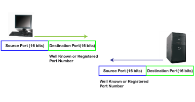
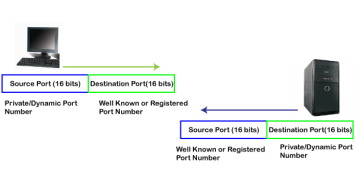
In the above diagram, Source Port: The source port defines an application to which the TCP segment belongs to, and this port number is dynamically assigned by the client. This is basically a process to which the port number is assigned. Destination port: The destination port identifies the location of the service on the server so that the server can serve the request of the client. In the above diagram, Source port: It defines the application from where the TCP segment came from. Destination port: It defines the application to which the TCP segment is going to. In the above case, two processes are used: Encapsulation: Port numbers are used by the sender to tell the receiver which application it should use for the data. Decapsulation: Port numbers are used by the receiver to identify which application should it sends the data to. Let's understand the above example by using all three ports, i.e., well-known port, registered port, and dynamic port. First, we look at a well-known port.
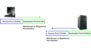
The well-known ports are the ports that serve the common services and applications like http, ftp, smtp, etc. Here, the client uses a well-known port as a destination port while the server uses a well-known port as a source port. For example, the client sends an http request, then, in this case, the destination port would be 80, whereas the http server is serving the request so its source port number would be 80. Now, we look at the registered port.
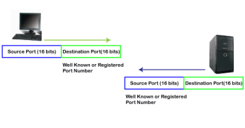
The registered port is assigned to the non-common applications. Lots of vendor applications use this port. Like the well-known port, client uses this port as a destination port whereas the server uses this port as a source port. At the end, we see how dynamic port works in this scenario.
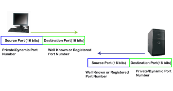
The dynamic port is the port that is dynamically assigned to the client application when initiating a connection. In this case, the client uses a dynamic port as a source port, whereas the server uses a dynamic port as a destination port. For example, the client sends an http request; then in this case, destination port would be 80 as it is a http request, and the source port will only be assigned by the client. When the server serves the request, then the source port would be 80 as it is an http server, and the destination port would be the same as the source port of the client. The registered port can also be used in place of a dynamic port.
Let's look at the below example. Suppose client is communicating with a server, and sending the http request. So, the client sends the TCP segment to the well-known port, i.e., 80 of the HTTP protocols. In this case, the destination port would be 80 and suppose the source port assigned dynamically by the client is 1028. When the server responds, the destination port is 1028 as the source port defined by the client is 1028, and the source port at the server end would be 80 as the HTTP server is responding to the request of the client. |
Key takeaways
- TCP stands for Transmission Control Protocol. It is a transport layer protocol that facilitates the transmission of packets from source to destination. It is a connection-oriented protocol that means it establishes the connection prior to the communication that occurs between the computing devices in a network. This protocol is used with an IP protocol, so together, they are referred to as a TCP/IP.
- The main functionality of the TCP is to take the data from the application layer. Then it divides the data into a several packets, provides numbering to these packets, and finally transmits these packets to the destination. The TCP, on the other side, will reassemble the packets and transmits them to the application layer. As we know that TCP is a connection-oriented protocol, so the connection will remain established until the communication is not completed between the sender and the receiver.
What is congestion? A state occurring in network layer when the message traffic is so heavy that it slows down network response time. Effects of Congestion
Congestion control algorithms
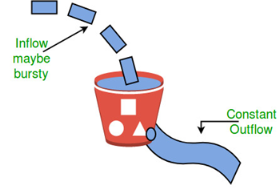
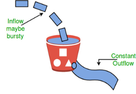
Let us consider an example to understand Imagine a bucket with a small hole in the bottom.No matter at what rate water enters the bucket, the outflow is at constant rate.When the bucket is full with water additional water entering spills over the sides and is lost.
Fig 13 – Leaky bucket algorithm
Similarly, each network interface contains a leaky bucket and the following steps are involved in leaky bucket algorithm:
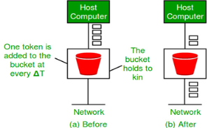
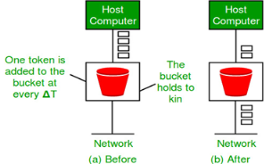
Need of token bucket Algorithm:- The leaky bucket algorithm enforces output pattern at the average rate, no matter how bursty the traffic is. So in order to deal with the bursty traffic we need a flexible algorithm so that the data is not lost. One such algorithm is token bucket algorithm. Steps of this algorithm can be described as follows:
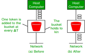
Let’s understand with an example, In figure (A) we see a bucket holding three tokens, with five packets waiting to be transmitted. For a packet to be transmitted, it must capture and destroy one token. In figure (B) We see that three of the five packets have gotten through, but the other two are stuck waiting for more tokens to be generated. Ways in which token bucket is superior to leaky bucket: The leaky bucket algorithm controls the rate at which the packets are introduced in the network, but it is very conservative in nature. Some flexibility is introduced in the token bucket algorithm. In the token bucket, algorithm tokens are generated at each tick (up to a certain limit). For an incoming packet to be transmitted, it must capture a token and the transmission takes place at the same rate. Hence some of the busty packets are transmitted at the same rate if tokens are available and thus introduces some amount of flexibility in the system. Formula: M * s = C + ρ * s where S – is time taken M – Maximum output rate ρ – Token arrival rate C – Capacity of the token bucket in byte Let’s understand with an example,
Stream Control Transmission Protocol (SCTP) is a reliable transport protocol that runs on top of a packet service without potentially unreliable connection such as IP. It was developed specifically for applications and signaling offers recognized without unduplicated transfer error datagrams (messages). Detection of data corruption, data loss and data duplication is performed using checksums and sequence numbers. A selective retransmission mechanism is applied to correct the loss or corruption of data. The decisive difference is TCP multi-homing and the concept of multiple streams in a connection. Where in a TCP flow is called a sequence of bytes, a SCTP stream represents a sequence of messages. SCTP tries to combine the advantages of UDP and TCP, but avoid their drawbacks; it is defined in IETF RFC 4960. SCTP is used on several network internal control plane interfaces, with these SCTP applications −
Two categories of procedures across S1-MME exist: UE associated and non-associated UE. Furthermore two classes of messages are defined: Class1 is with the class 2 is answered. Class 1 and related procedures initiator/response messages are listed in the table below; procedures for Class 2 message names are largely identical to the procedure names, and the table below (second table) lists only these.
X2 application protocol has much in common with the S1-AP; same categorization in class 1 and class 2 messages is made. The setup message is much smaller, corresponding to the specialized function of X2.
|
Key takeaway
- Stream Control Transmission Protocol (SCTP) is a reliable transport protocol that runs on top of a packet service without potentially unreliable connection such as IP. It was developed specifically for applications and signaling offers recognized without unduplicated transfer error datagrams (messages). Detection of data corruption, data loss and data duplication is performed using checksums and sequence numbers.
- A selective retransmission mechanism is applied to correct the loss or corruption of data. The decisive difference is TCP multi-homing and the concept of multiple streams in a connection. Where in a TCP flow is called a sequence of bytes, a SCTP stream represents a sequence of messages. SCTP tries to combine the advantages of UDP and TCP, but avoid their drawbacks; it is defined in IETF RFC 4960.
- SCTP is used on several network internal control plane interfaces, with these SCTP applications –
- S1-MME: between eNodeB and MME
- SBc: between MME and SBc.
- S6a: between MME and HSS
- S6d: between SGSN and HSS
- SGs: between MSC/VLR and MME
- S13: between MME and EIR
QoS is an overall performance measure of the computer network. If a packet gets lost or acknowledgement is not received (at sender), the re-transmission of data will be needed. This decreases the reliability. E- mail and file transfer need to have a reliable transmission as compared to that of an audio conferencing. 2. Delay Delay of a message from source to destination is a very important characteristic. However, delay can be tolerated differently by the different applications. The time delay cannot be tolerated in audio conferencing (needs a minimum time delay), while the time delay in the e-mail or file transfer has less importance. The jitter is the variation in the packet delay. Different applications need the different bandwidth. Video conferencing needs more bandwidth in comparison to that of sending an e-mail. Integrated Services and Differentiated Service These two models are designed to provide Quality of Service (QoS) in the network. 1. Integrated Services (IntServ) Integrated service is flow-based QoS model and designed for IP. An IP is connectionless, datagram, packet-switching protocol. To implement a flow-based model, a signaling protocol is used to run over IP, which provides the signaling mechanism to make reservation (every applications need assurance to make reservation), this protocol is called as RSVP. While making reservation, resource needs to define the flow specification. The flow specification has two parts: It defines the resources that the flow needs to reserve. For example: Buffer, bandwidth, etc. It defines the traffic categorization of the flow. After receiving the flow specification from an application, the router decides to admit or deny the service and the decision can be taken based on the previous commitments of the router and current availability of the resource. The two classes of services to define Integrated Services are: This service guarantees that the packets arrive within a specific delivery time and not discarded, if the traffic flow maintains the traffic specification boundary. For example: Audio conferencing.
This type of service is designed for the applications, which can accept some delays, but are sensitive to overload network and to the possibility to lose packets. Problems with Integrated Services
The two problems with the Integrated services are: i) Scalability In Integrated Services, it is necessary for each router to keep information of each flow. But, this is not always possible due to growing network. The integrated services model provides only two types of services, guaranteed and control-load. 2. Differentiated Services (DS or Diffserv):
The solutions to handle the problems of Integrated Services are explained below: The main processing unit can be moved from central place to the edge of the network to achieve the scalability. The router does not need to store the information about the flows and the applications (or the hosts) define the type of services they want every time while sending the packets. The routers, route the packets on the basis of class of services define in the packet and not by the flow. This method is applied by defining the classes based on the requirement of the applications. What is congestion?
A state occurring in network layer when the message traffic is so heavy that it slows down network response time. Effects of Congestion
Congestion control algorithms
Let us consider an example to understand Imagine a bucket with a small hole in the bottom.No matter at what rate water enters the bucket, the outflow is at constant rate.When the bucket is full with water additional water entering spills over the sides and is lost.
Fig 14 – Leaky bucket algorithm
Similarly, each network interface contains a leaky bucket and the following steps are involved in leaky bucket algorithm:
Need of token bucket Algorithm:- The leaky bucket algorithm enforces output pattern at the average rate, no matter how bursty the traffic is. So in order to deal with the bursty traffic we need a flexible algorithm so that the data is not lost. One such algorithm is token bucket algorithm. Steps of this algorithm can be described as follows:
Let’s understand with an example, In figure (A) we see a bucket holding three tokens, with five packets waiting to be transmitted. For a packet to be transmitted, it must capture and destroy one token. In figure (B) We see that three of the five packets have gotten through, but the other two are stuck waiting for more tokens to be generated.
Ways in which token bucket is superior to leaky bucket: The leaky bucket algorithm controls the rate at which the packets are introduced in the network, but it is very conservative in nature. Some flexibility is introduced in the token bucket algorithm. In the token bucket, algorithm tokens are generated at each tick (up to a certain limit). For an incoming packet to be transmitted, it must capture a token and the transmission takes place at the same rate. Hence some of the busty packets are transmitted at the same rate if tokens are available and thus introduces some amount of flexibility in the system. Formula: M * s = C + ρ * s Let’s understand with an example,
|
Key takeaways
QoS is an overall performance measure of the computer network.
Important flow characteristics of the QoS are given below:
1. Reliability
If a packet gets lost or acknowledgement is not received (at sender), the re-transmission of data will be needed. This decreases the reliability.
The importance of the reliability can differ according to the application.
For example:
E- mail and file transfer need to have a reliable transmission as compared to that of an audio conferencing.
2. Delay
Delay of a message from source to destination is a very important characteristic. However, delay can be tolerated differently by the different applications.
For example:
The time delay cannot be tolerated in audio conferencing (needs a minimum time delay), while the time delay in the e-mail or file transfer has less importance.
3. Jitter
The jitter is the variation in the packet delay.
If the difference between delays is large, then it is called as high jitter. On the contrary, if the difference between delays is small, it is known as low jitter.
Example:
Case1: If 3 packets are sent at times 0, 1, 2 and received at 10, 11, 12. Here, the delay is same for all packets and it is acceptable for the telephonic conversation.
Case2: If 3 packets 0, 1, 2 are sent and received at 31, 34, 39, so the delay is different for all packets. In this case, the time delay is not acceptable for the telephonic conversation.
4. Bandwidth
Different applications need the different bandwidth.
For example:
Video conferencing needs more bandwidth in comparison to that of sending an e-mail.
References
1. Computer Networks, 8th Edition, Andrew S. Tanenbaum, Pearson New International Edition.
2. Internetworking with TCP/IP, Volume 1, 6th Edition Douglas Comer, Prentice Hall of India.
3. TCP/IP Illustrated, Volume 1, W. Richard Stevens, Addison-Wesley, United States of America.
