Module 5
Communication System
Microwave means very short wave. The microwave frequency spectrum is 1GHz to 30GHz. Lower frequency bands are congested and demand for point to point communication continue to increase.
For long distance communication microwave signals are used. It is the communication link which make the communication easily possible. The fig given below shows the basic block diagram of microwave communication system,
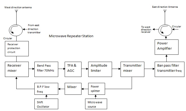
Fig. Block diagram of Microwave link repeater station
Antenna- Parabolic refractor type of antenna is used here which helps to transmit and receive the signal.
Circulator: A circulator helps to isolate transmitter with the receiver input and to couple transmitter to antenna and antenna to receiver input.
Protection Circuitry: For the safety of the mixer from the overloads protection circuitry is used.
Mixer (Receiver): It has two outputs. In which one output is the incoming signal and other output is the signal from lower band pass filter (BPF). The mixer gives the output an IF signal of 70Mhz.
Band pass filter (BPF): It provides the necessary selectivity to the receiver and it prevents the interference.
IF amplifier and AGC- It amplifies the signal up to a intermediate frequency of 70Mhz. And AGC (automatic gain control) controls the gain.
Amplitude limiter: Amplitude limiter avoids unwanted distortion or variation in amplitude as the signal is frequency modulated.
Mixer (Transmitter): It is used to convert IF frequency to transmitting microwave frequency band to pass through it and hence prevent interference.
Power Amplifier: This amplifier amplifies the transmitted power from a repeater section in the range of 0.2W to 10W.
Microwave Source: Klystron & Gunn Oscillators were used as microwave source. Now, V H F transistor crystal oscillators are used for microwave source.
Power Splitter: It divides the output power from a microwave source and feeds a large portion to the transmitter mixer, which converts it into transmitting microwave frequency.
Shift Oscillator Shift: It provides one of the inputs to the balanced mixer so that it produces 70MHz IF at the output of receiver mixer.
The one carrier can transmit the signals over 600 to 2700 channels of microwave link. Therefore the number of carriers in each direction can be four to twelve.
Microwave Transmitter
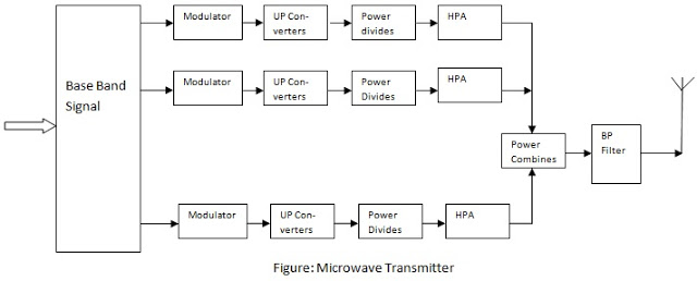
The fig given below shows the block diagram of a microwave transmitter station on earth.
 |
|
The uplink frequency is used to transmit the signal. After encoding and modulation of signal the converter multiply the signal frequency and uplink frequency. That multiplied frequency signal is applied to power dividers. The output of power divider gives to the high power amplifier as input. Generally travelling wave tube amplifiers or multicavity klystron amplifiers are used as power amplifier.
Here the modulation and encoding is performed at 70 MHz intermediate frequency and is then upconverted to a uplink frequency of 6 GHz. Power combining amplifier combines all the output which are given by several high power amplifiers and this combined output then passes through BPF and circulators. Frequency stability and power control are necessary to remove interferences. The manufacturing is high and it increases as transmitted power increases.
Microwave Receiver
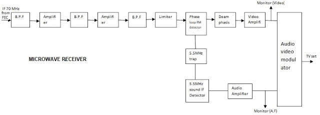 |
Fig. Block Diagram of Microwave Receiver |
At the receiver station the first stage of the terminal is the front end converter which is generally a double converter. This convertor is used to convert the down link frequency signal of the order of GHz into an intermediate frequency (IF) of 70 MHz.
Now this 70MHz IF signal is first passed through a chain of BPFs and amplifier combinations to improve signal strength. Therefore this IF signal is demodulated to get the original message signal. A phase-locked loop (PLL) type of FM demodulator is used here.
Now the amplified signal is given to de-emphasis network. A 5.5 MHz sound trap is provided in the circuit to get the sound IF. Now this sound IF is transfered to FM detector to get the original audio signal.
Advantages and disadvantages of Microwave communication
Advantages
- Cost is low.
- Installation is easier and faster.
- Irregular ground difficulties are overcome
- Repeater specing may be increased by increasing tower height.
Disadvantages
- Restriction to line of sight operation on conventional link
- It is difficult to provide short distance branch circuits to intermediate exchanges or subscribers.
- Adverse weather conditions can cause severe fading and beam bending.
- The high level of linearity required in the repeater poses a severe design problem.
Applications of Microwave Communication
- Most commonly used in satellite communications, radar signals, phones, and navigational applications.
- Other applications where the microwaves used are medical treatments, drying materials, and in households for the preparation of food.
Microwave Bands:
Microwaves are found at the higher end of the radio frequency spectrum, but they are generally different from radio waves based on the technology using them. Microwaves are divided into sub-bands depending on their wavelengths which are giving different information. The frequency bands of microwaves are as follows:
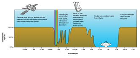
Microwave Bands
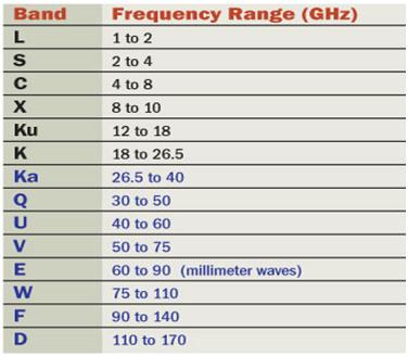
Microwave frequency bands and their frequency range
L-Band:
- The frequency range : 1 GHz to 2 GHz
- Wavelength Range: 15cm to 30cm.
- Application: 1) These frequency ranges of waves are used in navigations. 2)GSM mobile phones, 3) In military applications. 4)They can be used to measure the soil moisture of rain forests.
S-Band:
- The frequency range: 2 GHz to 4 GHz.
- Wavelength range: 7.5cm to 15 cm.
- Application: 1) These frequency ranges of waves can be used in navigation 2) In beacons 3) optical communications, and wireless networks.
C-Band:
- The frequency range: 4 GHz to 8 GHz.
- Wavelength range: 3.75 cm to 7.5 cm
- C band microwaves go through clods, dust, smoke, snow, and rain to reveal the earth’s surface.
- Application: 1) These microwaves can be used in long-distance radio telecommunications.
X-Band:
The frequency range: 8 GHz to 12 GHz.
Wavelength range: 25 mm to 37.5 mm.
Application: 1) These waves are used in satellite communications, 2)broadband communications, 3)radars, space communications, and amateur radio signals.
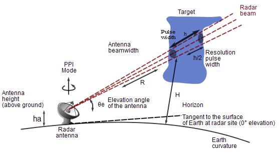
Radar applications using microwaves
Ku-Band:
- The frequency range: 12 GHz to 18 GHz
- Wavelength range: 16.7 mm to 25 mm.
- “Ku” is Quartz-under.
- Application: 1) Used in satellite communications for measuring the changes in the energy of the microwave pulses 2) Used to determine the speed and direction of wind near coastal areas.
K-Band and Ka-Band:
- The frequency range of K-Band: 18 GHz to 26.5 GHz and Frequency range of Ka-band: 26.5 GHz to 40 GHz.
- Wavelength range of K-band: 11.3 mm to 16.7 mm. And Wavelength range of Ka-band: 5 mm to 11.3 mm.
- Application: 1) Used in satellite communications, 2) Astronomical observations, and radars.
- Radars in this frequency range gives short-range, high resolution, and high amounts of data at the renewing rate.
V-Band:
- This band stays for high attenuation.
- The frequency range: 50 GHz to 75 GHz.
- The wavelength range: 4.0 mm to 6.0 mm.
- Application: 1) Used in radar application.
- There are some more bands like U, E, W, F, D, and P having very high frequencies which are used in several applications.
An optical fiber may be understood as a dielectric waveguide, that operates at optical frequencies. The device or a tube, if bent or if terminated to radiate energy, is termed a waveguide, in general. Following image shows a bunch of fiber optic cables.
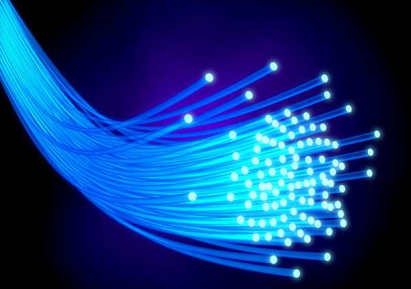
The electromagnetic energy travels through fiber optic cable in the form of light. The light propagation, with a waveguide can be represented in terms of a set of guided electromagnetic waves, termed as modes of the waveguide.
Working Principle
A basic optical parameter should have an idea about, while studying fiber optics is Refractive index. According to definition, “The ratio of the speed of light in a vacuum to that in matter is the index of refraction n of the material.” It is given as −
n = c/v
Where,
c = the speed of light in free space = 3 × 10⁸ m/s
v = the speed of light in di-electric or non-conducting material
Generally, when n2 < n1 reflection takes place for a travelling light ray. The bent of light ray at the interface is the result of difference in the speed of light in two materials that have different refractive indices. The relationship between these angles at the interface can be termed as Snell’s law. It is represented as −

Where,
Θ1 = Incident angel
Θ2 = Refracted angle
n1 and n2 are the refractive indices of two materials
For an optically dense material, if the reflection takes place within the same material, then such a phenomenon is called as internal reflection. The incident angle and refracted angle are shown in the following figure.
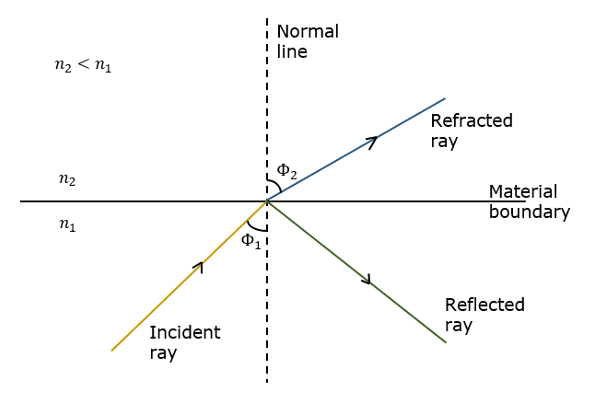
If the angle of incidence Θ1 is much larger, then the refracted angle Θ2 at a point becomes Π/2. Further refraction is not possible beyond this point. Hence, such a point is called as Critical angle Θc. When the incident angle Θ1 is greater than the critical angle, the condition for total internal reflection is satisfied.
The following figure shows these terms clearly.
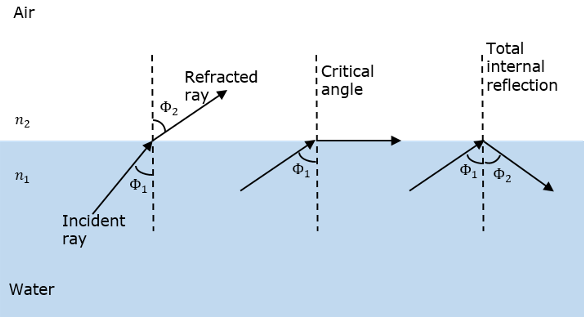
A light ray, if passed into a glass, at such condition, it is totally reflected back into the glass with no light escaping from the surface of the glass.
Parts of a Fiber
The most commonly used optical fiber is single solid di-electric cylinder of radius a and index of refraction n1. The following figure explains the parts of an optical fiber.
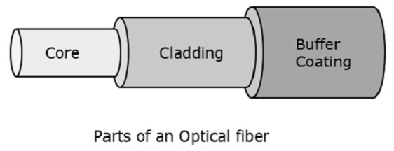
This cylinder is known as the Core of the fiber. A solid di-electric material surrounds the core, which is called as Cladding. Cladding has a refractive index n2 which is less than n1.
Cladding helps in −
- Reducing scattering losses.
- Adds mechanical strength to the fiber.
- Protects the core from absorbing unwanted surface contaminants.
Types of Optical Fibers
Depending upon the material composition of the core, there are two types of fibers used commonly. They are −
- Step-index fiber − The refractive index of the core is uniform throughout and undergoes an abrupt change (or step) at the cladding boundary.
- Graded-index fiber − The core refractive index is made to vary as a function of the radial distance from the center of the fiber.
Both of these are further divided into −
- Single-mode fiber − These are excited with laser.
- Multi-mode fiber − These are excited with LED.
Optical Fiber Communications
The fig given below shows the Basic block diagram of optical fiber communication system, which is made up of following important blocks.
1. Transmitter
2. Information channel
3. Receiver.
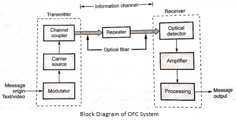
Message origin
Generally message origin is a form of transducer. This transducer converts a non-electrical message i.e. text/video into an electrical signal.
e.g. Microphones which converts sound waves into currents and TV which converts images into current.
Modulator
The modulator performs two main functions.
- It converts the electrical message into the proper format.
- It impresses this signal onto the wave generated by the carrier source.
Two distinct categories of modulation are used i.e. analog modulation and digital modulation.
Carrier source
The given information is transmitted with the help of carrier source generates. This waves are nothing but the carrier. For fiber optic system, a laser diode (LD) or a light emitting diode (LED) is used. They can be known as optic oscillators. Optic oscillators provide stable, single frequency waves with sufficient power for long distance propagation.
Channel coupler
The coupler feeds power into the information channel. For an atmospheric optical system, the channel coupler is a lens used to collimate the light emitted by the source and direct this light towards the receiver. The coupler must efficiently transfer the modulated light beam from the source to the optical fiber. The design of the channel coupler is an important part of the fiber system due to the possibility of large losses
Information channel
The information channel is the route between the transmitter and the receiver. In fiber optic communications, the channel is a fiberglass or plastic. Desirable characteristics of the information channel include low attenuation and wide cone angle of light acceptance. Optical amplifiers increase the power levels of weak signals. Amplifiers are needed in very long links to provide sufficient power to the receiver. The repeaters can be used only for digital systems. They convert the weak and distorted optical signals into electrical and then regenerate the original pulse trains for greater transmission.
Another important property of the information channel is the propagation time of the poles traveling along it. A signal that propagates along a fiber normally contains a range of optical frequencies and divides its power along several ray trajectories. This results in a distortion of the propagation signal. In a digital system, this distortion appears as an extension and deformation of the pulses. The dispersion is so large that the adjacent pulses begin to overlap and become unrecognizable as separate bits of information
Optical Detector
The information that is transmitted is detector. In the fiber system, the optical wave is converted into an electric current by means of a photodetector. The current developed by the detector is proportional to the power in the incident optical wave. The output current of the detector contains the information transmitted. This detector output is filtered to eliminate constant polarization and then amplify. The important properties of photodetectors are their small size, economy, long service life, low power consumption, high sensitivity to optical signals and rapid response to rapid variations in theoretical power.
Signal Processing
Signal processing includes the processes of filtering, amplification. Proper filtering removes the unwanted signals and maximizes the ratio of signal to unwanted power. The decision circuit is an additional block in digital system. The BER should be very small for quality communications.
Message output
The electrical form of the message emerging from the signal processor are converted into original form i.e. into a sound wave or visual image. If computers or other machines are connected through a fiber system, these signals are directly usable.
Functional Advantages
The functional advantages of optical fibers are −
- The transmission bandwidth of the fiber optic cables is higher than the metal cables.
- The amount of data transmission is higher in fiber optic cables.
- The power loss is very low and hence helpful in long-distance transmissions.
- Fiber optic cables provide high security and cannot be tapped.
- Fiber optic cables are the most secure way for data transmission.
- Fiber optic cables are immune to electromagnetic interference.
- These are not affected by electrical noise.
Physical Advantages
The physical advantages of fiber optic cables are −
- The capacity of these cables is much higher than copper wire cables.
- Though the capacity is higher, the size of the cable doesn’t increase like it does in copper wire cabling system.
- The space occupied by these cables is much less.
- The weight of these FOC cables is much lighter than the copper ones.
- Since these cables are di-electric, no spark hazards are present.
- These cables are more corrosion resistant than copper cables, as they are bent easily and are flexible.
- The raw material for the manufacture of fiber optic cables is glass, which is cheaper than copper.
- Fiber optic cables last longer than copper cables.
Disadvantages
Although fiber optics offer many advantages, they have the following drawbacks −
- Though fiber optic cables last longer, the installation cost is high.
- The number of repeaters are to be increased with distance.
- They are fragile if not enclosed in a plastic sheath. Hence, more protection is needed than copper ones.
Applications of Fiber Optics
The optical fibers have many applications. Some of them are as follows −
- Used in telephone systems
- Used in sub-marine cable networks
- Used in data link for computer networks, CATV Systems
- Used in CCTV surveillance cameras
- Used for connecting fire, police, and other emergency services.
- Used in hospitals, schools, and traffic management systems.
- They have many industrial uses and also used for in heavy duty constructions.
In general terms, a smaller object that revolves around a larger object in space is a satellite. For example, moon is a natural satellite of earth.
We know that sharing of information between two or more entities is Communication. This communication can be done through any medium or channel. Simply we can say that sending, receiving and processing of information is communication.
When this exchanging of information takes place between two earth station through satellite is known as Satellite Communication. In this communication, the carrier signals are electromagnetic waves. These signals carry the information like voice, audio, video or any other data between ground and space and vice-versa.
Sputnik 1 is the world’s Ist artificial satellite which is launched 1957 by Soviet Union. After 18 years India launched India’s Ist artificial satellite named, Aryabhata in 1975.
Need of Satellite Communication
Earlier two kinds of propagations are used for long distance communication.
- Ground wave propagation − It is suitable for frequencies up to 30MHz. The troposphere conditions of the earth is used for this type of communication.
- Sky wave propagation – It is suitable for frequencies between 30–40 MHz. The ionosphere properties of the earth is used here.
In both kind of wave propagation, the maximum hop or the station distance is limited to 1500KM only. To overcome this limitation Satellite communication is used. In this method, satellites provide communication for long distances, which is well beyond the line of sight.
Since the satellites locate at certain height above earth, the communication takes place between any 2 earth stations easily via satellite. So, it overcomes the limitation of communication between 2 earth stations due to earth’s curvature.
How a Satellite Works
A satellite is nothing but a body which moves around another body in a definite path. A microwave repeater station in space is also communication satellite. Satellite communication technique used in telecommunications, radio and television along with internet applications.
The circuit used to increase the strength of the received signal is a repeater and then transmit it. But, this repeater also works as a transponder. That means, it changes the frequency band of the transmitted signal from the received one.
The frequency with which, the signal is sent into the space is nothing but Uplink frequency. Similarly, the frequency with which, the signal is sent by the transponder is nothing but Downlink frequency. The figure given below shows the concept of Uplink and Downlink frequencies,
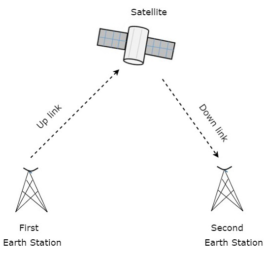
Fig. The most basic satellite link provides point-to-point connectivity
The transmission of signal from one(first) earth station to satellite through a channel is called as uplink. Similarly, the transmission of signal from satellite to another(second) earth station through a channel is called as downlink.
Uplink frequency is the frequency at which, the first earth station is communicating with satellite. The satellite transponder converts this signal into another frequency and sends it down to the second earth station. This frequency is called as Downlink frequency. Similarly this action can done vice-versa i.e. second earth station can also communicate with the first one.
The process of satellite communication begins at an earth station. Here, an installation is designed to transmit and receive signals from a satellite in an orbit around the earth. Earth stations send the information to satellites in the form of high powered, high frequency (GHz range) signals.
The satellites receive and retransmit the signals back to earth where they are received by other earth stations in the coverage area of the satellite. Satellite's footprint is the area which receives a signal of useful strength from the satellite.
Block diagram of Satellite communication
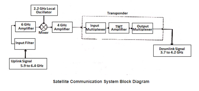
The uplink frequencies (5.9 – 6.4GHz) are used for transmission of signal from one earth station to satellite. The downlink frequencies (3.7 – 4.2GHz) are used for receiving the signal from satellite to other earth station.
Here the mixer and local oscillator coverts the uplink frequencies into lower frequencies. The com satellite acts as a repeater station, it receives the signal, amplifier amplifies the signal and then transmit over the next frequencies to avoid the interference between uplink and downlink.
With the help of transponder we can established two way communication. A satellite with two transponder can support a signal T.V. Channel or 240 telephone lines. A satellite with 48 transponder can accommodate 4000 T.P. Ckts and 2 T.V. Channels. Now a days satellite is using digital tech, because of this 1 satellite can handle 1, 20, 000 T.P. Channels and more that 500 T.V. Channels.
Satellite Communication Earth Station
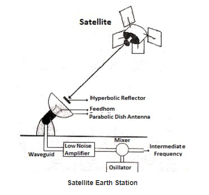
The fig above shows the equipment used in satellite earth station. Earth station made up of a dish antenna transmitter the high frequencies microwave signals (5.9-6.4GHz). Some earth stations are also known as ground station, which can transmit and receive the signals while other can only receive signals.
As it is long distance communication so there may be loss of signal, so to avoid the loss a high di9rective and a high gain antenna is necessary at the earth station. The power required for the signal while reaching back from satellite to earth is very small, so a parabolic dish antenna with 61m diameter, at receiver end, provides a high gain and amplify the signal power.
Earth Orbit Satellite
The position of the satellite should be proper in corresponding earth orbit after leaving it in the space. That satellite revolves in that same orbit to satisfy its purpose for military, scientific or commercial. The Earth Orbits are the orbits which are assigned to satellite with respect to earth.
Based on the requirement of the satellite we have to choose the proper orbit.
E.g. Suppose satellite is placed in lower orbit, it takes less time to complete the revolution and resolution is better in an onboard camera. Similarly, if satellite is placed in higher orbit then it requires more time to complete the revolution but it covers more area or surface of the earth at a time.
The three important types of Earth Orbit satellites are as given below −
- Geosynchronous Earth Orbit Satellites
- Medium Earth Orbit Satellites
- Low Earth Orbit Satellites
Geosynchronous Earth Orbit Satellites
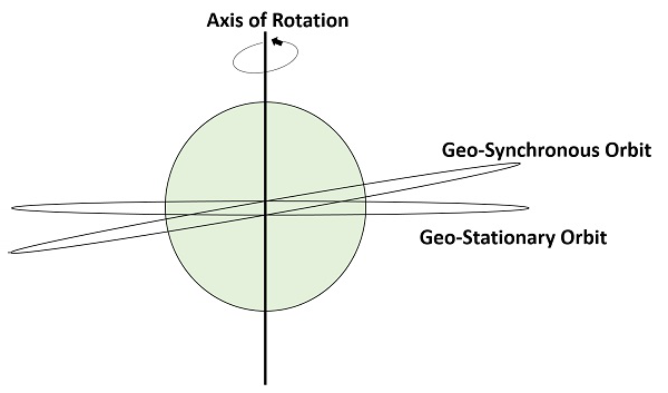
The orbit which is placed at distance of 22,300 miles above the earth orbit is known as a Geo-synchronous Earth Orbit (GEO). This orbit shows the synchronization with real day i.e. 23 hours 56 minutes. This orbit can have inclination and eccentricity.
This orbit is not circular. This orbit is tilted at the poles of the earth. But, it appears stationary when observed from the Earth. These satellites are used for satellite Television.
The same geo-synchronous orbit, if it is circular and in the plane of equator, then it is called as Geostationary orbit. These Satellites are placed at 35,900kms (same as Geosynchronous) above the Earth’s Equator and they keep on rotating with respect to earth’s direction (west to east).
The advantage of Geostationary orbit is that no need to track the antennas in order to find the position of satellites.
Applications of Geostationary Earth Orbit Satellites
1) Weather forecasting.
2) Satellite TV.
3) Satellite radio and other types of global communications.
The figure given below shows the difference between Geo-synchronous and Geo-stationary orbits. The axis of rotation indicates the movement of Earth.
Medium Earth Orbit Satellites
Medium Earth Orbit (MEO) satellites will orbit placed at distances of about 8000 miles from earth's surface. Signals transmitted through this orbit travel a shorter distance. Due to this, the signal strength gets improved at the receiving end.
If the transmission delay is shorter the communication system will be better. So it is useful for real-time communications, For e.g., if a GEO satellite requires 0.25 seconds for a round trip, then MEO satellite requires less than 0.1 seconds to complete the same trip. MEOs operate in the frequency range of 2 GHz and above.
Application:
1) Used for High speed telephone signals.
Low Earth Orbit Satellites mainly
Low Earth Orbit (LEO) satellites can be classified into three categories. That are 1) little LEOs, 2) big LEOs, and 3) Mega-LEOs. LEOs will orbit placed at a distance of 500 to 1000 miles above the earth's surface. For satellite phones and GPS, these orbital satellites are used.
It reduces transmission delay to only 0.05 seconds. Little LEOs will operate in the 800 MHz (0.8 GHz) range. Big LEOs will operate in the 2 GHz or above range, and Mega-LEOs operates in the 20-30 GHz range.
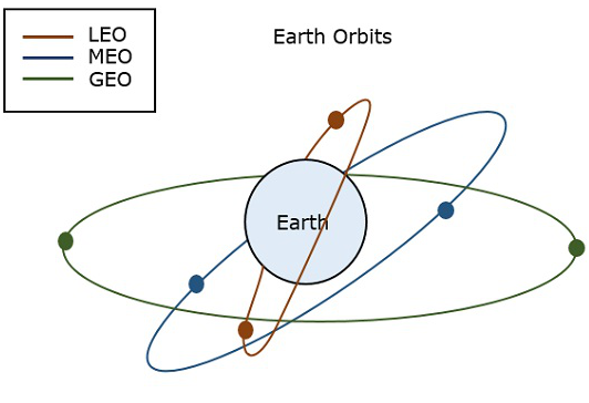
The fig given below depicts the paths of LEO, MEO and GEO
Orbital Slots
Now, question arises that with more than 200 satellites that are in geosynchronous orbit, how do we keep them from running into each other or from attempting to use the same location in space?
To answer this problem (question), international regulatory bodies like the International Telecommunications Union (ITU) and national government organizations like the Federal Communications Commission (FCC) designate the locations on the geosynchronous orbit, where the communications satellites can be located.
These locations are specified in degrees of longitude and are called as orbital slots. The FCC and ITU have progressively reduced the required spacing down to only 2 degrees for C-band and Ku-band satellites due to the huge demand for orbital slots.
Pros and Cons of Satellite Communication
Satellite Communication − Advantages
There are many Advantages of satellite communications such as −
- Flexibility
- Ease in installing new circuits
- Distances are easily covered and cost doesn’t matter
- Broadcasting possibilities
- Each and every corner of earth is covered
- User can control the network
Satellite Communication − Disadvantages
Satellite communication has the following drawbacks −
- The initial costs such as segment and launch costs are too high.
- Congestion of frequencies
- Interference and propagation
Satellite Communication − Applications
Satellite communication finds its applications in the following areas −
- In Radio broadcasting.
- In TV broadcasting such as DTH.
- In Internet applications such as providing Internet connection for data transfer, GPS applications, Internet surfing, etc.
- For voice communications.
- For research and development sector, in many areas.
- In military applications and navigations.
3.4 Mobile communication System
Mobile Communication is the use of technology that allows us to communicate with others in different locations without the use of any physical connection (wires or cables). Mobile communication makes our life easier, and it saves time and effort.
A mobile phone (also called mobile cellular network, cell phone or hand phone) is an example of mobile communication (wireless communication). It is an electric device used for full duplex two way radio telecommunication over a cellular network of base stations known as cell site.
Features of Mobile Communication
The following are the features of mobile communication:
- High capacity load balancing: Each wired or wireless infrastructure must incorporate high capacity load balancing. High capacity load balancing means, when one access point is overloaded, the system will actively shift users from one access point to another depending on the capacity which is available.
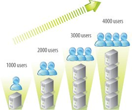
- Scalability: The growth in popularity of new wireless devices continuously increasing day by day. The wireless networks have the ability to start small if necessary, but expand in terms of coverage and capacity as needed - without having to overhaul or build an entirely new network.
- Network management system: Now a day, wireless networks are much more complex and may consist of hundreds or even thousands of access points, firewalls, switches, managed power and various other components.
The wireless networks have a smarter way of managing the entire network from a centralized point. - Role based access control: Role based access control (RBAC) allows you to assign roles based on what, who, where, when and how a user or device is trying to access your network. Once the end user or role of the devices is defined, access control policies or rules can be enforced.
- Indoor as well as outdoor coverage options: It is important that your wireless system has the capability of adding indoor coverage as well as outdoor coverage.
- Network access control: Network access control can also be called as mobile device registration. It is essential to have a secure registration.
Network access control (NAC) controls the role of the user and enforces policies. NAC can allow your users to register themselves to the network. It is a helpful feature that enhances the user experience.
- Mobile device management: Suppose, many mobile devices are accessing your wireless network; now think about the thousands of applications are running on those mobile devices.
How do you plan on managing all of these devices and their applications, especially as devices come and go from your business?
Mobile device management can provide control of how you will manage access to programs and applications. Even you can remotely wipe the device if it is lost or stolen.
- Roaming: You don't need to worry about dropped connections, slower speeds or any disruption in service as you move throughout your office or even from building to building wireless needs to be mobile first.
Roaming allows your end-users to successfully move from one access point to another without ever noticing a dip in a performance.
For example, allowing a student to check their mail as they walk from one class to the next. - Redundancy: The level or amount of redundancy your wireless system requires depends on your specific environment and needs.
- For example: A hospital environment will need a higher level of redundancy than a coffee shop. However, at the end of the day, they both need to have a backup plan in place.
- Proper Security means using the right firewall: The backbone of the system is your network firewall. With the right firewall in place you will be able to:
- See and control both your applications and end users.
- Create the right balance between security and performance.
- Reduce the complexity with:
- Antivirus protection.
- Deep Packet Inspection (DPI)
- Application filtering
- Protect your network and end users against known and unknown threads including:
- Zero- day.
- Encrypted malware.
- Ransomware.
- Malicious botnets.
- Switching: Basically, a network switch is the traffic cop of your wireless network which making sure that everyone and every device gets to where they need to go.
Switching is an essential part of every fast, secure wireless network for several reasons:- It helps the traffic on your network flow more efficiently.
- It minimizes unnecessary traffic.
- It creates a better user experience by ensuring your traffic is going to the right places.
Cellular Mobile System (GSM)
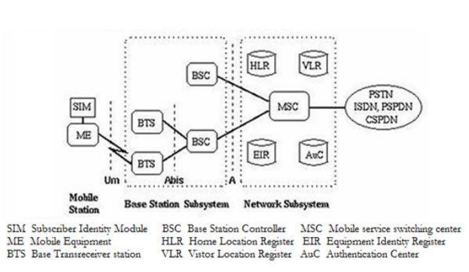
The GSM network architecture consists of three major subsystems:
Mobile Station (MS)
Base Station Subsystem (BSS)
Network and Switching Subsystem (NSS)
The wireless link interface between the MS and the Base Transceiver Station (BTS), which is a part of BSS. Many BTSs are controlled by a Base Station Controller (BSC). BSC is connected to the Mobile Switching Center (MSC), which is a part of NSS. Figure shows the key functional elements in the GSM network architecture.
Mobile Station (MS):
A mobile station communicates across the air interface with a base station transceiver in the same cell in which the mobile subscriber unit is located. The MS communicates the information with the user and modifies it to the transmission protocols if the air-interface to communicate with the BSS. The user’s voice information is interfaced with the MS through a microphone and speaker for the speech, keypad, and display for short messaging, and the cable connection for other data terminals. The MS has two elements. The Mobile Equipment (ME) refers to the physical device, which comprises of transceiver, digital signal processors, and the antenna. The second element of the MS is the GSM is the Subscriber Identity Module (SIM). The SIM card is unique to the GSM system. It has a memory of 32 KB.
Base Station Subsystem (BSS):
A base station subsystem consists of a base station controller and one or more base transceiver station. Each Base Transceiver Station defines a single cell. A cell can have a radius of between 100m to 35km, depending on the environment. A Base Station Controller may be connected with a BTS. It may control multiple BTS units and hence multiple cells. There are two main architectural elements in the BSS – the Base Transceiver Subsystem (BTS) and the Base Station Controller (BSC). The interface that connects a BTS to a BSC is called the A-bis interface. The interface between the BSC and the MSC is called the A interface, which is standardized within GSM.
Network and switching subsystem (NSS):
The NSS is responsible for the network operation. It provides the link between the cellular network and the Public switched telecommunicates Networks (PSTN or ISDN or Data Networks). The NSS controls handoffs between cells in different BSSs, authenticates user and validates their accounts, and includes functions for enabling worldwide roaming of mobile subscribers. In particular the switching subsystem consists of:
- Mobile switch center (MSC)
- Home location register (HLR)
- Visitor location Register (VLR)
- Authentications center (Auc)
- Equipment Identity Register (EIR)
- Interworking Functions (IWF)
The NSS has one hardware, Mobile switching center and four software database element: Home location register (HLR), Visitor location Register (VLR), Authentications center (Auc) and Equipment Identity Register (EIR). The MSC basically performs the switching function of the system by controlling calls to and from other telephone and data systems. It includes functions such as network interfacing and common channel signalling.
HLR:
The HLR is database software that handles the management of the mobile subscriber account. It stores the subscriber address, service type, current locations, forwarding address, authentication/ciphering keys, and billings information. In addition to the ISDN telephone number for the terminal, the SIM card is identified with an International Mobile Subscribes Identity (IMSI) number that is totally different from the ISDN telephone number. The HLR is the reference database that permanently stores data related to subscribers, including subscriber’s service profile, location information, and activity status.
VLR:
The VLR is temporary database software similar to the HLR identifying the mobile subscribers visiting inside the coverage area of an MSC. The VLR assigns a Temporary mobile subscriber Identity (TMSI) that is used to avoid using IMSI on the air. The visitor location register maintains information about mobile subscriber thatis currently physically in the range covered by the switching center. When a mobile subscriber roams from one LA (Local Area) to another, current location is automatically updated in the VLR. When a mobile station roams into anew MSC area, if the old and new LA’s are under the control of two different VLRs, the VLR connected to the MSC will request data about the mobile stations from the HLR. The entry on the old VLR is deleted and an entry is created in the new VLR by copying the database from the HLR.
AuC:
The AuC database holds different algorithms that are used for authentication and encryptions of the mobile subscribers that verify the mobile user’s identity and ensure the confidentiality of each call. The AuC holds the authentication and encryption keys for all the subscribers in both the home and visitor location register.
EIR:
The EIR is another database that keeps the information about the identity of mobile equipment such the International mobile Equipment Identity (IMEI) that reveals the details about the manufacturer, country of production, and device type. This information is used to prevent calls from being misused, to prevent unauthorized or defective MSs, to report stolen mobile phones or check if the mobile phone is operating according to the specification of its type.
White list: This list contains the IMEI of the phones who are allowed to enter in the network.
Black list: This list on the contrary contains the IMEI of the phones who are not allowed to enter in the network, for example because they are stolen.
Grey list: This list contains the IMEI of the phones momentarily not allowed to enter in the network, for example because the software version is too old or because they are in repair.
IWF (Interworking Function}:
It is a system in the PLMN that allows for non-speech communication between the GSM and the other networks. The tasks of an IWF are particularly to adapt transmission parameters and protocol conversions. The physical manifestations of an IWF may be through a modem which is activated by the MSC dependent on the bearer service and the destination network. The OSS (Operational Support Systems) supports operation and maintenance of the system and allows engineers to monitor, diagnose, and troubleshoot every aspect of the GSM network.
Advantages of Mobile Communication
There are following advantages of mobile communication:
- Flexibility: Wireless communication enables the people to communicate with each other regardless of location. There is no need to be in an office or some telephone booth in order to pass and receive messages.
- Cost effectiveness: In wireless communication, there is no need of any physical infrastructure (Wires or cables) or maintenance practice. Hence, the cost is reduced.
- Speed: Improvements can also be seen in speed. The network connectivity or the accessibility was much improved in accuracy and speed.
- Accessibility: With the help of wireless technology easy accessibility to the remote areas is possible. For example, in rural areas, online education is now possible. Educators or students no longer need to travel to far-flung areas to teach their lessons.
- Constant connectivity: Constant connectivity ensures that people can respond to emergencies relatively quickly. For example, a wireless device like mobile can ensure you a constant connectivity though you move from place to place or while you travel, whereas a wired landline can't.
References:
Dennis Roddy, “Satellite Communication”, 4th Edition, Mc Graw Hill International, 2006
Bruce R. Elbert, “The Satellite Communication Applications”, Hand Book, Artech House Bostan London, 1997.
Theodore Rappaport,“ Mobile Communication”, second edition, pearson education, 2010.
T. L. Singhal, “Wireless Communication System”, Tata McGrow-Hill Education, 2010.
M. Kulkarni, “Microwave and Radar Engineering”, third edition, Umesh Publication, 2008.