Unit - 1
Electrical System Components
(I) Surface switch: It can be attached to a wooden board fixed to the surface of the wall. There are 3 types
1. One-way switch
2. Bidirectional switch
3. Intermediate switch
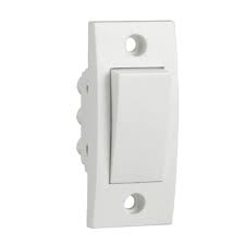
Fig 1 One-way switch
2. Bidirectional Switch: Used to divert the current flow in either of the two directions. You can also use a bidirectional switch to control one ramp from two different locations, as in the case of stairway wiring. (Fig. 1.2).
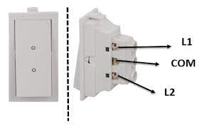
Fig 2 Two-way switch
3. Intermediate Switch: Used to control the lamp from 3 or more locations (Fig. 1.3).
Fig 3 Intermediate Switch
i. Flush Switch: It used for decorative purpose (Fig. 1.4).

Fig 4 Flush Switch
ii. Bed Switch: As the name implies, it is used to turn the light "on" from a location other than the switchboard or near the bed. This switch is connected with a flexible wire (Fig. 1.5).

Fig 5 Bed Switch
B. Holders: A holder is of two types.

Fig 6 Pendant Holder
2. Batten holder (Fig. 1.7)

Fig 7 Batten Holder
C. Ceiling Rose: Used to provide tapping to the pendant lamp holder via a flexible wire or connection to a fluorescent light (Fig. 1.8).

Fig 8 Ceiling Rose
D. Socket Outlet / Plug: The socket outlet has an insulating base and the molded or socket base has three terminal sleeves (Fig. 1.9).

Fig 9 Socket
E. Main Switch: The main switch is used to control the electric circuit. Through the main switch, the power inside the building is fully controlled (Fig. 1.10).
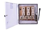
Fig 10 Main Switch
F. PVC Casing Capping Wiring: PVC capping is done to cover the wires. Casing is also included. This casing capping wiring is also called open wiring because it is done outside the wall. The materials required for PVC casing capping wiring (Fig 1.11 and 1.12) are 1. Wire 2. Plastic Casing Enclosure 3. Plastic Capping 4. T. Joint VIR (Vulcanized Indo Rubber) or PVC (Polyvinyl Chloride) Included.) Insulated wires 5. Junction box 6. Elbow 7. Casing and capping joint Wooden Casing-Capping wiring is archaic. Currently, PVC or VIR insulated wire is enclosed within a PVC casing enclosure and PVC capping is used to cover the casing.
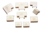
Fig 11 PVC Casing Capping Accessories
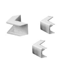
Fig 12 PVC Casing Capping Bend
Miniature Circuit Breaker (MCB): MCB is used in new construction instead of old type fuses. Circuit breakers are small devices used to control electrical panels and other devices and protect them from power overflows (Fig. 1.13).
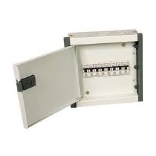
Fig 13 MCB distribution box
Key takeaways:
Switches are used to create or disconnect electrical circuits. Used to switch the power supply to the appliance "on" or "off".
Electric cables are the nerve of any electrical network. Cables make up the majority of capital investment in electrification projects. And they are also the most vulnerable to failure. Most cable failures can be due to improper selection. This article aims to address the issue of proper power cable selection.
Selection Parameters
I. Rated Voltage: This is the rated voltage of the system in which the cable is installed and used. It is also important to know how to ground the system. The rated voltage of the cable is usually specified as a dual rating (eg 6.6kV (UE) / 11kV (E)).
"UE" means that the cable can be used at the specified voltage in an ungrounded or effectively ungrounded system. An "E" means that the cable can be used at the specified voltage in a well-grounded system. Therefore, cables with rated voltages of 6.6kV (UE) / 11kV (E) can be used with either 6.6kV non-earthing systems, 6.6kV non-effective earthing systems, or 11kV solid earthing systems. I will.
II. Conductor Type: The most commonly used conductors in cables are either copper or aluminium. As is known, for the same voltage rating, type, insulation, cross-sectional area, and installation method, the continuous current rating, short-time current rating, and cost per unit length of copper cable are significantly higher than aluminium. Become. cable.
III. Insulation Type: Most cables today are insulated with either PVC or XLPE. Obviously, for the same conductor material, voltage rating, type, insulation, cross-linked area, and installation method, the continuous current rating, short-time current rating, and cost per unit length of the XLPE insulated cable are significantly higher. Become. PVC insulated cable.
IV. Cable Types: Armored or unarmored cables are used in indoor equipment and ground equipment such as cable trays and pre-built concrete cable trenches. An armored cable is required to install the underground cable.
V. Continuous Current Ratings: Continuous current ratings for cables with aluminium / copper conductors are available in the catalog of various cable manufacturers. However, keep in mind that these catalog list continuous current ratings for certain standard installation conditions. In reality, it is not possible to obtain or maintain these standard conditions. Therefore, certain rating factors are applied to reach the actual continuous current rating.
VI. Evaluation Factors: The general evaluation factors to consider are:
a) Rating factor for fluctuations in ground temperature or duct temperature
b) Evaluation coefficient for fluctuations in ambient temperature
c) Evaluation coefficient for fluctuations in soil thermal resistance
d) Group evaluation factor – vertical spacing
e) Group evaluation factor – horizontal spacing
All these rating factors for different conditions are also available in the cable manufacturer's catalog.
VII. Voltage Drop: The cable consists of a resistor and reactance. Therefore, the current flowing through such impedance causes a voltage drop. This reduction should not affect the cabled load.
The actual voltage drop of the cable is indicated by V / km / A in the cable manufacturer's catalog for different types of cables. It is also stipulated in the Indian standard IS 1255 (implementation standard for installation and maintenance of power cables up to 33 kV rating).
It is necessary to calculate not only the steady-state voltage drop, but also the accelerated state voltage drop at the start of a large load.
It is also necessary to confirm that the steady-state voltage drop at the load terminal is 10% or less and the accelerated voltage drop at the load terminal is 15% or less.
Wire selection
When choosing a wire or cable, there are actually three overall properties: physical performance, functional performance, and supportability. Physical performance identifies how well the overall structure can withstand environmental stresses such as wear, thermal fluctuations, installation, and exposure to fluids and contaminants. Functional parameters take into account signal attenuation and how well the wires / cables handle current surges without causing smoke or fire hazards. Finally, supportability considers how human factors and long-term maintenance needs for equipment play a role throughout the maintenance cycle.
Physical Parameters
When choosing a wire / cable, the most important physical parameters are temperature, fluid exposure, installation, and performance when exposed to wear at operating temperatures. In terms of temperature, insulation and conductor limits need to be considered. For shielded cables, shielded plating should also be considered as a limiting factor. When a conductor overheats, the plating deteriorates rapidly, the conductivity decreases, the signal deteriorates more, and it becomes more susceptible to corrosion.
For liquid exposure, many aircraft wire / cable insulation types are inert to common chemicals, which should be evaluated according to the application. If unusual chemicals are used in either manufacturing or maintenance of the platform, the suitability of the material should be evaluated. There are some recent examples of fleets that have implemented new cleaning or deicing solutions just to cause significant deterioration of electrical components. Tests such as AS4373 Method 601 provide the basis for assessing wire / cable degradation due to fluid exposure.
Abrasion resistance should be evaluated at operating temperature. How wire insulation works at ambient temperature is not the same as how it works at high temperatures. A rise of only 10 ° C can reduce the performance of some insulation types by up to 50%. These performance changes do not have to be above 140 ° C, but in some cases can range from 50oC to 60 ° C. If the environment in your installation zone is vibrating or subject to regular maintenance traffic, we recommend that you choose components that are highly wear resistant.
Functional Performance
Functional reliability of wires / cables is necessary to ensure that everything else in the aircraft works. But what are the parameters that need to be selected or evaluated when selecting a wire? The three factors Lectromec recommends are current capacity, signal degradation, and voltage rating.
For current capacity, there is already a wealth of information on recommended maximum current ratings for various gauge wires. Lectromec already has some articles on this. This maximum current rating is usually derated when added to the wire harness.
Signal integrity is an important attribute of RF microwave and high-speed data cables. The signal deteriorates as it travels over the wire. Cable signal degradation is frequency dependent and inconsistent throughout the frequency spectrum. The higher the frequency, the greater the attenuation of the signal. The acceptable attenuation level depends on the application / equipment / installation, and more than one cable works for every application. Since signal integrity largely depends on the shape and electrical conductivity of the cable, it is important to consider the bend radius and routing. , And other environmental stressors. Most signal attenuation concerns can be resolved by choosing the correct cable that has been thoroughly tested for application requirements.
Finally, you need to consider the rated voltage of the wire or cable. The nominal voltage of a circuit can be 115V, but transients from either the load or the power supply often cause power spikes at voltages that are more than two or three times the nominal voltage. In pulse width modulation systems, these transients are common and frequent.
As a result, the stress on the wire / cable dielectric increases. When considered independently, voltage spikes and increased power system frequencies are not an issue, but the combination of the two can cause rapid dielectric degradation. It is advisable to recognize these voltage spikes and choose a wire with the corresponding permanent insulation performance.
Supportability
Supportability is considered last here, but should not be considered a retrofit.
Supportability is the idea that once a part is selected, it needs to do the following:
Each supportability factor is a basic logistical consideration for all components, and all wires, cables, or connectors placed on an aircraft should be given the same consideration. Choosing a component that is no longer available after 10 years, or a component that cannot be maintained due to missing tools, only causes problems.
Often, the best way to address supportability concerns is to use one that adheres to the latest industry standards. This is because others are using the same components and are likely to face similar support concerns. This makes it more likely that the component will remain available for years to come.
Distribution Box Selection
"Distribution box", also called distribution cabinet, is a general term for motor control centers. A power distribution box is a low-voltage power distribution that can be assembled on a closed or semi-closed metal cabinet or screen with switchgear, measuring instruments, protective equipment, and auxiliary equipment, depending on your electrical wiring requirements.
The main functions are "power generation", "transmission", "transformer", "distribution", first always power generation, then step-up transformer, then power supply. After changing the high voltage to a high voltage, it is transported to various locations, the transformer is gradually changed to the required voltage, and finally it is transported to the electrical equipment transported via the distribution equipment.
When transforming a distribution box, you must first consider the safety of this distribution box. The ideal distribution box should have the following configuration:
Number of Loops
The optimum number of distribution box circuits (electric gates) should be 1 + X + Y + Z. 1 points to the main switch. X indicates the number of rooms used to control the normal sockets in each room. Y indicates the number of high-power appliances used to control all high-power appliances (all appliances that require the use of surface mounted circuit breakers or 16A 3-hole sockets are high It is an output electric appliance). Z represents the number of lighting circuits (2-3 for lamps). For loops, you usually use one loop).
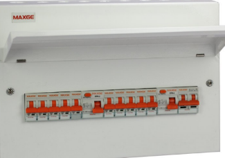
Fig 14 Distribution Box
Number of Poles
Household circuit breakers are divided consistent with the amount of only three poles: 1P, 1P + N, and 2P. The difference between these three poles is that the 1P breaker can only control the on and off of the live line and protect the live line. The 2P breaker simultaneously controls the zero line on and off while protecting the zero line. The 1P + N circuit device is within the middle. you'll only control the Fireline on and off, but at an equivalent time protect the neutral and live lines. Therefore, it's known that 2P circuit breakers are the simplest and only 1P + N.
Function Selection
The air switch has two protection functions: overload protection and short protection. Additionally, to the protection, you would like to feature additional accessories. There are two commonly used accessories within the home: leak protectors and "overvoltage and undervoltage releases". the previous is employed for circuit breakers in each socket (including regular sockets and 3-hole sockets). The latter only must be installed on the most switch.
Practicality
Distribution boxes configured consistent with the previous method can guarantee absolute security. However, there are two problems.
The reason for these two problems is that there are too many circuits within the distribution box and too many poles. Therefore, if you would like your distribution box to be practical, you would like to start out with these two aspects. Loop reduction the perfect number of loops is 1 + X + Y + Z, and therefore the main switch and lighting loops can't be changed. it's lost thanks to the tiny number of loops. The Y (high power electricity) circuit can't be changed either. High power appliances must use separate circuits and will be retained if not in use. Therefore, what we would like to scale back is that the X (number of rooms) loop.
Weighing System Selection
The metering system consists of things of metering equipment. Voltage transformers, current transformers, meters and outstations, wiring and connections between items, and therefore the connections needed to transfer metered data to the surface world (modems, communication lines, etc.).
There are many factors to think about when choosing the proper electric meter. Whether for tenant submetering, commercial building submetering, power monitoring for energy management, or other applications, the wattmeter must meet certain specifications. Although each application has its own requirements, there are some common factors to gauge. When considering electric meter options, it's important to understand the following:
Application overview
The two most vital things to understand when choosing an influence meter are defining what you would like to live and what data you're trying to urge from the meter. These helps outline what the meter must neutralize the appliance to supply the knowledge at the specified level of particle size.
If your monitoring application may be a residential or light commercial vehicle, you'll need a wattmeter to handle single-phase or single-phase loads. These applications use approximately 120-240 VAC and consume less current than three-phase applications.
Applications that need a three-phase meter include chillers, air handling units (AHUs), and process equipment. Three-phase power supplies 1.7 times more power than single-phase power with an equivalent current. Three-phase motors can handle current ranges up to 480 amps, up to 480 BACS.
Using the service types outlined, subsequent decision is that the number of loads that your application is trying to live. The load can contain the availability voltage and current consumption of the whole building, switchboard, or one piece of kit. The service type determines the amount of current transformers (CTs) required to live the load. for instance, a single-phase load like a light circuit may require just one CT, while a three-phase load like a chiller requires 3 CT. Multi-load meters save time and reduce overall investment when many load measurements are required to completely support an energy management strategy. However, if you would like to live only the most a part of the building, you'll use one load gauge to satisfy the requirements of your application.
Mounting Requirements
Most electrical rooms have limited space when installing a power meter, especially if a NEMA 1 enclosure is required for safety. Before installation, it is important that the meters (and enclosures, if necessary) fit in the proper space. Knowing the mounting direction of the meter will help you determine if the meter fits in the desired space.
All fittings must comply with the National Electrical Code (NEC). When connecting to a power source, it is recommended that the voltage leads be connected through an electric breaker with properly sized wiring.
Types of Current Transformers
The two most common types of current transformers used in wattmeter’s are the split / solid core CT and the Rogowski coil. The requirements of your application determine the type of current transformer you use. Busbars and irregularly shaped cable bundles are common in applications with high power requirements, so it is advantageous to use Rogowski coils.
The most obvious distinction between a traditional CT or Rogowski coil for an application is the current measured. Traditional CTs are typically low cost with a low amp range of less than 200A, but Rogowski coils can handle up to 6,000A and a single part number can cover a wide range of amps.
Once you know the CT to use, select a wattmeter that accepts those inputs. If you are unsure of the CT type when choosing a meter, it is best to choose one that accepts both traditional CT and Rogowski coils.
Communication Settings
The wattmeter can communicate in a variety of ways, including pulse, BACnet, and Modbus. Pulse output is common in single-phase applications where the end user needs less information. Meters using advanced protocols such as BACnet and Modbus have the ability to communicate all parameters through a building automation system, providing end users with a more complete picture of their consumption data. I will. The best communication protocol for your application depends on the level of detail required for the output information and how the information is collected.
Field Configuration
Installing a preset meter that does not have the flexibility or ability to change in the field can cause problems if the preset meter is incorrect. A power meter with the flexibility to be configured in the field is very beneficial. These meters reduce the risk if the wrong CT type is ordered, if the communication protocol is different than expected, or if the voltage service is not covered by preconfigured meters. Adaptability to changes in the field is often overlooked, but it is important for the proper performance of the meter.
Total Installation Cost
All the considerations so far affect the total installation cost. Total installation costs include meter purchase price, labor costs, project compatibility, and effectiveness. This cost helps the contractor better understand all the potential costs that can be incurred at work. When calculating total installation costs, do not overlook auxiliary items that may be needed for the meter of interest, such as fused reeds or NEMA-rated enclosures. Before choosing a power meter, make sure that all application requirements are clear to the installer.
Selection of Fee Structure
The utility charge structure (or rate structure) often determines the economic feasibility of a distributed generation system. This pricing structure typically consists of energy charges (kilowatt hours purchased per billing period) and demand charges (peak demand during the billing period).
All of our homes are well powered and we pay the government for that. Now let's talk about the cost of powering each home monthly / yearly. It can be expressed in terms called tariffs.
The price at which electrical energy is given to consumers is known as the charge. The price must include the total cost and profit of producing and supplying electrical energy, but it cannot be the same for all types of consumers. This is because the cost of producing electrical energy depends to a large extent on the amount of electrical energy consumed by the user and the load conditions of the user. Therefore, for fairness, careful consideration must be given to different types of consumers (industrial, domestic, commercial, etc.) when determining rates. This greatly complicates the issue of proper rates.
Purpose of the Price: Like other products, electrical energy is sold at such a rate, so you can not only return the cost, but also get a reasonable profit. Therefore, the price should include the following items:
a) Recovery of electrical energy production costs at power plants.
b) Recovery of capital investment costs for power transmission and distribution systems.
c) Recovery of the cost of operation and maintenance of the supply of electrical energy (e.g., weighing equipment, billing, etc.).
d) Appropriate return on capital investment.
Desirable Properties of Tariff:
The tariff must have the following desirable properties of the tariff:
Similarly, consumers whose load conditions do not deviate significantly from their ideals, that is, non-variable consumers, need to charge at a lower rate than consumers whose load conditions have changed significantly from their ideals.
3. Simplicity: The price should be simple for the general consumer to understand. Complex charges can cause opposition from the general public, who generally distrust the supplier.
4. Reasonable Profit: The profit factor of the fee must be reasonable. Power companies are utilities and generally benefit from monopolies. Therefore, the investment is relatively safe as there is no competition in the market. This requires that profits be limited to around 8% per year.
5. Attractive: Prices must be attractive so that many consumers are encouraged to use electrical energy. Efforts should be made to fix prices in a way that consumers can easily pay.
Key takeaways:
Protection Component: A component that helps prevent a failure from becoming a disaster.
Fuse: The fuse is a protector. These are safety devices used to protect home appliances such as televisions, refrigerators and computers from damage caused by high voltage. A fuse is made up of thin strips or metal strands that, when a large amount of current or excess current flows through an electrical circuit, melts the fuse, opening the circuit and disconnecting it from power. It also acts as a circuit breaker or stabilizer that protects the device from damage. There are many types, features, and designs of fuses on the market today. These strips are made of aluminum, copper and zinc and are always connected in series with the circuit to protect them from overcurrent in the wiring cables. Here are the basic schematics and symbols of the fuse.
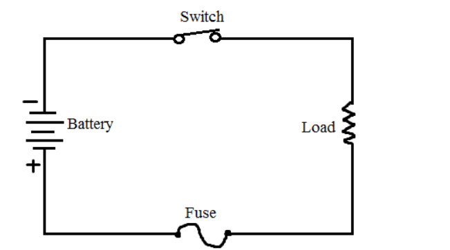
Fig 15 Circuit Diagram of Fuse

Fig 16 Symbol of Fuse
Fuse Needs: Fuse is used to prevent damage to home appliances due to short circuits, overloads, high currents, etc. Failure to use fuses can cause electrical damage to the wiring and can burn wires and electrical equipment fire at home. The lives of televisions, computers, radios and other consumer electronics can also be at risk. If the fuse blows, a sudden spark will occur, and turning off the power can cause the house to suddenly darken. This will prevent further accidents. Therefore, fuses are needed to protect home appliances from harm.
Fuse Operation: The fuse operates on the principle of the heating effect of electric current. It consists of thin strips of non-flammable material or strands of metal wire. It is connected to both ends of the terminal. The fuse is always connected in series with the electrical circuit.
When a large current flow through the circuit and excessive current or heat is generated, the fuse melts and the circuit open because the melting point of the element is low. Excessive flow can lead to wire breakage and stop current flow. The fuse can be replaced or replaced with a new fuse of the appropriate rating. Fuse can be composed of elements such as zinc, copper, silver and aluminium. It also acts as a circuit breaker used to break the circuit in the event of a sudden circuit failure. This is not only a protective device, but also used as a safety measure to prevent danger to the human body. So, this is how the fuse works. It is the figure which showed the operation of the fuse, the fuse barrel (container), and the fuse link.
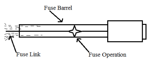
Fig 17 Working Operation of Fuse
Fuse Features:
Current (Cin) = 75% current (rated)
2. Voltage Rating: With this characteristic, the voltage connected in series with the fuse does not increase the voltage rating. In other words
V (fuse)> V (open ckt)
3. I2t Rating: This is the amount of energy carried by the fuse element in the event of an electrical failure or any short circuit. It is generated when the fuse blows by measuring the thermal energy (energy due to electric current) of the fuse.
4. Breaking or Breaking Capacity: This is the maximum rating of current without breaking by the fuse and is known as the breaking or breaking capacity of the fuse.
Breaking capacity> Maximum rated voltage
Breaking capacity <short ckt current
5. Voltage Drops: Excessive current will melt the fuse element and open the circuit. This resistance change reduces the voltage drop.
6. Temperature: This will increase the operating temperature, lower the rated current and melt the fuse.
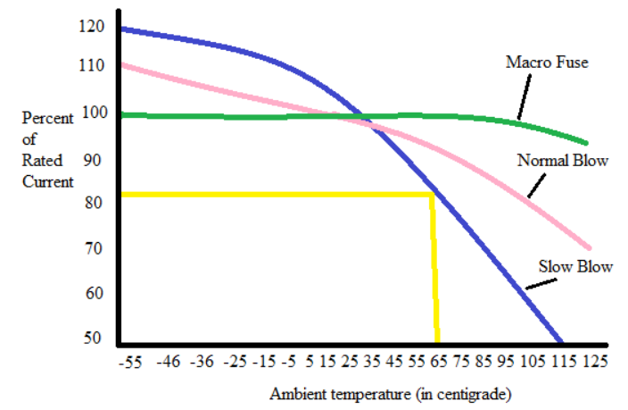
Fig 18 Characteristic of Fuse
This graph shows the relationship between temperature and fuse current capacity. In this process, the current capacity of the fuse reaches 100% when the three wires meet at 25 degrees Celsius, and after a while, the slow blow fuse reduces the current capacity, and at 65 it decreases by up to 82%. This reduces the ampacity of the fuse as the temperature rises.
Fuse Classification:
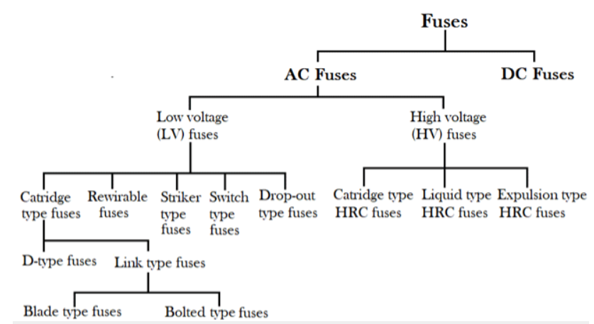
Fig 19 Classification of Fuses
There are two types of fuses: -
AC fuses are further divided into two parts: low-voltage fuses and high-voltage fuses.
a) Cartridge Type Fuse: This is a type of fuse that has a completely sealed container and is in contact.
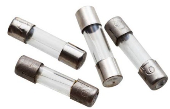
Fig 20 Cartridge Type Fuses
There are two types of Cartridge type fuses: -
a) Blade Type / Plug-in Type: -The body of this fuse is made of plastic and can be easily replaced in the circuit without any load.
b) Bolted Type: -For this type of fuse, the conductive plate is fixed to the fuse base.
3. Rewireable / Kit kat Type: -The main advantage of this type of fuse is that the fuse carrier can be easily removed without electric shock or injury. The fuse base acts as an input and output terminal made of porcelain, and the fuse carrier is used to hold the fuse element made of tin, copper, aluminium, lead, etc. It is used in domestic wiring, small industry. etc
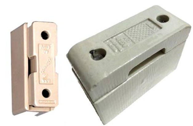
Fig 21 Rewireable/ Kit-Kat Type Fuses
Striker Type Fuse: -This type of fuse is used to close and trip the circuit. They have enough force and displacement.
Switch-Type Fuses: -This type of fuse is basically a metal surrounded by switches and fuses and is widely used at low and medium voltage levels.
Dropout Fuse: -In this type of fuse, when the fuse melts, the element will fall around the lower support under gravity. They are made for the protection of outdoor transformers.
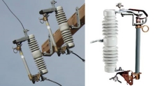
Fig 22 Drop out Fuses
2. High voltage fuse (HV):
All types of high voltage fuses are used at rated voltages up to 1.5 Kv to 138 Kv. High voltage fuses are used to protect instrument transformers and small transformers. Made of silver, copper and tin. When heat is generated, an arc is generated and boric acid produces a large amount of gas. Therefore, they are used outdoors.
There are three types of these: -
a) Cartridge Type HRC Fuse: -Similar to the low voltage type, except for some design features.
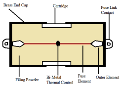
Fig 23 Cartridge Type HRC Fuses
b) Liquid Type HRC Fuses: -These are used for circuits with up to 100A rated current and systems up to 132Kv. The glass tubes of these fuses are filled with carbon tetrachloride. One end of the tube is packed and the other end is secured with phosphor bronze wire. When the fuse is activated, the liquid in the fuse extinguishes the arc. This will increase the short circuit capacity.
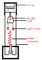
Fig 24 Liquid Type HRC Fuse
c) Ejection Type HRC Fuse: -This is an escapable fuse that has the effect of exhausting the gas produced by the internal arc. In this case, the fuse link chamber is filled with boric acid to expel the gas.
d) Resettable Fuse: -This is a type of fuse commonly known as a self-reset fuse that uses a thermoplastic conductive type thermistor known as the Polymer Positive Temperature Coefficient (PPTC). When a failure occurs. The current increases and the temperature rise. The increase in resistance is due to an increase in temperature. The applications in which it is used are non-exchangeable military and aerospace.
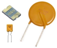
Fig 25 Resettable Fuses
MCB:
At that time, we used fuse wires to protect against overcurrent (in fact, we were selling it!). The principle was pretty simple. Overcurrent literally heats and melts the fuse wire rapidly, "blowing" the fuse wire by breaking the electrical connection, thus protecting the rest of the electrical circuit.
This is enhanced because MCBs are usually not destroyed during overcurrent and can be reused. They are also much easier to use, provide "on / off" convenience for circuit insulation, and the conductors are housed in a plastic casing, making them much safer to use and operate.
It is important to note that MCBs do not protect humans from electric shocks caused by "leakage". This service is provided by RCD and RCBO.
MCBs have three main characteristics:
a) Amps,
b) Kiloamps, and
c) Tripping curves.
Overload Current Rating-Amps (A)
Overload occurs when too many appliances are placed in a circuit and draw more current than the circuit and cables are designed to consume. This can happen in the kitchen, for example, if a kettle, dishwasher, electric stove, microwave oven, and blender are all used at the same time. The MCB in this circuit cuts off power to prevent overheating and fire of cables and terminals.
Short Circuit Rating-Kiloampere (Ka)
Short circuits are the result of a failure somewhere in an electrical circuit or appliance and are potentially much more common.
Overloads are more dangerous than overloads because the magnitude and speed of overcurrent’s vary by orders of magnitude. This happens when there is a direct connection between the live and neutral lines. In the absence of the resistance provided by normal circuit integrity, current flows around the circuit in a loop, multiplying amperes by thousands in just a few milliseconds.
MCBs used in domestic equipment are typically rated at 6kA or 6000 amps. The relationship between normal voltage (240v) and the power rating of common household appliances means that the overcurrent caused by a short circuit should not exceed 6000 amps. However, in commercial and industrial situations, when using 415v and large machines, it is necessary to use MCB rated at 10kA. These ratings indicate the maximum expected fault current (PFC) that the MCB can withstand and operate properly by disconnecting the circuit. Exceeding the PFC can cause the MCB to fail and stop welding the contacts.
How MCB Works:
1. Latch
2. Solenoid
3. Switch
4. Plunger
5. Incoming terminal
6. Arc chute holder
7. Arc chute
8. Dynamic contact
9. Fixed contacts
10.DIN rail holder
11. Outgoing terminal
12. Bimetal strip carrier
13. Bimetal strip
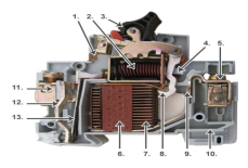
Fig 26 MCB
The MCB protects against both overloads and short circuits.
These two types of over currents are so different that the MCB detects and processes them as follows:
1) Thermal operation
2) Electromagnetic operation
Overload protection is provided by a bimetal strip (number 13 in the figure). During the "slow" continuous overcurrent characteristic of overload, the bimetal strip is heated by the charge and bends, releasing the mechanical latch. The latch connected to the operating mechanism opens the contacts and breaks the circuit.
During a short circuit, a sudden and dramatic increase in current causes the plunger (4) to electromechanically displace from the trip coil or solenoid (2). When the plunger hits the trip lever, the latch mechanism is immediately released, the contacts open and the circuit breaks.
Tripping Curve
The MCB's "tripping curve" allows for real-world, sometimes completely needed, power spikes. For example, in a commercial environment, large machines typically require an initial surge of power that exceeds normal operating current to overcome the inertia of large motors. This short surge, which lasts only a few seconds, is allowed by the MCB because it can be safely performed in this very short time.
There are three main curve types that allow surges in different electrical environments.
MCCB:
MCB is basically a miniature circuit breaker because it is used in motor feeders for up to 100 amps. MCCB (Full Foam: Molded Case Circuit Breaker) is used for motor feeders from 250 amps to 800 amps. This circuit breaker system basically protects the entire electrical system from conditions such as overload and short circuit problems. Simply put, these are electrical protection gadgets primarily used over a wide range of voltages, as the commonly known MCCBs have adjustable trip settings and can hold up to 2500 amps at rated current. Small circuit breakers, also known as MCCBs, automatically circuit electrical circuits in the event of a network anomaly that could mean an overload condition or a failure condition that is now widely used in place of low-voltage electrical networks. It is a gadget to turn off. The use of fuses for handling MCBs is electrically safer than the use of fuses.
MCCB systems include temperature-sensitive devices, also known as thermal elements, as well as current-sensitive electromagnetic devices, also known as magnetic elements, to provide a reliable overall trip mechanism for protection and isolation purposes. To use. MCCB basically utilizes a temperature sensitive device, also known as a thermal element. Current-sensitive devices are magnetic elements that provide protection and insulation that allow MCCB devices to provide overload protection and all types of electrical fault protection. Electric switch for short circuit and immediate disconnection.
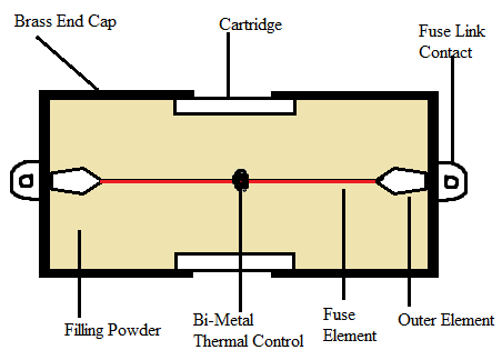
Fig 27 MCCB
According to the fact of overload protection, MCCB systems are provided via temperature sensitive components inside, which are essentially bimetal contacts. This type of contact, which is essentially composed of two metals, expands at different rates when exposed to higher levels of temperature, and under normal operating conditions, the bimetal contact allows current to flow through the MCCB system.
When the total value of the current exceeds the trip amount, the coefficient of thermal expansion of the thermal expansion limit for the chemical structure is different, so the bimetal contact becomes hot and begins to bend. Eventually what the contacts physically push the trip bar, unlatch the contacts, interrupt the circuit, and protect the entire electrical system from all types of unwanted situations.
Following electrical fault protection against short-circuit currents, the MCCB provides a quick response to short-circuit faults based on electromagnetic principles. When a short circuit failure occurs inside the entire electrical circuit, a large current begins to flow in the solenoid, resulting in the establishment of a strong electromagnetic field there, which basically attracts the trip bar and opens the contacts.
The MCCB can also be used as a device for a manual disconnect switch in an emergency, in addition to all trip mechanisms. It can also be used for all types of maintenance operations because it can create arcs within range when the contacts open to each other.
Different types of MCCB:
There are five different types of MCCB.
a) Type b
b) Type c
c) Type d
d) Type k
e) Type z
Type b MCCBs have an operating current range of 3 to 5 times the overall rated current and a 13 second operating response with a minimum and maximum limit of 0.04 seconds. It is well suited for home applications, as well as resistive load applications with low surge currents.
Type c MCCB trips between 5 and 10 times the rated current input, with response times from a minimum limit of 0.04 seconds to a maximum limit of 5 seconds, suitable for commercial or industrial purposes and inductive load applications with moderate surge currents. Combine.
Type d MCCB trips at 10 to 20 times the total rated current input, with a minimum response time of 0.04 seconds and a maximum limit of 3 seconds, for commercial or industrial application purposes and inductive capacitive load applications such as foam. Combines compatibility. Or a motor or a large vending machine motor.
MCCBs of type k and type z train 2-3 times the rated current input with a minimum response time of 0.04 seconds and a maximum response time of 5 seconds. It is basically very sensitive to shunts and is mainly used for high current production. Sensitive devices, such as semiconductor devices, are a subsidiary of IT equipment distribution boards and are suitable for medical devices, with very low surge current levels.
ELCB: Early earth leakage breakers were voltage detection devices, currently switched by current detection devices (RCD / RCCB). A current detection device, commonly referred to as an RCCB, and a voltage detection device, called an earth leakage breaker (ELCB). The first current ECLB was introduced 40 years ago, and the first voltage ECLB was introduced about 60 years ago. For several years, ELCBs that operate on both voltage and current were both called ELCBs because of their easy-to-remember names. However, the application of these two devices has contributed to a significant turmoil in the electrical industry.
ECLB is a type of safety device used to install electrical equipment with high ground impedance to prevent electric shock. These devices identify small stray voltages of electrical devices on metal enclosures and break into circuits if dangerous voltages are identified. The main purpose of the earth leakage breaker (ECLB) is to prevent damage to humans and animals due to electric shock.
The ELCB is a specific type of latching relay in which the input mains of the structure are associated through switching contacts, causing the circuit breaker to disconnect in a dangerous manner. The ELCB is aware of human or animal fault currents to the ground wire of the connecting connection it protects. If the ELCB sense coil appears to have sufficient voltage, it will be powered off and will remain off until manually repositioned. Voltage detection ELCB does not detect the fault current from humans or animals to the earth. The ELCB is aware of human or animal fault currents to the ground wire of the connecting connection it protects. If the ELCB sense coil appears to have sufficient voltage, it will be powered off and will remain off until manually repositioned. Voltage detection ELCB does not detect the fault current from humans or animals to the earth.
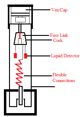
Fig 28 Earth Leakage Circuit Breaker
Functions and Operation of ELCB: The main function of the earth leakage breaker or ELCB is to prevent shock during installation of electrical equipment through high ground impedance because it is a safety device. This circuit breaker identifies a small stray voltage at the top of an electrical device with a metal housing and breaks the circuit if a dangerous voltage is identified. The main purpose of ELCB is to avoid harm to humans as well as animals due to electric shock.
An electrical circuit breaker is a particular type of latching relay that has a building main connected to the entire switching contact so that the circuit breaker disconnects when an earth leakage is identified. By using this, the fault current can be detected from the life of the fitting it protects to the ground wire. When enough voltage is applied to the sense coil of the circuit breaker, it is powered off and remains off until it is physically reset. The ELCB used for voltage detection does not detect fault currents.
ELCB connection: With ELCB, the ground circuit is compatible. The connection to the ground rod is accepted via an earth leakage breaker by linking to two ground terminals. One is connected to the fitting ground circuit protection conductor (CPC) and the other is connected to the ground rod or another type of ground connection. Therefore, the ground circuit can pass through the ELCB sense coil.
Types of Earth Leakage Breakers (ELCB)
There are two types of earth leakage breakers (ELCB)
a) Voltage actuated ELCB
b) Currently operating ELCB
Voltage Actuated ELCB
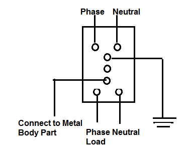
Voltage-operated ELCB devices are used to detect voltage and select earth leakage. The single-phase voltage ELCB contains six terminals: line input, line output, neutral input, neutral output, ground, and fault. The metal body of the load is associated with the earth leakage breaker (ELCB) fault terminal, and the ground terminal is associated with ground. In normal operation, the voltage across the trip coil is "0" because the body of the load is isolated from the supply line.
When a ground fault occurs in the load due to the interaction between the wire and the metal body, a current flow from the ground fault to the ground fault. The current flow sets the voltage across the trip coil associated between E and F. The energized trip coil tours the circuit to protect the load device and the user.
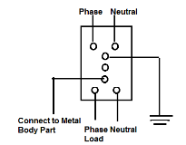
Fig 29 Voltage Operated ELCB
The voltage-operated ELCB detects an elevated potential between the consistent metalwork under threat and a remote isolated earth reference electrode. These act as a detection potential of approximately 50V, opening the main breaker and isolating the power supply from the threatening facility. The voltage-operated ELCB contains a second terminal for linking to a remote reference ground connection.
Using ELCB improves the ground circuit. The link to the ground rod is delivered via the ELCB by linking to the two ground terminals on the ELCB. One terminal energy is connected to the installed ground circuit protection conductor, also known as the ground wire (CPC), and the other is connected to the ground rod or some kind of ground connection.
ELCB currently in operation
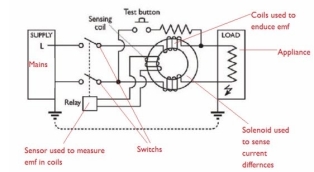
The RCCB is a commonly used ELCB and consists of a 3-winding transformer with two primary windings and one secondary winding. The neutral wire and the line wire act as two main windings. The winding coil is a secondary winding. In the stable state, the current flowing through the secondary winding is "0". In this state, the magnetic flux flowing by the current flowing through the phase line is deactivated by the current flowing through the neutral line, while the current flowing from the phase is returned to the neutral point.
When an error occurs, a small amount of current also flows to the ground. This creates confusion between the line current and the neutral current, creating an unstable magnetic field. This allows current to flow through the secondary windings associated with the detection circuit. This will detect the spill and send a signal to the trip system.
Key takeaways:
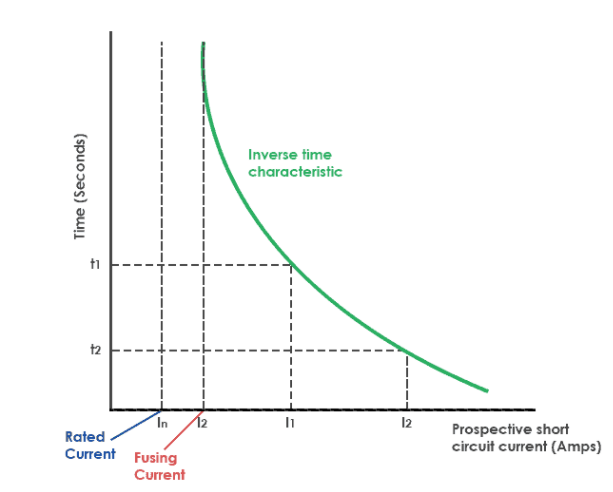
Fuse Time-Current Characteristics:
This figure shows one of the most important specifications of a fuse, the time-current characteristic. The graph shows the relationship between the current of the fuse element and the melting time. This shows how fast the fuse responds to different levels of overcurrent conditions. All fuses have the opposite time-current characteristics.
The time required to blow a fuse depends on the magnitude of the overcurrent. Therefore, the higher the current, the shorter the melting time for the fuse (the higher the overcurrent, the faster the fuse will melt). Therefore, the fuse blow time is inversely proportional to the current flowing through the fuse element.
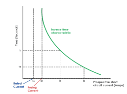
Fig 31 Time Current Characteristics of Fuse
Symbol MCB, MCCB, ELCB:
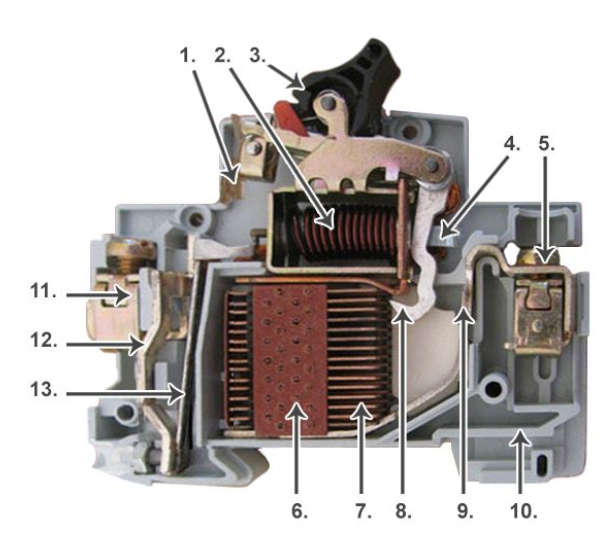
Fig 32 Symbol of Miniature Circuit breaker
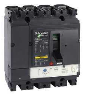
Fig 33 Symbol of Mounded case circuit breaker
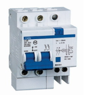
Fig 34 Symbol of Earth Leakage circuit breaker
Key takeaways:
Single Line Diagram:
In single line representation of substation, the electrical components such as power transformers, incoming and outgoing lines, bus-bars, switching and protecting equipments, are represented by standard symbols and their interconnections between them are shown by lines. Single line diagrams are useful in planning a substation layout.
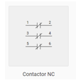
Single Line Symbol of Contactor:
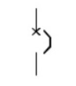
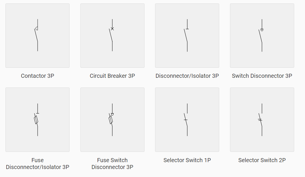
Single Line Symbol of Isolator:
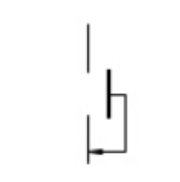
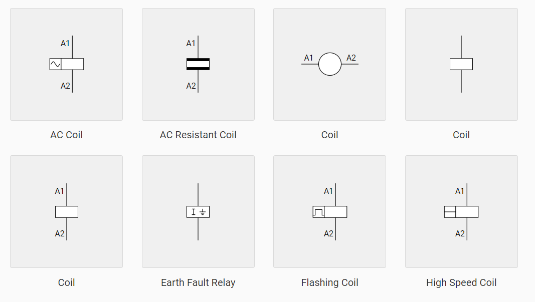
Single Line symbol of Relays:

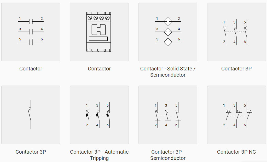
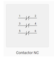
Single Line symbol of MPCB:
Key takeaways:
Electrical Safety
Electric equipment can pose a serious risk to workers, especially if mishandled or poorly maintained. Many electrical appliances have high voltage or high-power requirements, which further increase the risk.
Risk of electric shock
The main dangers associated with electricity are electric shock, fire and arc flash. An electric shock occurs when an individual becomes part of an electrical circuit and either contacts both wires of the electrical circuit, one wire of the energized circuit and ground, or a metal part energized by contact, occurs and conductor.
The severity and impact of electric shock depends on many factors, including the route through the body, the amount of electrical current, the length of exposure, and whether the skin is wet or dry. Water is an excellent electrical conductor, which makes it easier for current to flow in wet or wet skin.
The effects of shock can range from slight tingling to severe burns to cardiac arrest. The graph below shows the general relationship between the degree of injury and the amount of current in the 60-cycle hand-to-foot path of a 1-second impact. When reading this chart, keep in mind that most electrical circuits can deliver up to 20,000mA under normal conditions.
Current | Reaction |
1 Milliampere | Perception level |
5 Milliamperes | Slight shock felt; not painful but disturbing |
6-30 Milliamperes | Painful shock; “let-go” range |
50-150 Milliamperes | Extreme pain, respiratory arrest, severe muscular contraction |
1000-4,300 Milliamperes | Ventricular fibrillation |
10,000+ Milliamperes | Cardiac arrest, severe burns and probable death |
In addition to the risk of electric shock, sparks from electrical equipment can act as a source of flammable or explosive vapours.
Arc Flash
Dangerous arc flashes can occur in electrical equipment that has high enough energy to sustain the arc, regardless of voltage. Here are some places where this can happen:
In an arc flash accident, a large amount of concentrated radiant energy explodes outward from electrical equipment. The explosion produces pressure waves that can impair one's hearing, high-intensity flashes that can impair vision, and overheated gas spheres that can severely burn a worker's body and melt metal. I will.
Electrical Safety Related Work Practices
Only qualified workers trained to avoid electrical hazards are allowed to work in or near exposed energized parts. Safety-related work practices are electric shock or other injury caused by direct or indirect electrical contact when work is performed near or on equipment or circuits that are or may be energized. It is adopted to prevent. Certain safety-related work practices must be consistent with the nature and extent of the associated electrical hazard.
Qualified and Unqualified
There are two types of employees who may come into contact with electrical equipment in the workplace for the purposes of electrical safety-related work practices: qualified and unqualified. What is a qualified employee?
An unqualified employee is defined as a worker who has little or no training in electrical hazards. Unqualified persons should not be exposed to energized parts, but they should perform their work in a safe manner and provide the information and training they need to understand:
Charging units that may be exposed to employees should be turned off before or near them. Examples of increased or additional hazards include interruption of life support systems, deactivation of emergency alert systems, shutdown of ventilators in hazardous areas, or removal of lighting in areas. If there is no increased exposure to electrical burns or explosions from electric arcs, it is not necessary to power off the charging unit, which operates below 50 volts to ground.
Working on or near an energized circuit
Charging units that may be exposed to employees should be turned off before or near them. Examples of increased or additional hazards include interruption of life support systems, deactivation of emergency alert systems, shutdown of ventilators in hazardous areas, or removal of lighting in areas. If there is no increased exposure to electrical burns or explosions from electric arcs, it is not necessary to power off the charger that operates below 50 volts to ground.
Non-Energized Parts
Energized Parts
Employees should work in or near exposed energized parts if they come into direct contact with exposed charging parts, or if they use tools or materials, or if they work close enough to endanger the energized parts. Is considered to be. Only qualified personnel are allowed to work with unpowered (lockout / tagout) electrical circuit components or equipment. Qualified personnel can work safely in energized circuits and are familiar with special precautionary techniques, personal protective equipment, insulation and shielding materials, and proper use of insulation tools.
| ||||||||||||||||||
Overhead line
If you work near an overhead transmission line, you must turn off the transmission line and ground it or take other protective measures before starting construction. Protective measures such as protection, isolation, and insulation prevent the line from contacting any part of the body through or indirectly through conductive materials, tools, or equipment by qualified personnel. will do.
Unqualified persons working high up near overhead power lines may approach or handle conductive objects that may come into contact with or approach unprotected energized overhead power lines than the following distances: It cannot be done.
Voltage to Ground | Distance |
50kV or below | 10 feet |
Over 50kV | 10 feet (plus 4 in. for each 10kV over 50kV) |
Unqualified persons working on the ground near overhead power lines can send conductive or insulated objects that do not have the proper insulation rating to the unprotected, energized overhead transmission specified at the distances above. It cannot be brought close to the electric wire.
Qualified personnel working near overhead power lines, whether high or above ground, have approved insulating handles near exposed energized areas in the "Qualified Persons' Approach" in the table above. Without it, you will not be able to approach or bring in conductive objects a. ) If appropriate gloves are used, sleeves are used as needed, the associated voltage is rated and insulated from the energized part, or b.) If the energized part is insulated from everyone, or c. ) A person is insulated from all conductive objects at a different potential than the energized part.
Electrical Safety Protection Method
Use of Protective Equipment
Employees working in areas of potential electrical hazards should provide and use electrical protective equipment suitable for the body parts to be protected and the work to be performed. Protective equipment should be maintained in a safe and reliable condition and regularly inspected or tested as required by 29 CFR 1910.137, electrical protection equipment. If the dielectric strength of the protective equipment is damaged during use, the insulating material must be protected by covering it with leather or other suitable material. Non-conductive head protectors should be worn whenever there is a risk of electric shock or head injury due to contact with exposed energized parts. Eye protection should be worn if there is a risk of eye or face injury from electric arcs, flashes, or electrical splashes.
General Protective Equipment and Tools
Insulated tools and handling equipment should be employed by employees working near exposed energized conductors OR circuit components if the tools and / or equipment may inherit contact with conductors or components. Insulating materials for tools and equipment should be protected during a vulnerable area. If the fuse terminals are energized, you want to use a fuse processing device that's isolated from the circuit voltage to get rid of or install the fuse. All ropes and handlines used near exposed energized components must be non-conductive. Electric shock, burns, or other damage when working near exposed live parts that employees may are available contact with, or where dangerous electrical heat or arcs may occur. Protective shields, protective barriers, or insulating materials should be wont to protect employees from electrical injuries. If a normally sealed charging area is exposed for maintenance or repair, the parts should be shielded from contact with the charging area by unqualified personnel.
Alert Technique
Warning technology must be wont to warn and protect employees from the danger of electrical shock, burns, or failure of electrical equipment components. Safety signs, safety signs, or accident prevention tags should be used when necessary to alert employees to electrical hazards that would endanger them. Barricades should be utilized in combination with safety signs as required to stop or limit employee access to figure areas exposed to non-insulated, energized conductors OR circuit components. There is. don't use conductive barricades where they will pose a risk of contact. If signs or barricades don't provide sufficient warning and protection, personnel should be assigned to warn and protect employees.
Arc Flash Personal Protective Equipment
This personal protector provides protection after an arc flash accident and will be considered the last line of protection. the choice of the acceptable PPE for the task to be performed is predicated on the hazard category in NFPA 70E – 2004 and can be displayed on the labelled electrical panels and equipment.
The following table is provided as a fast reference. Workers should review all appropriate safety requirements before starting work.
Personal Protective Equipment Requirements for Arc Flash Protection
Category | Energy Level | PPE Requirements |
0 | ≤2 Cal/cm² | Non-melting or untreated natural fiber |
1 | 4 Cal/cm² | Fire Resistant (FR) shirt and pants |
2 | 8 Cal/cm² | Fire Resistant shirt and pants, cotton underwear |
3 | 25 Cal/cm² | Two layers Fire Resistant clothing, cotton underwear |
4 | 40 Cal/cm² | Fire Resistant shirt and pants, multilayer flash suit, cotton underwear. |
Face protection includes face shields and / or safety goggles. Hand protection includes leather on rubber for arc flash protection. Leather work boots of 4cal / cm² or more.
Outdoor Work and Extension Cords
Working outdoors
Extension Cord
Key Takeaways:
References:
1. S. L. Uppal and G. C. Garg, “Electrical Wiring, publishers, 2008
2. KB. Raina, “Electrical Design, Estimating & Costing”, New age International, 2007
3. S. Singh and RD. Singh, “Electrical estimating and costing", Dhanpat Ral and Co. 1997. Web site for IS Standards
4. H. Joshi, “Residential Commercial and Industrial System”, McGraw Hill Education, 2008