Unit 4
Super heterodyne Receivers
The shortcomings of TRF receivers is overcome by super heterodyne receiver

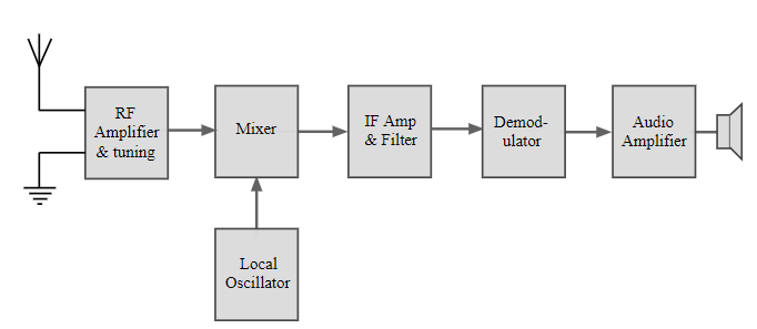
Fig.1: Superheterodyne receiver
RF tuning & amplification: This RF stage within the overall block diagram for the receiver provides initial tuning to remove the image signal. It also provides some amplification.
If the noise performance for the receiver is important, then this stage will be designed for optimum noise performance.
This RF amplifier circuit block will also increase the signal level so that the noise introduced by later stages is at a lower level in comparison to the wanted signal.
Mixer: Both the local oscillator and incoming signal enter this block within the super heterodyne receiver. The wanted signal is converted to the intermediate frequency.
IF amplifier & filter: This super heterodyne receiver block provides the majority of gain and selectivity. High performance filters like crystal filters are used although LC or ceramic filters may be used within domestic radios.
Demodulator: The super heterodyne receiver block diagram only shows one demodulator, but in reality radios may have one or more demodulators dependent upon the type of signals being receiver.
Audio Amplifier
Once demodulated, the recovered audio is applied to an audio amplifier block has to be amplified to the required level for loudspeakers or headphones. Alternatively, the recovered modulation is used for other applications where it is processed in the required way by a specific purpose.
Operation
- The signals enter the receiver from the antenna and are applied to the RF amplifier where they are tuned to remove the image signal as well as reduce the general level of unwanted signals on other frequencies that are not required.
- The signals are applied to the mixer along with the local oscillator where the wanted signal is converted down to the intermediate frequency. Here significant levels of amplification are applied and signals are filtered.
- This filtering selects signals on one channel against those on the next. It is much larger than that employed in the front end. The advantage of the IF filter as opposed to RF filtering is that the filter can be designed for a fixed frequency. This allows for much better tuning. Variable filters are never able to provide the same level of selectivity that can be provided by fixed frequency ones.
- Once filtered the next block in the super heterodyne receiver is the demodulator. This could be for amplitude modulation, single sideband, frequency modulation, or indeed any form of modulation. It is also possible to switch different demodulators according to the mode received.
- The final element in the super heterodyne receiver block diagram is shown as an audio amplifier, this could be any form of circuit block that is used to process or amplified the demodulated signal.
Alignment and tracking of the Receiver
- The RF and local oscillator tuning capacitors are mechanically coupled on the same shaft and have the same capacitance/rotation law.
- As the shaft is rotated both circuits vary in frequency.
- When the local oscillator is set such that its difference from the signal frequency is equal to IF then any mis-tuning results in a loss of signal strength, an increase in adjacent channel interference and possibly between-channel cross-modulation.
- The tuning capacitor can be swept over the frequency band for error checks.

Fig.2: Superheterodyne receiver circuit
- RF mis-tuning is described as an 'error' and is measured in kHz. It is measured as a fraction of the wanted signal frequency. If the fractional error exceeds approximately 1/Q of the RF tuned circuit then best use of RF signal circuit selectivity is not being made.
- Within a particular waveband there are three frequencies of zero-error. Optimum performance is obtained when the errors at the four frequencies of greatest error all have similar magnitudes.
An intermediate frequency is present between the baseband frequency and the carrier frequency. IF circuitry can be incorporated for both transmitters and receivers, but the benefits of IF techniques are more relevant to receivers.
Advantages:
It has the ability to design a receiver in which more of the circuitry can be designed for one unchanging frequency band.
It minimizes high frequency processing.
It has lower Q.
To mitigate the effects of the image spectrum, heterodyne receivers use image-reject filters. They are placed before the mixer and the image spectrum is suppressed before the mixer shifts it to the intermediate frequency. This is an effective solution, but there are two complications.
Trade offs
If we increase the intermediate frequency too much, the difficulties created by the higher IF may outweigh the benefits of improved image rejection. Thus, image-rejection filtering entails a fundamental trade-off between image suppression and the desire to maintain a lower intermediate frequency.
Integration
Image rejection is typically accomplished by means of a filter that is not incorporated into an integrated circuit. In other words, image-reject filters consume PCB area and design time, and in the context of modern electronics, both of these resources are valuable and in short supply.

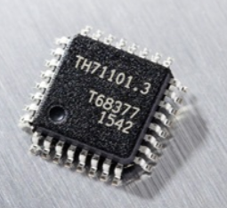
Fig.3: Superheterodyne receiver IC
References:
- “Electronic communication system”, by Kennedy, TMH
- “Communication system”, by haykin wiley
- “Communication system”, by bruce carison, TMH
- “Modern digital and analog communication”, B.P. LATHI, Oxford