UNIT- 5
Principles of Pipelining and Vector processing
- A program consists of several numbers of instructions.
- These instructions may be executed in the following two ways-
|
Figure 1 – Execution of instructions
- Non-Pipelined Execution
- Pipelined Execution
1. Non-Pipelined Execution-
In non-pipelined architecture,
- All the instructions of a program are executed sequentially one after the other.
- A new instruction executes only after the previous instruction has executed completely.
- This style of executing the instructions is highly inefficient.
Example-
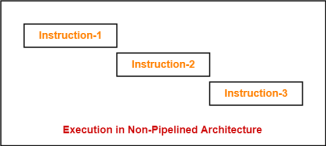
Consider a program consisting of three instructions.
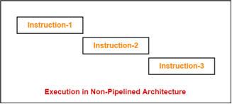
In a non-pipelined architecture, these instructions execute one after the other as-
|
Figure 2 – Example
If time taken for executing one instruction = t, then- Time taken for executing ‘n’ instructions = n x t |
2. Pipelined Execution-
In pipelined architecture,
- Multiple instructions are executed parallely.
- This style of executing the instructions is highly efficient.
Instruction Pipelining-
Instruction pipelining is a technique that implements a form of parallelism called as instruction level parallelism within a single processor. |
A pipelined processor does not wait until the previous instruction has executed completely.
Rather, it fetches the next instruction and begins its execution.
Pipelined Architecture-
In pipelined architecture,
- The hardware of the CPU is split up into several functional units.
- Each functional unit performs a dedicated task.
- The number of functional units may vary from processor to processor.
- These functional units are called as stages of the pipeline.
- Control unit manages all the stages using control signals.
- There is a register associated with each stage that holds the data.
- There is a global clock that synchronizes the working of all the stages.
- At the beginning of each clock cycle, each stage takes the input from its register.
- Each stage then processes the data and feed its output to the register of the next stage.
Four-Stage Pipeline-
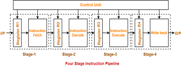
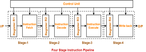
In four stage pipelined architecture, the execution of each instruction is completed in following 4 stages-
- Instruction fetch (IF)
- Instruction decode (ID)
- Instruction Execute (IE)
- Write back (WB)
To implement four stage pipeline,
- The hardware of the CPU is divided into four functional units.
- Each functional unit performs a dedicated task.
|
Figure 3 – Four stage instruction pipeline
Stage-01:
At stage-01,
- First functional unit performs instruction fetch.
- It fetches the instruction to be executed.
Stage-02:
At stage-02,
- Second functional unit performs instruction decode.
- It decodes the instruction to be executed.
Stage-03:
At stage-03,
- Third functional unit performs instruction execution.
- It executes the instruction.
Stage-04:
At stage-04,
- Fourth functional unit performs write back.
- It writes back the result so obtained after executing the instruction.
Execution-
In pipelined architecture,
- Instructions of the program execute parallely.
- When one instruction goes from nth stage to (n+1)th stage, another instruction goes from (n-1)th stage to nth stage.
Phase-Time Diagram-
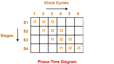
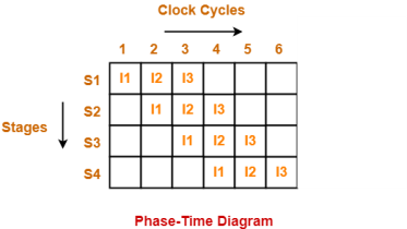
- Phase-time diagram shows the execution of instructions in the pipelined architecture.
- The following diagram shows the execution of three instructions in four stage pipeline architecture.
|
Figure 4 – Phase time diagram
Time taken to execute three instructions in four stage pipelined architecture = 6 clock cycles.
NOTE-
In non-pipelined architecture,
Time taken to execute three instructions would be
= 3 x Time taken to execute one instruction
= 3 x 4 clock cycles
= 12 clock cycles
Clearly, pipelined execution of instructions is far more efficient than non-pipelined execution.
Key takeaways
- A program consists of several numbers of instructions.
- These instructions may be executed in the following two ways-
|
3. Non-Pipelined Execution
4. Pipelined Execution
To improve the performance of a CPU we have two options:
1) Improve the hardware by introducing faster circuits.
2) Arrange the hardware such that more than one operation can be performed at the same time.Since, there is a limit on the speed of hardware and the cost of faster circuits is quite high, we have to adopt the 2nd option.
Pipelining : Pipelining is a process of arrangement of hardware elements of the CPU such that its overall performance is increased. Simultaneous execution of more than one instruction takes place in a pipelined processor.
Let us see a real life example that works on the concept of pipelined operation. Consider a water bottle packaging plant. Let there be 3 stages that a bottle should pass through, Inserting the bottle(I), Filling water in the bottle(F), and Sealing the bottle(S). Let us consider these stages as stage 1, stage 2 and stage 3 respectively. Let each stage take 1 minute to complete its operation.
Now, in a non pipelined operation, a bottle is first inserted in the plant, after 1 minute it is moved to stage 2 where water is filled. Now, in stage 1 nothing is happening. Similarly, when the bottle moves to stage 3, both stage 1 and stage 2 are idle. But in pipelined operation, when the bottle is in stage 2, another bottle can be loaded at stage 1. Similarly, when the bottle is in stage 3, there can be one bottle each in stage 1 and stage 2. So, after each minute, we get a new bottle at the end of stage 3. Hence, the average time taken to manufacture 1 bottle is :
Without pipelining = 9/3 minutes = 3m
I F S | | | | | | | | | I F S | | | | | | | | | I F S (9 minutes) With pipelining = 5/3 minutes = 1.67m I F S | | | I F S | | | I F S (5 minutes) Thus, pipelined operation increases the efficiency of a system. |
Design of a basic pipeline
- In a pipelined processor, a pipeline has two ends, the input end and the output end. Between these ends, there are multiple stages/segments such that output of one stage is connected to input of next stage and each stage performs a specific operation.
- Interface registers are used to hold the intermediate output between two stages. These interface registers are also called latch or buffer.
- All the stages in the pipeline along with the interface registers are controlled by a common clock.
Execution in a pipelined processor
Execution sequence of instructions in a pipelined processor can be visualized using a space-time diagram. For example, consider a processor having 4 stages and let there be 2 instructions to be executed. We can visualize the execution sequence through the following space-time diagrams:
Non overlapped execution:
Stage / Cycle | 1 | 2 | 3 | 4 | 5 | 6 | 7 | 8 |
S1 | I1 |
|
|
| I2 |
|
|
|
S2 |
| I1 |
|
|
| I2 |
|
|
S3 |
|
| I1 |
|
|
| I2 |
|
S4 |
|
|
| I1 |
|
|
| I2 |
Total time = 8 Cycle
Overlapped execution:
Stage / Cycle | 1 | 2 | 3 | 4 | 5 |
S1 | I1 | I2 |
|
|
|
S2 |
| I1 | I2 |
|
|
S3 |
|
| I1 | I2 |
|
S4 |
|
|
| I1 | I2 |
Total time = 5 Cycle
Pipeline Stages
RISC processor has 5 stage instruction pipeline to execute all the instructions in the RISC instruction set. Following are the 5 stages of RISC pipeline with their respective operations:
- Stage 1 (Instruction Fetch)
In this stage the CPU reads instructions from the address in the memory whose value is present in the program counter. - Stage 2 (Instruction Decode)
In this stage, instruction is decoded and the register file is accessed to get the values from the registers used in the instruction. - Stage 3 (Instruction Execute)
In this stage, ALU operations are performed. - Stage 4 (Memory Access)
In this stage, memory operands are read and written from/to the memory that is present in the instruction. - Stage 5 (Write Back)
In this stage, computed/fetched value is written back to the register present in the instructions.
Performance of a pipelined processor
Consider a ‘k’ segment pipeline with clock cycle time as ‘Tp’. Let there be ‘n’ tasks to be completed in the pipelined processor. Now, the first instruction is going to take ‘k’ cycles to come out of the pipeline but the other ‘n – 1’ instructions will take only ‘1’ cycle each, i.e, a total of ‘n – 1’ cycles. So, time taken to execute ‘n’ instructions in a pipelined processor:
ETpipeline = k + n – 1 cycles = (k + n – 1) Tp In the same case, for a non-pipelined processor, execution time of ‘n’ instructions will be: ETnon-pipeline = n * k * Tp So, speedup (S) of the pipelined processor over non-pipelined processor, when ‘n’ tasks are executed on the same processor is: S = Performance of pipelined processor / Performance of Non-pipelined processor As the performance of a processor is inversely proportional to the execution time, we have, S = ETnon-pipeline / ETpipeline => S = [n * k * Tp] / [(k + n – 1) * Tp] S = [n * k] / [k + n – 1] When the number of tasks ‘n’ are significantly larger than k, that is, n >> k S = n * k / n S = k |
where ‘k’ are the number of stages in the pipeline.
Also, Efficiency = Given speed up / Max speed up = S / Smax So, Efficiency = S / k Throughput = Number of instructions / Total time to complete the instructions So, Throughput = n / (k + n – 1) * Tp Note: The cycles per instruction (CPI) value of an ideal pipelined processor is 1 |
Key takeaway
Pipelining : Pipelining is a process of arrangement of hardware elements of the CPU such that its overall performance is increased. Simultaneous execution of more than one instruction takes place in a pipelined processor.
Let us see a real life example that works on the concept of pipelined operation. Consider a water bottle packaging plant. Let there be 3 stages that a bottle should pass through, Inserting the bottle(I), Filling water in the bottle(F), and Sealing the bottle(S). Let us consider these stages as stage 1, stage 2 and stage 3 respectively. Let each stage take 1 minute to complete its operation.
Now, in a non pipelined operation, a bottle is first inserted in the plant, after 1 minute it is moved to stage 2 where water is filled. Now, in stage 1 nothing is happening. Similarly, when the bottle moves to stage 3, both stage 1 and stage 2 are idle. But in pipelined operation, when the bottle is in stage 2, another bottle can be loaded at stage 1. Similarly, when the bottle is in stage 3, there can be one bottle each in stage 1 and stage 2.
Representing and storing numbers were the basic of operation of the computers of earlier times. The real go came when computation, manipulating numbers like adding, multiplying came into picture. These operations are handled by computer’s arithmetic logic unit (ALU). The ALU is the mathematical brain of a computer. The first ALU was INTEL 74181 implemented as a 7400 series is a TTL integrated circuit which was released in 1970.
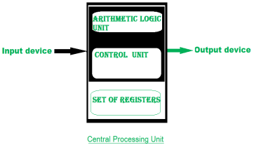
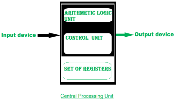
The ALU is a digital circuit that provides arithmetic and logic operation. It is the fundamental building block of central processing unit of a computer. A modern CPU has very powerful ALU and it is complex in design. In addition to ALU modern CPU contains control unit and set of registers. Most of the operations are performed by one or more ALU’s, which load data from input register. Registers are a small amount of storage available to CPU. These registers can be accessed very fast. The control unit tells ALU what operation to perform on the available data. After calculation/manipulation the ALU stores the output in an output register.
|
Figure 5 – Central processing unit
The CPU can be divided into two section: data section and control section. The DATA section is also known as data path.
BUS:
In early computers “BUS” were parallel electrical wires with multiple hardware connections. Therefore a bus is communication system that transfers data between component inside a computer, or between computers. It includes hardware components like wires, optical fibers, etc and software, including communication protocols. The Registers, ALU and the interconnecting BUS are collectively referred as data path.
Types of bus are:
- Address bus: The buses which are used to carry address.
- Data bus: The buses which are used to carry data.
- Control bus: If the bus is carrying control signals .
- Power bus: If it is carrying clock pulse, power signals it is known as power bus, and so on.
The bus can be dedicated, i.e., it can be used for a single purpose or it can be multiplexed, i.e., it can be used for multiple purpose. When we would have different kinds of buses, different types of bus organisation will take place.
- Program Counter –
A program counter (PC) is a CPU register in the computer processor which has the address of the next instruction to be executed from memory. As each instruction gets fetched, the program counter increases its stored value by 1. It is a digital counter needed for faster execution of tasks as well as for tracking the current execution point. - Instruction Register –
In computing, an instruction register (IR) is the part of a CPU’s control unit that holds the instruction currently being executed or decoded. An instruction register is the part of a CPU’s control unit that holds the instruction currently being executed or decoded. Instruction register specifically holds the instruction and provides it to instruction decoder circuit. - Memory Address Register –
The Memory Address Register (MAR) is the CPU register that either stores the memory address from which data will be fetched from the CPU, or the address to which data will be sent and stored. It is a temporary storage component in the CPU(central processing unit) which temporarily stores the address (location) of the data sent by the memory unit until the instruction for the particular data is executed. - Memory Data Register –
The memory data register (MDR) is the register in a computer’s processor, or central processing unit, CPU, that stores the data being transferred to and from the immediate access storage. Mmemory data register (MDR) is also known as memory buffer register (MBR). - General Purpose Register –
General purpose registers are used to store temporary data within the microprocessor. It is a multipurpose register. They can be used either by programmer or by a user.
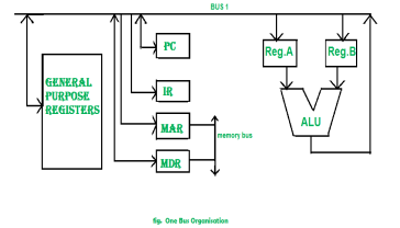
One Bus organization –
|
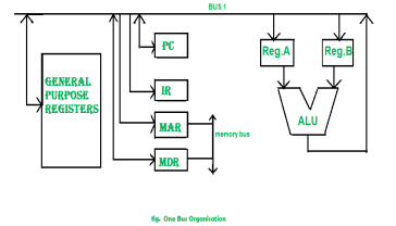
Figure 6 – One bus organisation
In one bus organisation, a single bus is used for multiple purpose. A set of general purpose register, program counter, instruction register, memory address register(MAR), memory data register(MDR) are connected with the single bus. Memory read/write can be done with MAR and MDR. The program counter points to the memory location from where the next instruction is to be fetched. Instruction register is that very register will hold the copy of the current instruction. In case of one bus organisation, at a time only one operand can be read from the bus.
As a result of that, if the requirement is to read two operand for the operation then read operation need to be carried twice. So that’s why it is making the process little longer. One of the advantage of one bus organisation is that, it is one of the simplest and also this is very cheap to implement. At the same time a disadvantage lies that it has only one bus and this “one bus” is accessed by all general purpose registers, program counter, instruction register, MAR, MDR making each and every operation sequential. No one recommend this architecture now-a-days.
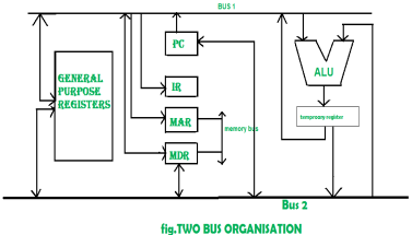
Two Bus organizatrion –
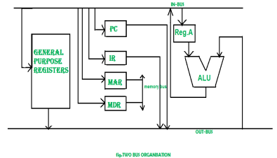
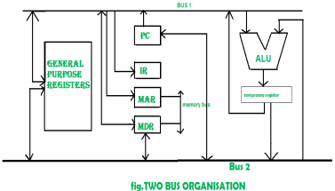
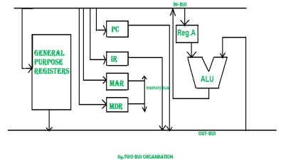
Two overcome the disadvantage of one bus organisation an another architecture was developed known as two bus organisation. In two bus organisation there are two buses. The general purpose register can read/write from both the buses. In this case, two operands can be fetched at the same time because of the two buses. One of bus fetch operand for ALU and another bus fetch for register. The situation arrises when both buses are busy fetching operands, output can be stored in temporary register and when the buses are free, particular output can be dumped on the buses.
There are two versions of two bus organisation, i.e., in-bus and out-bus.From in-bus the general purpose register can read data and to the out bus the general purpose registers can write data.Here buses gets dedicated.
|
Figure 7 – Two bus organisation |
|
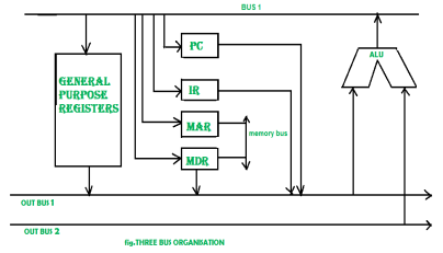
Three Bus organizatrion –
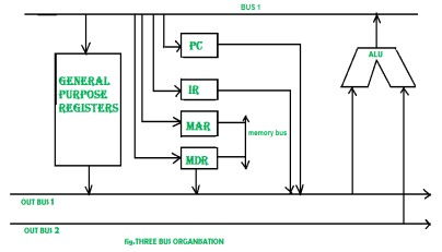
In three bus organisation we have three bus, OUT bus1, OUT bus2 and a IN bus. From the out buses we can get the operand which can come from general purpose register and evaluated in ALU and the output is dropped on In Bus so it can be sent to respective registers.This implementation is a bit complex but faster in nature because in parallel two operands can flow into ALU and out of ALU. It was developed to overcome the “busy waiting” problem of two bus organisation. In this structure after execution, the output can be dropped on the bus without waiting because of presence of an extra bus. The structure is given below in the figure.
|
Figure 8 – Three bus organisation
The main advantages of multiple bus organisations over single bus are as given below.
- Increase in size of the registers.
- Reduction in the number of cycles for execution.
- Increases the speed of execution or we can say faster execution.
Key takeaway
Representing and storing numbers were the basic of operation of the computers of earlier times. The real go came when computation, manipulating numbers like adding, multiplying came into picture. These operations are handled by computer’s arithmetic logic unit (ALU). The ALU is the mathematical brain of a computer. The first ALU was INTEL 74181 implemented as a 7400 series is a TTL integrated circuit which was released in 1970.
The ALU is a digital circuit that provides arithmetic and logic operation. It is the fundamental building block of central processing unit of a computer. A modern CPU has very powerful ALU and it is complex in design. In addition to ALU modern CPU contains control unit and set of registers. Most of the operations are performed by one or more ALU’s, which load data from input register. Registers are a small amount of storage available to CPU. These registers can be accessed very fast. The control unit tells ALU what operation to perform on the available data. After calculation/manipulation the ALU stores the output in an output register.
Data Parallelism means concurrent execution of the same task on each multiple computing core.
Let’s take an example, summing the contents of an array of size N. For a single-core system, one thread would simply sum the elements [0] . . . [N − 1]. For a dual-core system, however, thread A, running on core 0, could sum the elements [0] . . . [N/2 − 1] and while thread B, running on core 1, could sum the elements [N/2] . . . [N − 1]. So the Two threads would be running in parallel on separate computing cores.
Task Parallelism
Task Parallelism means concurrent execution of the different task on multiple computing cores.
Consider again our example above, an example of task parallelism might involve two threads, each performing a unique statistical operation on the array of elements. Again The threads are operating in parallel on separate computing cores, but each is performing a unique operation.
Bit-level parallelism
Bit-level parallelism is a form of parallel computing which is based on increasing processor word size. In this type of parallelism, with increasing the word size reduces the number of instructions the processor must execute in order to perform an operation on variables whose sizes are greater than the length of the word.
E.g., consider a case where an 8-bit processor must add two 16-bit integers. First the 8 lower-order bits from each integer were must added by processor, then add the 8 higher-order bits, and then two instructions to complete a single operation. A processor with 16- bit would be able to complete the operation with single instruction.
Instruction-level parallelism
Instruction-level parallelism means the simultaneous execution of multiple instructions from a program. While pipelining is a form of ILP, we must exploit it to achieve parallel execution of the instructions in the instruction stream.
Example
for (i=1; i<=100; i= i+1) y[i] = y[i] + x[i]; |
This is a parallel loop. Every iteration of the loop can overlap with any other iteration, although within each loop iteration there is little opportunity for overlap.
Key takeaways
- Data Parallelism means concurrent execution of the same task on each multiple computing core.
- Let’s take an example, summing the contents of an array of size N. For a single-core system, one thread would simply sum the elements [0] . . . [N − 1]. For a dual-core system, however, thread A, running on core 0, could sum the elements [0] . . . [N/2 − 1] and while thread B, running on core 1, could sum the elements [N/2] . . . [N − 1]. So the Two threads would be running in parallel on separate computing cores.
Introduction
Have you ever visited an industrial plant and see the assembly lines over there? How a product passes through the assembly line and while passing it is worked on, at different phases simultaneously. For example, take a car manufacturing plant. At the first stage, the automobile chassis is prepared, in the next stage workers add body to the chassis, further, the engine is installed, then painting work is done and so on.
The group of workers after working on the chassis of the first car don’t sit idle. They start working on the chassis of the next car. And the next group take the chassis of the car and add body to it. The same thing is repeated at every stage, after finishing the work on the current car body they take on next car body which is the output of the previous stage.
Here, though the first car is completed in several hours or days, due to the assembly line arrangement it becomes possible to have a new car at the end of an assembly line in every clock cycle.
Similarly, the concept of pipelining works. The output of the first pipeline becomes the input for the next pipeline. It is like a set of data processing unit connected in series to utilize processor up to its maximum.
An instruction in a process is divided into 5 subtasks likely,
|
- In the first subtask, the instruction is fetched.
- The fetched instruction is decoded in the second stage.
- In the third stage, the operands of the instruction are fetched.
- In the fourth, arithmetic and logical operation are performed on the operands to execute the instruction.
- In the fifth stage, the result is stored in memory.
Now, understanding the division of the instruction into subtasks. Let us understand, how the n number of instructions in a process, are pipelined.
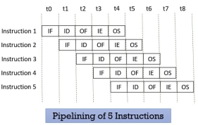
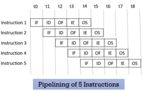
Look at the figure below the 5 instructions are pipelined. The first instruction gets completed in 5 clock cycle. After the completion of first instruction, in every new clock cycle, a new instruction completes its execution.
|
Figure 9 – Pipelining of 5 Instructions
Observe that when the Instruction fetch operation of the first instruction is completed in the next clock cycle the instruction fetch of second instruction gets started. This way the hardware never sits idle it is always busy in performing some or other operation. But, no two instructions can execute their same stage at the same clock cycle.
Types of Pipelining
In 1977 Handler and Ramamoorthy classified pipeline processors depending on their functionality.
1. Arithmetic Pipelining
It is designed to perform high-speed floating-point addition, multiplication and division. Here, the multiple arithmetic logic units are built in the system to perform the parallel arithmetic computation in various data format. Examples of the arithmetic pipelined processor are Star-100, TI-ASC, Cray-1, Cyber-205.
2. Instruction Pipelining
Here, the number of instruction are pipelined and the execution of current instruction is overlapped by the execution of the subsequent instruction. It is also called instruction lookahead.
3. Processor Pipelining
Here, the processors are pipelined to process the same data stream. The data stream is processed by the first processor and the result is stored in the memory block. The result in the memory block is accessed by the second processor. The second processor reprocesses the result obtained by the first processor and the passes the refined result to the third processor and so on.
4. Unifunction Vs. Multifunction Pipelining
The pipeline performing the precise function every time is unifunctional pipeline. On the other hand, the pipeline performing multiple functions at a different time or multiple functions at the same time is multifunction pipeline.
5. Static vs Dynamic Pipelining
The static pipeline performs a fixed-function each time. The static pipeline is unifunctional. The static pipeline executes the same type of instructions continuously. Frequent change in the type of instruction may vary the performance of the pipelining.
Dynamic pipeline performs several functions simultaneously. It is a multifunction pipelining.
6. Scalar vs Vector Pipelining
Scalar pipelining processes the instructions with scalar operands. The vector pipeline processes the instruction with vector operands.
Pipelining Hazards
Whenever a pipeline has to stall due to some reason it is called pipeline hazards. Below we have discussed four pipelining hazards.
1. Data Dependency
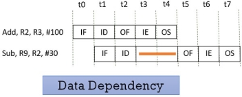
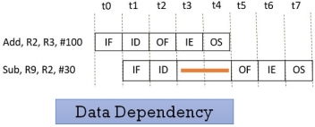
Consider the following two instructions and their pipeline execution:
|
Figure 10 – Data Dependency
In the figure above, you can see that result of the Add instruction is stored in the register R2 and we know that the final result is stored at the end of the execution of the instruction which will happen at the clock cycle t4.
But the Sub instruction need the value of the register R2 at the cycle t3. So the Sub instruction has to stall two clock cycles. If it doesn’t stall it will generate an incorrect result. Thus depending of one instruction on other instruction for data is data dependency.
2. Memory Delay
When an instruction or data is required, it is first searched in the cache memory if not found then it is a cache miss. The data is further searched in the memory which may take ten or more cycles. So, for that number of cycle the pipeline has to stall and this is a memory delay hazard. The cache miss, also results in the delay of all the subsequent instructions.
3. Branch Delay
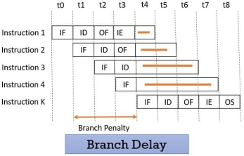
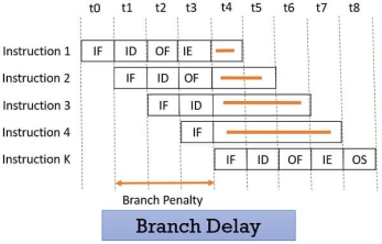
Suppose the four instructions are pipelined I1, I2, I3, I4 in a sequence. The instruction I1 is a branch instruction and its target instruction is Ik. Now, processing starts and instruction I1 is fetched, decoded and the target address is computed at the 4th stage in cycle t3.
But till then the instructions I2, I3, I4 are fetched in cycle 1, 2 & 3 before the target branch address is computed. As I1 is found to be a branch instruction, the instructions I2, I3, I4 has to be discarded because the instruction Ik has to be processed next to I1. So, this delay of three cycles 1, 2, 3 is a branch delay.
|
Figure 11 – Branch Delay
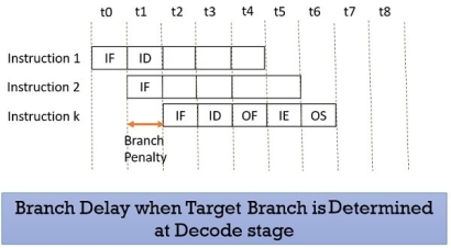
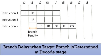
Prefetching the target branch address will reduce the branch delay. Like if the target branch is identified at the decode stage then the branch delay will reduce to 1 clock cycle.
|
Figure 12 – Branch delay when target branch is determined at decode stage
4. Resource Limitation
If the two instructions request for accessing the same resource in the same clock cycle, then one of the instruction has to stall and let the other instruction to use the resource. This stalling is due to resource limitation. However, it can be prevented by adding more hardware.
Advantages
- Pipelining improves the throughput of the system.
- In every clock cycle, a new instruction finishes its execution.
- Allow multiple instructions to be executed concurrently.
Key Takeaways
- Pipelining divides the instruction in 5 stages instruction fetch, instruction decode, operand fetch, instruction execution and operand store.
- The pipeline allows the execution of multiple instructions concurrently with the limitation that no two instructions would be executed at the same stage in the same clock cycle.
- All the stages must process at equal speed else the slowest stage would become the bottleneck.
- Whenever a pipeline has to stall for any reason it is a pipeline hazard.
- Have you ever visited an industrial plant and see the assembly lines over there? How a product passes through the assembly line and while passing it is worked on, at different phases simultaneously. For example, take a car manufacturing plant. At the first stage, the automobile chassis is prepared, in the next stage workers add body to the chassis, further, the engine is installed, then painting work is done and so on.
- The group of workers after working on the chassis of the first car don’t sit idle. They start working on the chassis of the next car. And the next group take the chassis of the car and add body to it. The same thing is repeated at every stage, after finishing the work on the current car body they take on next car body which is the output of the previous stage.
- Here, though the first car is completed in several hours or days, due to the assembly line arrangement it becomes possible to have a new car at the end of an assembly line in every clock cycle.
- Similarly, the concept of pipelining works. The output of the first pipeline becomes the input for the next pipeline. It is like a set of data processing unit connected in series to utilize processor up to its maximum.
Introduction
We need computers that can solve mathematical problems for us which include, arithmetic operations on the large arrays of integers or floating-point numbers quickly. The general-purpose computer would use loops to operate on an array of integers or floating-point numbers. But, for large array using loop would cause overhead to the processor.
To avoid the overhead of processing loops and fasten the computation, some kind of parallelism must be introduced. Vector processing operates on the entire array in just one operation i.e. it operates on elements of the array in parallel. But, vector processing is possible only if the operations performed in parallel are independent.
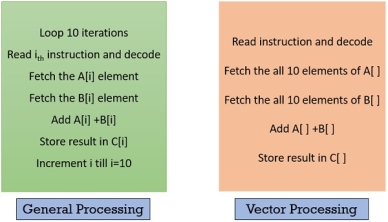
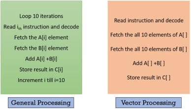
Look at the figure below, and compare the vector processing with the general computer processing, you will notice the difference. Below, instructions in both the blocks are set to add two arrays and store the result in the third array. Vector processing adds both the array in parallel by avoiding the use of the loop.
|
Figure 13 – General processing , Vector processing
Operating on multiple data in just one instruction is also called Single Instruction Multiple Data (SIMD) or they are also termed as Vector instructions. Now, the data for vector instruction are stored in vector registers.
Each vector register is capable of storing several data elements at a time. These several data elements in a vector register is termed as a vector operand. So, if there are n number of elements in a vector operand then n is the length of the vector.
Supercomputers were evolved to deal with billions of floating-point operations/second. Supercomputer optimizes numerical computations (vector computations).
But, along with vector processing supercomputers are also capable of doing scalar processing. Later, Array processor was introduced which particularly deals with vector processing, they do not indulge in scalar processing.
Characteristics of Vector Processing
Each element of the vector operand is a scalar quantity which can either be an integer, floating-point number, logical value or a character. Below we have classified the vector instructions in four types.
Here, V is representing the vector operands and S represents the scalar operands. In the figure below, O1 and O2 are the unary operations and O3 and O4 are the binary operations.
Most of the vector instructions are pipelined as vector instruction performs the same operation on the different data sets repeatedly. Now, the pipelining has start-up delay, so longer vectors would perform better here.
The pipelined vector processors can be classified into two types based on from where the operand is being fetched for vector processing. The two architectural classifications are Memory-to-Memory and Register-to-Register.
In Memory-to-Memory vector processor the operands for instruction, the intermediate result and the final result all these are retrieved from the main memory. TI-ASC, CDC STAR-100, and Cyber-205 use memory-to-memory format for vector instructions.
In Register-to-Register vector processor the source operands for instruction, the intermediate result, and the final result all are retrieved from vector or scalar registers. Cray-1 and Fujitsu VP-200 use register-to-register format for vector instructions.
Vector Instruction
A vector instruction has the following fields:
1. Operation Code
Operation code indicates the operation that has to be performed in the given instruction. It decides the functional unit for the specified operation or reconfigures the multifunction unit.
2. Base Address
Base address field refers to the memory location from where the operands are to be fetched or to where the result has to be stored. The base address is found in the memory reference instructions. In the vector instruction, the operand and the result both are stored in the vector registers. Here, the base address refers to the designated vector register.
3. Address Increment
A vector operand has several data elements and address increment specifies the address of the next element in the operand. Some computer stores the data element consecutively in main memory for which the increment is always 1. But, some computers that do not store the data elements consecutively requires the variable address increment.
4. Address Offset
Address Offset is always specified related to the base address. The effective memory address is calculated using the address offset.
5. Vector Length
Vector length specifies the number of elements in a vector operand. It identifies the termination of a vector instruction.
Improving Performance
In vector processing, we come across two overheads setup time and flushing time. When the vector processing is pipelined, the time required to route the vector operands to the functional unit is called Set up time. Flushing time is a time duration that a vector instruction takes right from its decoding until its first result is out from the pipeline.
The vector length also affects the efficiency of processing as the longer vector length would cause overhead of subdividing the long vector for processing.
For obtaining the better performance the optimized object code must be produced in order to utilize pipeline resources to its maximum.
1. Improving the vector instruction
We can improve the vector instruction by reducing the memory access, and maximize resource utilization.
2. Integrate the scalar instruction
The scalar instruction of the same type must be integrated as a batch. As it will reduce the overhead of reconfiguring the pipeline again and again.
3. Algorithm
Choose the algorithm that would work faster for vector pipelined processing.
4. Vectorizing Compiler
A vectorizing compiler must regenerate the parallelism by using the higher-level programming language. In advance programming, the four-stage are identified in the development of the parallelism. Those are
- Parallel Algorithm(A)
- High-level Language(L)
- Efficient object code(O)
- Target machine code (M)
You can see a parameter in the parenthesis at each stage which denotes the degree of parallelism. In the ideal situation, the parameters are expected in the order A≥L≥O≥M.
Key Takeaways
- Computers having vector instruction are vector processors.
- Vector processor have the vector instructions which operates on the large array of integer or floating-point numbers or logical values or characters, all elements in parallel. It is called vectorization.
- Vectorization is possible only if the operation performed in parallel are independent of each other.
- Operands of vector instruction are stored in the vector register. A vector register stores several data elements at a time which is called vector operand.
- A vector operand has several scalar data elements.
- A vector instruction needs to perform the same operation on the different data set. Hence, vector processors have a pipelined structure.
- Vector processing ignores the overhead caused due to the loops while operating on an array.
- We need computers that can solve mathematical problems for us which include, arithmetic operations on the large arrays of integers or floating-point numbers quickly. The general-purpose computer would use loops to operate on an array of integers or floating-point numbers. But, for large array using loop would cause overhead to the processor.
- To avoid the overhead of processing loops and fasten the computation, some kind of parallelism must be introduced. Vector processing operates on the entire array in just one operation i.e. it operates on elements of the array in parallel. But, vector processing is possible only if the operations performed in parallel are independent.
Reference
1 Computer system architecture by M. Morris Mano
2 Computer Architecture and parallel processing by Kai Hwang, Briggs, McGraw
3 Hill
4 Computer Architecture by Carter, Tata McGraw Hill.
5 Computer System Organization and Architecture by John D. Carpinelli, Pearson Education

