UNIT - 3
Input-Output Organization
All types of computers follow the same basic logical structure and perform the following five basic operations for converting raw input data into information useful to their users.
S.No. | Operation | Description |
1 | Take Input | The process of entering data and instructions into the computer system. |
2 | Store Data | Saving data and instructions so that they are available for processing as and when required. |
3 | Processing Data | Performing arithmetic, and logical operations on data in order to convert them into useful information. |
4 | Output Information | The process of producing useful information or results for the user, such as a printed report or visual display. |
5 | Control the workflow | Directs the manner and sequence in which all of the above operations are performed. |
|
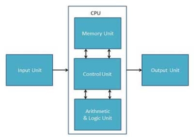
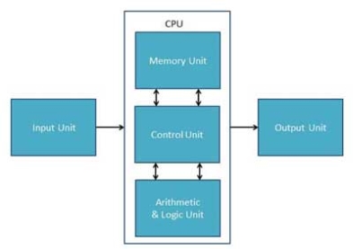
Figure 1 - CPU
Input Unit
This unit contains devices with the help of which we enter data into the computer. This unit creates a link between the user and the computer. The input devices translate the information into a form understandable by the computer.
CPU (Central Processing Unit)
CPU is considered as the brain of the computer. CPU performs all types of data processing operations. It stores data, intermediate results, and instructions (program). It controls the operation of all parts of the computer.
CPU itself has the following three components −
- ALU (Arithmetic Logic Unit)
- Memory Unit
- Control Unit
Output Unit
The output unit consists of devices with the help of which we get the information from the computer. This unit is a link between the computer and the users. Output devices translate the computer's output into a form understandable by the users.
Computer - Input Devices
Following are some of the important input devices which are used in a computer
- Keyboard
- Mouse
- Joy Stick
- Light pen
- Track Ball
- Scanner
- Graphic Tablet
- Microphone
- Magnetic Ink Card Reader(MICR)
- Optical Character Reader(OCR)
- Bar Code Reader
- Optical Mark Reader(OMR)
Keyboard
Keyboard is the most common and very popular input device which helps to input data to the computer. The layout of the keyboard is like that of traditional typewriter, although there are some additional keys provided for performing additional functions.
Keyboards are of two sizes 84 keys or 101/102 keys, but now keyboards with 104 keys or 108 keys are also available for Windows and Internet.
The keys on the keyboard are as follows −
S.No | Keys & Description |
1 | Typing Keys These keys include the letter keys (A-Z) and digit keys (09) which generally give the same layout as that of typewriters. |
2 | Numeric Keypad It is used to enter the numeric data or cursor movement. Generally, it consists of a set of 17 keys that are laid out in the same configuration used by most adding machines and calculators. |
3 | Function Keys The twelve function keys are present on the keyboard which are arranged in a row at the top of the keyboard. Each function key has a unique meaning and is used for some specific purpose. |
4 | Control keys These keys provide cursor and screen control. It includes four directional arrow keys. Control keys also include Home, End, Insert, Delete, Page Up, Page Down, Control(Ctrl), Alternate(Alt), Escape(Esc). |
5 | Special Purpose Keys Keyboard also contains some special purpose keys such as Enter, Shift, Caps Lock, Num Lock, Space bar, Tab, and Print Screen. |
Mouse
Mouse is the most popular pointing device. It is a very famous cursor-control device having a small palm size box with a round ball at its base, which senses the movement of the mouse and sends corresponding signals to the CPU when the mouse buttons are pressed.
Generally, it has two buttons called the left and the right button and a wheel is present between the buttons. A mouse can be used to control the position of the cursor on the screen, but it cannot be used to enter text into the computer.
Advantages
- Easy to use
- Not very expensive
- Moves the cursor faster than the arrow keys of the keyboard.
Joystick
Joystick is also a pointing device, which is used to move the cursor position on a monitor screen. It is a stick having a spherical ball at its both lower and upper ends. The lower spherical ball moves in a socket. The joystick can be moved in all four directions.
The function of the joystick is similar to that of a mouse. It is mainly used in Computer Aided Designing (CAD) and playing computer games.
Light Pen
Light pen is a pointing device similar to a pen. It is used to select a displayed menu item or draw pictures on the monitor screen. It consists of a photocell and an optical system placed in a small tube.
When the tip of a light pen is moved over the monitor screen and the pen button is pressed, its photocell sensing element detects the screen location and sends the corresponding signal to the CPU.
Track Ball
Track ball is an input device that is mostly used in notebook or laptop computer, instead of a mouse. This is a ball which is half inserted and by moving fingers on the ball, the pointer can be moved.
Since the whole device is not moved, a track ball requires less space than a mouse. A track ball comes in various shapes like a ball, a button, or a square.
Scanner
Scanner is an input device, which works more like a photocopy machine. It is used when some information is available on paper and it is to be transferred to the hard disk of the computer for further manipulation.
Scanner captures images from the source which are then converted into a digital form that can be stored on the disk. These images can be edited before they are printed.
Digitizer
Digitizer is an input device which converts analog information into digital form. Digitizer can convert a signal from the television or camera into a series of numbers that could be stored in a computer. They can be used by the computer to create a picture of whatever the camera had been pointed at.
Digitizer is also known as Tablet or Graphics Tablet as it converts graphics and pictorial data into binary inputs. A graphic tablet as digitizer is used for fine works of drawing and image manipulation applications.
Microphone
Microphone is an input device to input sound that is then stored in a digital form.
The microphone is used for various applications such as adding sound to a multimedia presentation or for mixing music.
Magnetic Ink Card Reader (MICR)
MICR input device is generally used in banks as there are large number of cheques to be processed every day. The bank's code number and cheque number are printed on the cheques with a special type of ink that contains particles of magnetic material that are machine readable.
This reading process is called Magnetic Ink Character Recognition (MICR). The main advantages of MICR are that it is fast and less error prone.
Optical Character Reader (OCR)
OCR is an input device used to read a printed text.
OCR scans the text optically, character by character, converts them into a machine readable code, and stores the text on the system memory.
Bar Code Readers
Bar Code Reader is a device used for reading bar coded data (data in the form of light and dark lines). Bar coded data is generally used in labelling goods, numbering the books, etc. It may be a handheld scanner or may be embedded in a stationary scanner.
Bar Code Reader scans a bar code image, converts it into an alphanumeric value, which is then fed to the computer that the bar code reader is connected to.
Optical Mark Reader (OMR)
OMR is a special type of optical scanner used to recognize the type of mark made by pen or pencil. It is used where one out of a few alternatives is to be selected and marked.
It is specially used for checking the answer sheets of examinations having multiple choice questions.
Computer - Output Devices
Following are some of the important output devices used in a computer.
- Monitors
- Graphic Plotter
- Printer
Monitors
Monitors, commonly called as Visual Display Unit (VDU), are the main output device of a computer. It forms images from tiny dots, called pixels that are arranged in a rectangular form. The sharpness of the image depends upon the number of pixels.
There are two kinds of viewing screen used for monitors.
- Cathode-Ray Tube (CRT)
- Flat-Panel Display
Cathode-Ray Tube (CRT) Monitor
The CRT display is made up of small picture elements called pixels. The smaller the pixels, the better the image clarity or resolution. It takes more than one illuminated pixel to form a whole character, such as the letter ‘e’ in the word help.
A finite number of characters can be displayed on a screen at once. The screen can be divided into a series of character boxes - fixed location on the screen where a standard character can be placed. Most screens are capable of displaying 80 characters of data horizontally and 25 lines vertically.
There are some disadvantages of CRT −
- Large in Size
- High power consumption
Flat-Panel Display Monitor
The flat-panel display refers to a class of video devices that have reduced volume, weight and power requirement in comparison to the CRT. You can hang them on walls or wear them on your wrists. Current uses of flat-panel displays include calculators, video games, monitors, laptop computer, and graphics display.
The flat-panel display is divided into two categories −
- Emissive Displays − Emissive displays are devices that convert electrical energy into light. For example, plasma panel and LED (Light-Emitting Diodes).
- Non-Emissive Displays − Non-emissive displays use optical effects to convert sunlight or light from some other source into graphics patterns. For example, LCD (Liquid-Crystal Device).
Printers
Printer is an output device, which is used to print information on paper.
There are two types of printers −
- Impact Printers
- Non-Impact Printers
Impact Printers
Impact printers print the characters by striking them on the ribbon, which is then pressed on the paper.
Characteristics of Impact Printers are the following −
- Very low consumable costs
- Very noisy
- Useful for bulk printing due to low cost
- There is physical contact with the paper to produce an image
These printers are of two types −
- Character printers
- Line printers
Character Printers
Character printers are the printers which print one character at a time.
These are further divided into two types:
- Dot Matrix Printer(DMP)
- Daisy Wheel
Dot Matrix Printer
In the market, one of the most popular printers is Dot Matrix Printer. These printers are popular because of their ease of printing and economical price. Each character printed is in the form of pattern of dots and head consists of a Matrix of Pins of size (5*7, 7*9, 9*7 or 9*9) which come out to form a character which is why it is called Dot Matrix Printer.
Advantages
- Inexpensive
- Widely Used
- Other language characters can be printed
Disadvantages
- Slow Speed
- Poor Quality
Daisy Wheel
Head is lying on a wheel and pins corresponding to characters are like petals of Daisy (flower) which is why it is called Daisy Wheel Printer. These printers are generally used for word-processing in offices that require a few letters to be sent here and there with very nice quality.
Advantages
- More reliable than DMP
- Better quality
- Fonts of character can be easily changed
Disadvantages
- Slower than DMP
- Noisy
- More expensive than DMP
Line Printers
Line printers are the printers which print one line at a time.
These are of two types −
- Drum Printer
- Chain Printer
Drum Printer
This printer is like a drum in shape hence it is called drum printer. The surface of the drum is divided into a number of tracks. Total tracks are equal to the size of the paper, i.e. for a paper width of 132 characters, drum will have 132 tracks. A character set is embossed on the track. Different character sets available in the market are 48 character set, 64 and 96 characters set. One rotation of drum prints one line. Drum printers are fast in speed and can print 300 to 2000 lines per minute.
Advantages
- Very high speed
Disadvantages
- Very expensive
- Characters fonts cannot be changed
Chain Printer
In this printer, a chain of character sets is used, hence it is called Chain Printer. A standard character set may have 48, 64, or 96 characters.
Advantages
- Character fonts can easily be changed.
- Different languages can be used with the same printer.
Disadvantages
- Noisy
Non-impact Printers
Non-impact printers print the characters without using the ribbon. These printers print a complete page at a time, thus they are also called as Page Printers.
These printers are of two types −
- Laser Printers
- Inkjet Printers
Characteristics of Non-impact Printers
- Faster than impact printers
- They are not noisy
- High quality
- Supports many fonts and different character size
Laser Printers
These are non-impact page printers. They use laser lights to produce the dots needed to form the characters to be printed on a page.
Advantages
- Very high speed
- Very high quality output
- Good graphics quality
- Supports many fonts and different character size
Disadvantages
- Expensive
- Cannot be used to produce multiple copies of a document in a single printing
Inkjet Printers
Inkjet printers are non-impact character printers based on a relatively new technology. They print characters by spraying small drops of ink onto paper. Inkjet printers produce high quality output with presentable features.
They make less noise because no hammering is done and these have many styles of printing modes available. Colour printing is also possible. Some models of Inkjet printers can produce multiple copies of printing also.
Advantages
- High quality printing
- More reliable
Disadvantages
- Expensive as the cost per page is high
- Slow as compared to laser printer
Key takeaway
Input Unit
This unit contains devices with the help of which we enter data into the computer. This unit creates a link between the user and the computer. The input devices translate the information into a form understandable by the computer.
CPU (Central Processing Unit)
CPU is considered as the brain of the computer. CPU performs all types of data processing operations. It stores data, intermediate results, and instructions (program). It controls the operation of all parts of the computer.
CPU itself has the following three components −
- ALU (Arithmetic Logic Unit)
- Memory Unit
- Control Unit
Output Unit
The output unit consists of devices with the help of which we get the information from the computer. This unit is a link between the computer and the users. Output devices translate the computer's output into a form understandable by the users.
As we know that when there is data transfer between computers/laptops there could be two types of transmission of data i.e., Serial or Parallel. On the basis of different characteristics of both of this transmission we can distinguish between them.
Following are the important differences between Serial and Parallel Transmission
Sr. No. | Key | Serial Transmission | Parallel Transmission |
1 | Definition | Serial Transmission is the type of transmission in which a single communication link is used to transfer the data from an end to another. | On other hand Parallel Transmission is the transmission in which multiple parallel links are used that transmit each bit of data simultaneously. |
2 | Bit transmission | In case of Serial Transmission only one bit is transferred at one clock pulse. | On other hand in case of Parallel Transmission, eight bits transferred at one clock pulse. |
3 | Cost Efficient | As single link is used in Serial Transmission, comparatively low cost is required for its implementation hence it is cost efficient. | On other hand multiple links need to be implemented in case of Parallel Transmission hence more cost is required and hence it is not cost efficient. |
4 | Performance | As single bit gets transmitted per clock in case of Serial Transmission, its performance is comparatively lower as compared to Parallel Transmission. | However on other hand as already mentioned that 8 bits get transferred per clock in case of Parallel transmission hence it is more efficient in performance. |
5 | Preference | As single bit gets transmitted per clock and only single link is implemented in Serial Transmission, it is more preferred for long distance transmission. | However on other hand as multiple bits get transferred and multiple links need to be implemented in case of Parallel Transmission, it is preferred only for short distance. |
6 | Complexity | Already mentioned due to single link implementation circuit having Serial Transmission is less complex as compared to that of Parallel Transmission. | However on other hand due to multiple link implementation circuit having Parallel Transmission is more complex as compared to that of Serial Transmission. |
Key takeaways
1 | Definition | Serial Transmission is the type of transmission in which a single communication link is used to transfer the data from an end to another. | On other hand Parallel Transmission is the transmission in which multiple parallel links are used that transmit each bit of data simultaneously. |
What is Transmission?
Transmission is the action of transferring or moving something from one position or person to another. It is a mechanism of transferring data between two devices connected using a network. It is also called communication Mode.
In computer networking there are two types of Transmission:
- Synchronous
- Asynchronous transmissions
What is Synchronous Transmission?
Synchronous data transmission is a data transfer method in which is a continuous stream of data signals accompanied by timing signals. It helps to ensure that the transmitter and the receiver are synchronized with each other.
This communication methods is mostly used when large amounts of data needs to be transferred from one location to the other.
What is Asynchronous Transmission?
Asynchronous Transmission is also known as start/stop transmission, sends data from the sender to the receiver using the flow control method. It does not use a clock to synchronize data between the source and destination.
This transmission method sends one character or 8 bits at a time. In this method, before the transmission process begins, each character sends the start bit. After sending the character, it also sends the stop bit. With the character bits and start and stop bits, the total number of bits is 10 bits.
KEY DIFFERENCES:
- Synchronous is a data transfer method in which a continuous stream of data signals is accompanied by timing signals whereas Asynchronous data transmission is a data transfer method in which the sender and the receiver use the flow control method.
- In, synchronous transmission method users need to wait until it sending finishes before getting a response from the server. On the contrary, Asynchronous transmission method users do not have to wait until sending completes before receiving a response from the server.
- Synchronous Transmission sends data in the form of blocks or frames while Asynchronous Transmission send data in the form of character or byte.
- Synchronous Transmission is fast. On the other hand, Asynchronous transmission method is slow.
- Synchronous Transmission is costly whereas Asynchronous Transmission is economical.
How Synchronous Transmission works?
- Separate clocking lines used when the distance between the data terminal equipment (DTE) and data communications equipment (DCE) is short.
- This method uses a clocking electrical system at both transmitting and receiving stations. This ensures that the communication process is synchronized.
- Devices that communicate with each other Synchronously use either separate clocking channels.
How Asynchronous Transmission works?
- Asynchronous communication is eased by two bits, which is known as start bit as '0' and stop bit as '1.'
- You need to send '0' bit to start the communication & '1' bit to stop the Transmission.
- There is a time delay between the communication of two bytes.
- The transmitter and receiver may be function at different clock frequencies.
Synchronous Transmission vs Asynchronous Transmission
Here is the main difference between Synchronous vs. ASynchronous Transmission:
Synchronous | Asynchronous |
Synchronous data transmission is a data transfer method in which a continuous stream of data signals is accompanied by timing signals. | Asynchronous data transmission is a data transfer method in which the sender and the receiver use the flow control method. |
Synchronous handler do not return until it finishes processing the HTTP request for which it is called. | Asynchronous handler helps you to run a process independently of sending a response to the user. |
Users need to wait until it sending finishes before getting a response from the server. | Users do not have to wait until sending completes before receiving a response from the server. |
In this transmission method, blocks of characters are transmitted at high- speed on the transmission line. | In asynchronous transmission, the information should be transmitted character by character. |
It sends data in the form of blocks or frames. | Data is sent in the form of character or byte. |
Synchronous Transmission is fast. | Asynchronous transmission method is slow. |
Synchronous Transmission is costly. | Asynchronous Transmission is economical. |
The time interval of transmission is constant. | The time interval of transmission is random. |
Synchronous Transmission does not have a gap between data. | In asynchronous transmission, there is a gap between data. |
Synchronous postback renders the entire page of any postback. | Asynchronous postback renders only needed part of the page. |
It does not need any local storage at the terminal end. | It requires local buffer storages at the two ends of the line to assemble blocks. |
Synchronous replication should be performed when reliable and long-term storage is required. | Asynchronous replication an ideal for projects that span across long distances and have a very minimal budget. |
This method does not need any synchronized clocks. | This method requires accurately synchronized clocks at both ends. |
You can use it in the low-speed communication like the connection of a terminal to a computer. | You can use it in high-speed applications like the Transmission of data from one computer to another. |
The voice-band and broad-band channels are mostly used in the Synchronous Transmission. | The voice-band channels that have a narrow type in the used asynchronous transfer. |
Advantages of Synchronous Transmission
Here are the benefits/pros of Synchronous Transmission:
- It helps you to transfer a large amount of data.
- It offers real-time communication between connected devices.
- Each byte is transmitted without a gap between the next byte.
- It also reduces time timing errors.
Advantages of Asynchronous Transmission
Here are pros/benefits of Asynchronous Transmission:
- This is a highly flexible method of data transmission.
- Synchronization between the receiver and transmitter is unnecessary.
- It helps you to transmit signals from the sources which have different bit rates.
- The Transmission can resume as soon as the data byte transmission is available.
- This mode of Transmission is easy for implementation.
Disadvantages of ASynchronous Transmission
Here are cons/drawbacks of Asynchronous Transmission
- In Asynchronous Transmission, additional bits called start and stop bits are required to be used.
- The timing error may take place as it is difficult to determine synchronicity.
- It has a slower transmission rate.
- May create false recognition of these bits because of noise on the channel.
Disadvantages of Synchronous Transmission
Here are the cons/drawbacks of Synchronous Transmission.
- The accuracy of the received data depends on the receiver's ability to count the received bits accurately.
- The transmitter and receiver need to operate simultaneously with the same clock frequency.
Key takeaways
- Asynchronous Transmission is also known as start/stop transmission, sends data from the sender to the receiver using the flow control method. It does not use a clock to synchronize data between the source and destination.
- This transmission method sends one character or 8 bits at a time. In this method, before the transmission process begins, each character sends the start bit. After sending the character, it also sends the stop bit. With the character bits and start and stop bits, the total number of bits is 10 bits.
Data transfer between the CPU and I/O devices can be done in variety of modes. These are three possible modes:
- Programmed I/O
- Interrupt initiated I/O
- Direct Memory Access (DMA)
In this article we shall discuss the first two modes only.
1. Programmed I/O:
In this mode the data transfer is initiated by the instructions written in a computer program. An input instruction is required to store the data from the device to the CPU and a store instruction is required to transfer the data from the CPU to the device. Data transfer through this mode requires constant monitoring of the peripheral device by the CPU and also monitor the possibility of new transfer once the transfer has been initiated. Thus CPU stays in a loop until the I/O device indicates that it is ready for data transfer. Thus programmed I/O is a time consuming process that keeps the processor busy needlessly and leads to wastage of the CPU cycles.
This can be overcome by the use of an interrupt facility. This forms the basis for the Interrupt Initiated I/O.
2. Interrupt Initiated I/O:
This mode uses an interrupt facility and special commands to inform the interface to issue the interrupt command when data becomes available and interface is ready for the data transfer. In the meantime CPU keeps on executing other tasks and need not check for the flag. When the flag is set, the interface is informed and an interrupt is initiated. This interrupt causes the CPU to deviate from what it is doing to respond to the I/O transfer. The CPU responds to the signal by storing the return address from the program counter (PC) into the memory stack and then branches to service that processes the I/O request. After the transfer is complete, CPU returns to the previous task it was executing. The branch address of the service can be chosen in two ways known as vectored and non-vectored interrupt. In vectored interrupt, the source that interrupts, supplies the branch information to the CPU while in case of non-vectored interrupt the branch address is assigned to a fixed location in memory.
Difference between Programmed and Interrupt Initiated I/O :
Programmed I/O | Interrupt Initiated I/O |
Data transfer is initiated by the means of instructions stored in the computer program. Whenever there is a request for I/O transfer the instructions are executed from the program. | The I/O transfer is initiated by the interrupt command issued to the CPU. |
The CPU stays in the loop to know if the device is ready for transfer and has to continuously monitor the peripheral device. | There is no need for the CPU to stay in the loop as the interrupt command interrupts the CPU when the device is ready for data transfer. |
This leads to the wastage of CPU cycles as CPU remains busy needlessly and thus the efficiency of system gets reduced. | The CPU cycles are not wasted as CPU continues with other work during this time and hence this method is more efficient. |
CPU cannot do any work until the transfer is complete as it has to stay in the loop to continuously monitor the peripheral device. | CPU can do any other work until it is interrupted by the command indicating the readiness of device for data transfer |
Its module is treated as a slow module. | Its module is faster than programmed I/O module. |
It is quite easy to program and understand. | It can be tricky and complicated to understand if one uses low level language. |
The performance of the system is severely degraded. | The performance of the system is enhanced to some extent. |
Key takeaways
- Data transfer between the CPU and I/O devices can be done in variety of modes. These are three possible modes:
- Programmed I/O
- Interrupt initiated I/O
- Direct Memory Access (DMA)
Interrupt is a signal emitted by hardware or software when a process or an event needs immediate attention. It alerts the processor to a high priority process requiring interruption of the current working process. In I/O devices one of the bus control lines is dedicated for this purpose and is called the Interrupt Service Routine (ISR).
When a device raises an interrupt at lets say process i, the processor first completes the execution of instruction i. Then it loads the Program Counter (PC) with the address of the first instruction of the ISR. Before loading the Program Counter with the address, the address of the interrupted instruction is moved to a temporary location. Therefore, after handling the interrupt the processor can continue with process i+1.
While the processor is handling the interrupts, it must inform the device that its request has been recognized so that it stops sending the interrupt request signal. Also, saving the registers so that the interrupted process can be restored in the future, increases the delay between the time an interrupt is received and the start of the execution of the ISR. This is called Interrupt Lattency.
Hardware Interrupts:
In a hardware interrupt, all the devices are connected to the Interrupt Request Line. A single request line is used for all the n devices. To request an interrupt, a device closes its associated switch. When a device requests an interrupts, the value of INTR is the logical OR of the requests from individual devices.
Sequence of events involved in handling an IRQ:
- Devices raise an IRQ.
- Processor interrupts the program currently being executed.
- Device is informed that its request has been recognized and the device deactivates the request signal.
- The requested action is performed.
- Interrupt is enabled and the interrupted program is resumed.
Handling Multiple Devices:
When more than one device raises an interrupt request signal, then additional information is needed to decide which which device to be considered first. The following methods are used to decide which device to select: Polling, Vectored Interrupts, and Interrupt Nesting. These are explained as following below.
- Polling:
In polling, the first device encountered with with IRQ bit set is the device that is to be serviced first. Appropriate ISR is called to service the same. It is easy to implement but a lot of time is wasted by interrogating the IRQ bit of all devices. - Vectored Interrupts:
In vectored interrupts, a device requesting an interrupt identifies itself directly by sending a special code to the processor over the bus. This enables the processor to identify the device that generated the interrupt. The special code can be the starting address of the ISR or where the ISR is located in memory, and is called the interrupt vector. - Interrupt Nesting:
In this method, I/O device is organized in a priority structure. Therefore, interrupt request from a higher priority device is recognized where as request from a lower priority device is not. To implement this each process/device (even the processor). Processor accepts interrupts only from devices/processes having priority more than it.
Processors priority is encoded in a few bits of PS (Process Status register). It can be changed by program instructions that write into the PS. Processor is in supervised mode only while executing OS routines. It switches to user mode before executing application programs.
Key takeaways
1. Interrupt is a signal emitted by hardware or software when a process or an event needs immediate attention. It alerts the processor to a high priority process requiring interruption of the current working process. In I/O devices one of the bus control lines is dedicated for this purpose and is called the Interrupt Service Routine (ISR).
2. When a device raises an interrupt at lets say process i, the processor first completes the execution of instruction i. Then it loads the Program Counter (PC) with the address of the first instruction of the ISR. Before loading the Program Counter with the address, the address of the interrupted instruction is moved to a temporary location. Therefore, after handling the interrupt the processor can continue with process i+1.
3. While the processor is handling the interrupts, it must inform the device that its request has been recognized so that it stops sending the interrupt request signal. Also, saving the registers so that the interrupted process can be restored in the future, increases the delay between the time an interrupt is received and the start of the execution of the ISR. This is called Interrupt Lattency.
DMA
The method that is used to transfer information between internal storage and external I/O devices is known as I/O interface. The CPU is interfaced using special communication links by the peripherals connected to any computer system. These communication links are used to resolve the differences between CPU and peripheral. There exists special hardware components between CPU and peripherals to supervise and synchronize all the input and output transfers that are called interface units.
Mode of Transfer:
The binary information that is received from an external device is usually stored in the memory unit. The information that is transferred from the CPU to the external device is originated from the memory unit. CPU merely processes the information but the source and target is always the memory unit. Data transfer between CPU and the I/O devices may be done in different modes.
Data transfer to and from the peripherals may be done in any of the three possible ways
- Programmed I/O.
- Interrupt- initiated I/O.
- Direct memory access( DMA).
Now let’s discuss each mode one by one.
Programmed I/O: It is due to the result of the I/O instructions that are written in the computer program. Each data item transfer is initiated by an instruction in the program. Usually the transfer is from a CPU register and memory. In this case it requires constant monitoring by the CPU of the peripheral devices.
Example of Programmed I/O: In this case, the I/O device does not have direct access to the memory unit. A transfer from I/O device to memory requires the execution of several instructions by the CPU, including an input instruction to transfer the data from device to the CPU and store instruction to transfer the data from CPU to memory. In programmed I/O, the CPU stays in the program loop until the I/O unit indicates that it is ready for data transfer. This is a time consuming process since it needlessly keeps the CPU busy. This situation can be avoided by using an interrupt facility. This is discussed below.
Interrupt- initiated I/O: Since in the above case we saw the CPU is kept busy unnecessarily. This situation can very well be avoided by using an interrupt driven method for data transfer. By using interrupt facility and special commands to inform the interface to issue an interrupt request signal whenever data is available from any device. In the meantime the CPU can proceed for any other program execution. The interface meanwhile keeps monitoring the device. Whenever it is determined that the device is ready for data transfer it initiates an interrupt request signal to the computer. Upon detection of an external interrupt signal the CPU stops momentarily the task that it was already performing, branches to the service program to process the I/O transfer, and then return to the task it was originally performing.
Note: Both the methods programmed I/O and Interrupt-driven I/O require the active intervention of the
processor to transfer data between memory and the I/O module, and any data transfer must transverse
a path through the processor. Thus both these forms of I/O suffer from two inherent drawbacks.
The I/O transfer rate is limited by the speed with which the processor can test and service a
device.
The processor is tied up in managing an I/O transfer; a number of instructions must be executed
for each I/O transfer.
Direct Memory Access: The data transfer between a fast storage media such as magnetic disk and memory unit is limited by the speed of the CPU. Thus we can allow the peripherals directly communicate with each other using the memory buses, removing the intervention of the CPU. This type of data transfer technique is known as DMA or direct memory access. During DMA the CPU is idle and it has no control over the memory buses. The DMA controller takes over the buses to manage the transfer directly between the I/O devices and the memory unit.
|
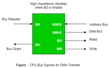
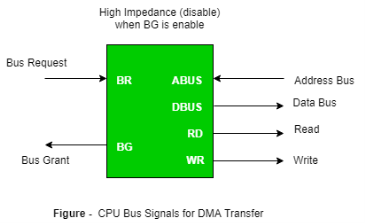
Figure 2 – CPU bus signals for DMA transfer
Bus Request : It is used by the DMA controller to request the CPU to relinquish the control of the buses.
Bus Grant : It is activated by the CPU to Inform the external DMA controller that the buses are in high impedance state and the requesting DMA can take control of the buses. Once the DMA has taken the control of the buses it transfers the data. This transfer can take place in many ways.
Types of DMA transfer using DMA controller:
Burst Transfer :
DMA returns the bus after complete data transfer. A register is used as a byte count,
being decremented for each byte transfer, and upon the byte count reaching zero, the DMAC will release the bus. When the DMAC operates in burst mode, the CPU is halted for the duration of the data transfer.
Steps involved are:
Bus grant request time.
Transfer the entire block of data at transfer rate of device because the device is usually slow than the
speed at which the data can be transferred to CPU.
Release the control of the bus back to CPU
So, total time taken to transfer the N bytes
= Bus grant request time + (N) * (memory transfer rate) + Bus release control time.
Where,
X µsec =data transfer time or preparation time (words/block) Y µsec =memory cycle time or cycle time or transfer time (words/block) % CPU idle (Blocked)=(Y/X+Y)*100 % CPU Busy=(X/X+Y)*100 |
Cyclic Stealing:
An alternative method in which DMA controller transfers one word at a time after which it must return the control of the buses to the CPU. The CPU delays its operation only for one memory cycle to allow the direct memory I/O transfer to “steal” one memory cycle.
Steps Involved are:
Buffer the byte into the buffer
Inform the CPU that the device has 1 byte to transfer (i.e. bus grant request)
Transfer the byte (at system bus speed)
Release the control of the bus back to CPU.
Before moving on transfer next byte of data, device performs step 1 again so that bus isn’t tied up and
the transfer won’t depend upon the transfer rate of device.
So, for 1 byte of transfer of data, time taken by using cycle stealing mode (T).
= time required for bus grant + 1 bus cycle to transfer data + time required to release the bus, it will be
N x T
In cycle stealing mode we always follow pipelining concept that when one byte is getting transferred then Device is parallel preparing the next byte. “The fraction of CPU time to the data transfer time” if asked then cycle stealing mode is used.
Where, X µsec =data transfer time or preparation time (words/block) Y µsec =memory cycle time or cycle time or transfer time (words/block) % CPU idle (Blocked) =(Y/X)*100 % CPU busy=(X/Y)*100 |
Interleaved mode: In this technique , the DMA controller takes over the system bus when the microprocessor is not using it.An alternate half cycle i.e. half cycle DMA + half cycle processor.
Device Driver and It’s Purpose
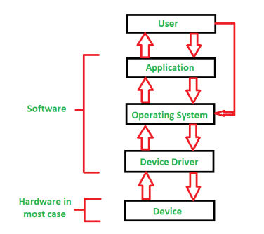
Device Driver in computing refers to a special kind of software program or a specific type of software application which controls a specific hardware device that enables different hardware devices for communication with the computer’s Operating System
A device driver communicates with the computer hardwares by computer subsystem or computer bus connected to the hardware.
Device Drivers are very essential for a computer system to work properly because without device driver the particular hardware fails to work accordingly means it fails in doing a particular function/action for which it has been created.
In a very common way most term it as only a Driver also when someone says Hardware Driver that also refers to this Device Driver.
|
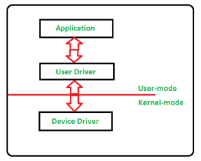
Figure 3 – Device Drivers
Working of Device Driver :
Device Drivers depend upon the Operating System’s instruction to access the device and performing any particular action. After the action they also shows their reactions by delivering output or status/message from hardware device to the Operating system.For Example a printer driver tells the printer in which format to print after getting instruction from OS, similarly A sound card driver is there due to which 1’s and 0’s data of MP3 file is converted to audio signals and you enjoy the music. Card reader, controller, modem, network card, sound card, printer, video card, USB devices, RAM, Speakers etc need Device Drivers to operate.
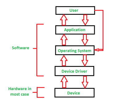
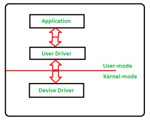
The following figure illustrates the interaction between user, OS, Device driver and the devices:
|
Figure 4 - Interaction between user, OS, Device driver
Types of Device Driver:
For almost every device associated with the computer system there exist Device Driver for the particular hardware.But it can be broadly classified into two types i.e.,
- Kernel-mode Device Driver –
This Kernel-mode device driver includes some generic hardwares which loads with operating System as part the OS these are BIOS, motherboard, processor and some other hardwares which are part of kernel software. These includes the minimum system requirement device drivers for each operating system. - User-mode Device Driver –
Other than the devices which are brought by kernel for working of the system the user also bring some devices for use during the using of a system that devices needs device drivers to functions those drivers falls under User mode device driver. For example user needs any plug and play action that comes under this.
Virtual Device Driver :
There are also virtual device drivers(VxD), which manages the virtual device. Sometimes we use same hardware virtually at that time virtual driver controls/manages the data flow from different application used by different users to the same hardware.
It is essential for a computer to have the required device drivers for all its parts to keep the system running efficiently.Many device drivers are provided by manufactures from beginning and also we can later include any required device driver for our system.
Buses in Computer Architecture
Every bus has three distinct channels of communication. The address bus, which is a unidirectional pathway that allows information to travel in only one direction, carries information about where data will be stored in memory.
The data bus is a bidirectional pathway that carries the actual data (information) to and from the main memory.
The control bus carries the control and timing signals needed to coordinate the activities of the entire computer. Think of this as a traffic cop.
Table 1: Three Components of a Bus
Bus Type | Description |
Address bus | A unidirectional pathway – information can only flow one way |
Data bus | A bi-directional pathway – information can flow in two directions |
Control bus | Carries the control and timing signals needed to coordinate the activities of the entire computer |
ISA Bus
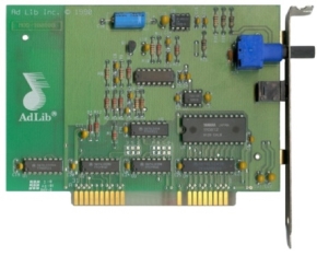
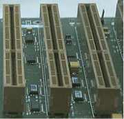
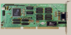
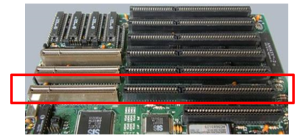
The Industry Standard Architecture (ISA) bus is one of the oldest buses still in use. Even though it’s been replaced with faster buses, ISA still has a lot of legacy devices that connect to it like cash registers, Computer Numerical Control (CNC) machines, and barcode scanners.
|
Figure 5: 8 and 16-bit ISA expansion slots
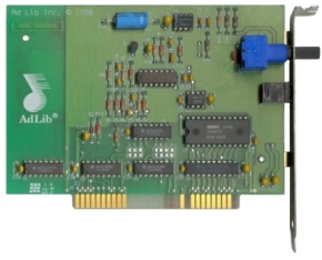
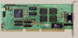
ISA remains largely unchanged since it was expanded to 16 bits in 1984. To avoid performance issues, it was augmented with additional high-speed buses. ISA persists because of the enormous base of existing peripherals.
|
Figure 6: 8-bit ISA board
EISA Bus
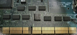
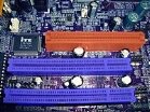
Extended Industry Standard Architecture or EISA is an upgrade to ISA. It doubled the data channels from 16 to 32 and allowed more than one CPU to share the bus. Even though it is deeper than the ISA slot, it is the same width which allows older devices to connect to it.
If you compare the pins (the gold part of the card that goes into the slot) on an ISA to an EISA card, you will see the EISA pins are longer and thinner. That is a quick way to determine if you have an ISA or an EISA card.
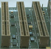
|
Figure 7: EISA expansion slots
Devices such as SCSI Host Bus Adapters (HBAs), network cards, or cash registers connect through EISA. EISA is much better suited for bandwidth-intensive tasks such as disk access and networking and has the following characteristics:
- Extends the ISA bus to 32 bits
- Allows more than one CPU to share the bus
- Bus mastering support was enhanced to provide access to 4 GB of memory
|
Figure 8: 16-bit EISA card
VESA Local (VL) Bus
The ISA bus quickly became a bottleneck as graphics processors; even the 32-bit EISA was not able to help that much.
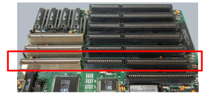
The Video Electronics Standards Association (VESA) Local bus was created to split the load and allow the ISA bus to handle interrupts and port I/O (input/output) and the VL bus to work with Direct Memory Access (DMA) and memory I/O. Because of its size and other considerations, this was only a temporary solution. The PCI bus quickly superseded the VL bus.
|
Figure 9: VL bus expansion slots
A VESA card has an additional set of pins and it is longer than ISA or EISA cards. Created in the early 90’s, it has a 32-bit bus and it was a temporary fix developed to help improve the performance of ISA.
|
Figure 10: VL bus board
PCI Bus
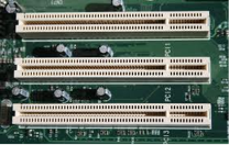
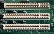
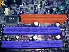
The PCI bus was developed to solve the issues previously discussed about ISA and VL-bus technology. PCI has a 32-bit data path and runs at half the system memory bus speed. One of its upgrades was it provided direct access to system memory for connected devices. This increased the performance of computers while eliminating the potential for interference from the CPU.
Today’s computers have mostly PCI slots.
|
Figure 11: PCI expansion slots
PCI is considered a hybrid between ISA and VL-Bus which provides direct access to system memory for connected devices. It uses a bridge to connect to the front side bus and CPU and is capable of higher performance while eliminating the potential for interference with the CPU.
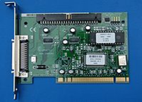
Also called the PCI Local Bus, this bus’s speed can be 32-bit or 64-bit. The 64-bit speed again improves the speed of moving data through the system.
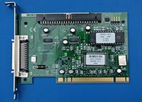
A motherboard can have up to five PCI slots allowing you to connect five external components to one controller. The PCI bridge chip regulates the speed of the PCI bus independently from the CPUs speed. This provides a higher degree of reliability because PCI hardware manufacturers know what specifications have to be met.
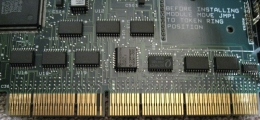
|
Figure 12: PCI board
AGP Bus
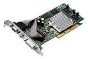
The Accelerated Graphics Bus (AGP) was created to handle the increased graphics requirements of computers. It has a 32-bit wide data path and runs at full bus speed. This doubled the bandwidth over PCI and eliminated having to share the bus with other components. This means that on a standard motherboard, AGP runs at 66 MHz instead of the PCI bus’s 33 MHz. This immediately doubles the bandwidth of the port in addition to not having to share that bandwidth with other PCI devices.
|
Figure 13: AGP expansion slots
AGP has a base speed of 66 MHz which doubles the speed of PCI. In addition, you can get slots that run into 2X, 4X, and 8X speeds. This makes an 8x expansion slot have a clock speed of 533 MHz. It also uses special signaling to allow twice as much data to be sent over the port at the same clock speed.
|
Figure 14: AGP Video Card
PCI Express (PCIe)
The latest slot added is PCI Express (PCIe). It was created to replace the AGP and PCI buses. It has a 64-bit data path and a base speed of 133 MHz, but its real performance enhancement was the addition of full duplex architecture. This allowed the card to run at full speed in both directions at the same time.
PCI Express slots run at 1X, 4X, 8X, and 16X giving PCI the fastest transfer speed of any slot type. The multiplier indicates the maximum transfer rate.
|
Figure 15: PCI Express Slots
PCI Express is backward compatible allowing a 1X card to fit inside a 16X slot.
|
Figure 16: 4x PCI Express Board
Summary
Each host is made up of two busses: a system bus and a shared bus. Each bus has three components: address bus, data bus, and control bus.Throughout the years, the size and speed of the expansion slots that connect external cards to one of the buses have varied. Cards and their expansion slots have improved from the original ISA to EISA and VESA, to the most current PCI.
Key takeaway
- The method that is used to transfer information between internal storage and external I/O devices is known as I/O interface. The CPU is interfaced using special communication links by the peripherals connected to any computer system. These communication links are used to resolve the differences between CPU and peripheral. There exists special hardware components between CPU and peripherals to supervise and synchronize all the input and output transfers that are called interface units
References
1 Computer system architecture by M. Morris Mano
2 Computer Architecture and parallel processing by Kai Hwang, Briggs, McGraw
3 Hill
4 Computer Architecture by Carter, Tata McGraw Hill.
5 Computer System Organization and Architecture by John D. Carpinelli, Pearson Education
