Unit - 4
Steering geometry
- Ackerman steering geometry is a geometric arrangement of linkages in the steering of a car or other vehicle designed to solve the problem of wheels on the inside and outside of a turn needing to trace out circles of different radii.
- The intention of Ackermann geometry is to avoid the need for tires to slip sideways when following the path around a curve.
- Intersecting the axes of the front wheels on this line as well requires that the inside front wheel be turned, when steering, through a greater angle than the outside wheel.
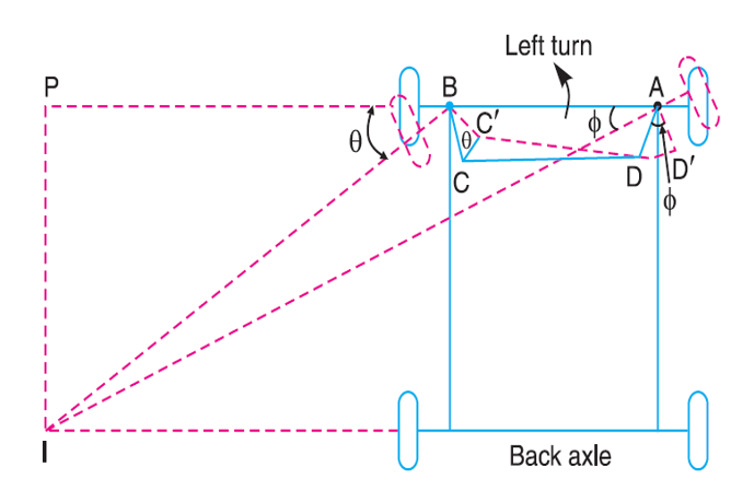
Fig 1. Ackerman steering geometry
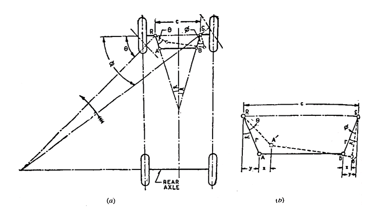
Fig 2. Ackermann steering mechanism.
(a) Outline of mechanism
(b) Details of enlarged scale
Let l = length of track rod, and
r = length of links RA and SB
Then referring Fig. 27 (b) and neglecting the obliquity of the track rod in the turned position, the movements of A and B in the horizontal direction may be taken to be same (each equal to 'x')
Then, sin (α + θ) = (y + x)/r
And, sin (α – φ) = (y – x)/r
On adding,
Sin (α + θ) + sin (α – φ) = 2y/r = 2sin α
The mechanism gives only 3 positions for correct steering; one when θ = 0 and the other two each corresponding to the turn to right or left (at a fixed turning angle). However, for other angles also it gives a close approximation to the ideal condition.
Further this has the advantage that it employs pivots and not sliding constrains, due to which reason its maintenance is easier. That is why it is universally employed. However, lately the automobile designers do not care to follow the Ackermann mechanism very strictly on account of the improvement in the suspension and tyres.
Any small deviation from the true rolling angles can be readily corrected by the tyres sidewall flexibility and tread distortion. Rather it is endeavoured to obtain the smallest value of the turning circle.
It may be noted that while parking, it is easier to steer a vehicle in reverse than in the forward direction because the rear wheels turn on smaller radius than the front wheels.
Example
The front axle of a car has pivot centres 1 1 m apart. The length of each steering arm is 150 mm, while the track rod is of 1.0 metre length. Calculate the wheelbase for perfect rolling of the car wheels when the inner wheel stub axle is at 55° to the rear centre line.
Solution.
Referring fig. 27(a),
θ = 90 – 25 = 35°
r = 150mm = 0.15m
l = 1.0m
c = 11m
Sin α = (c - l)/2r = (1.1 - 1.0)/ (2 x 0.15) = 0.333
α = 19.45°
From Equation (8.6),
Sin (19.45° + 35°) + sin (19.45° - φ) = 2 sin 19.45°
i.e. 0.814 + sin (19.45° - φ) = 0.667
φ = 27.9°
From equation of correct steering,
Cot φ – cot θ = c/b
Cot 27.9° - cot 35° = 1.1/ b
1.888 – 1.428 = 1.1/b
Wheel base, b = 2.39m
Key Takeaways:
- Outside of a turn needing to trace out circles of different radii.
- However, for other angles also it gives a close approximation to the ideal condition.
- Rather it is endeavored to obtain the smallest value of the turning circle.
- Worm and Wheel Steering Gear.
- Worm and Roller Steering Gear.
- Re-circulating Ball type Steering Gear.
- Rack and Pinion type Steering Gear
- Cam and Peg Steering Gear.
- Cam and Double lever Steering Gear.
- Worm and Sector Type Steering Gear.
1. Worm and Wheel Type:
This form of steerage equipment has a rectangular reduce screw threads on the quit of the steerage column; which paperwork a Trojan horse, on the quilt of it a Trojan horse wheel is outfitted and works rigidly with it.
Generally included shaft is used for the trojan horse wheel.
The trojan horse wheel may be became to a brand new role the drop arm may be readjusted to the best running role.
2. Re-circulating Ball Type:
In this form of equipment field the infinite chain of balls are furnished among the computer virus and nut members.
The nut shape a hoop of rack having an axial movement.
So that the arena at the rocker shaft racks, the balls roll constantly among the computer virus and nut.
Being furnished with go back chambers on the ends of the computer virus.
3. Rack and Pinion Type:
In this kind of steerage a pinion is supplied the lowest stop of the steerage column.
The enamel of the pinion wheel in mesh with corresponding enamel supplied at the rack, the stop of that are linked to the stub axle via the rod.
The rotating movement of the pinion operates the rack in FORE and AFT course which in flip operates the stub axle.
4. Cam and Lever Type:
The cam and lever guidance makes use of one or lever studs outfitted in taper curler bearing.
When the computer virus with inside the shape of helical groove rotates the stub axle and it additionally rotates together with it.
This imports a turning movement to the drop arm shaft.
5. Worm and Sector Type:
- In this kind the trojan horse at the give up of the guidance shaft meshes with a zone installed on a zone shaft.
- When the trojan horse is turned around through rotation of the guidance wheel, the arena additionally flip rotating the arena shaft.
- Its movement is transmitted to the wheel thru the linkage.
- The zone shaft is connected to the drop arm or pitmen arm.
6. Cam and Peg Steering Gear:
- This sort of steerage box, in vicinity of worm, a cylindrical shaft, supported with the aid of using curler bearing with inside the housing.
- The cylindrical shaft carried a deep spiral groove, commonly a variable pitch on its floor among its bearing and this shaft is called a cam.
- A necessary rocker arm and shaft is located half-manner alongside the cam. At the unfastened quit of the rocker arm a conical peg is equipped which engages the groove.
Key Takeaways:
- Generally included shaft is used for the trojan horse wheel.
- This imports a turning movement to the drop arm shaft.
- Its movement is transmitted to the wheel thru the linkage.
- An necessary rocker arm and shaft is located half-manner alongside the cam.
Working of Power Steering
The strength guidance unit is positioned on the decrease give up of the guidance column in location of the standard traditional guidance gear. It is hooked up with the aid of using oil strains to the hydraulic pump established at the generator. The pump with a comfort valve avoids immoderate oil pressures.
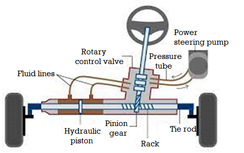
Fig 3. Power steering Unit
The power steering unit has:
- A valve frame with 4 valves.
- Two electricity cylinders have pistons one on every side.
The Valves will supply the oil to assist in creating a turn. This works at the endwise motion of the guidance column shaft. The guidance wheel rotates the bug. Thus it imposes cease-sensible thrust (both up and down) at the bug as according to the course of rotation. This creates the motion of the guidance column shaft via a small fraction of an inch.
This motion admits oil beneath Neath strain in a single or the opposite cease of the electricity cylinder. This makes the piston flow in a single or any other course. This movement is carried to the pitman shaft via the rack and pinion arrangement.
Electric Power Steering:
- An electricity steerage is a mechanical tool prepared on a motor automobile that facilitates drivers steer the automobile with the aid of using augmenting steerage attempt wished to show the steerage wheel, making it less complicated for the automobile to show or manoeuvre at decrease speeds.
- Hydraulic or electric powered actuators upload managed power to the steerage mechanism, so the driving force can offer much less attempt to show the instructed wheels while using at standard speeds, and decrease drastically the bodily attempt essential to show the wheels while a automobile is stopped or transferring slowly.
- Power steerage also can be engineered to offer a few synthetic remarks of forces appearing at the instructed wheels. Hydraulic electricity steerage structures for vehicles increase steerage attempt thru an actuator, a hydraulic cylinder this is a part of a servo gadget.
- These structures have an immediate mechanical connection among the steerage wheel and the linkage that steers the wheels. This method that electricity-steerage gadget failure (to reinforce attempt) nevertheless lets in the automobile to be instructed the use of guide attempt alone.
Hydraulic Power Steering:
- The winning kind of energy steerage from the Nineteen Fifties to the early 2000s became hydraulic help.
- Hydraulic energy steerage uses, as its call indicates, hydraulic fluid it's pressurized through a pump pushed off the engine.
- Although it served the car global properly for the ones 50 years, there are some downsides to this kind of system: there may be wasted energy, for the reason that pump is jogging continuously, even if the automobile is using instantly and there may be no help needed.
- Plus, the hydraulic fluid desires to get replaced periodically, and if any of the hydraulic strains springs a leak, it now no longer best makes a mess, however the energy help is lost.
Key Takeaways:
- The pump with a comfort valve avoids immoderate oil pressures.
- Thus it imposes cease-sensible thrust (both up and down) at the bug as according to the course of rotation.
- The winning kind of energy steerage from the Nineteen Fifties to the early 2000s became hydraulic help.
- These structures have an immediate mechanical connection among the steerage wheel and the linkage that steers the wheels.
A stay the front axle, in comparison to the useless axle, has the extra characteristic of transmitting the using energy taken from a switch gearbox to the front wheels having an exceptional swivelling mechanism. The stay the front axles even though similar to the equipment axles have a few distinction on the axle 1/2 of shafts stop in which the wheels are mounted. A useless the front axle has sufficient tension and electricity to hold the burden of the automobile from the springs to the front wheels.
Front wheels of the car are established on the front axles. Functions of the front axle are listed below:
(a) It helps the load of the front a part of the car.
(b) It allows steering.
(c) It absorbs torque carried out on it because of braking of car.
Construction and Operation
Front axle is made from I-phase within side the centre component and round or elliptical phase on the ends. The unique x-phase of the axle makes it capable of withstand bending hundreds because of weight of the car and torque carried out because of braking.
There are two types of front axles:
(a) Dead front axle, and
(b) Line front axle.
Dead Front Axle
These axles have enough rigidity and electricity to take the weight. The ends of the front axle are definitely designed to accommodate stub axles.
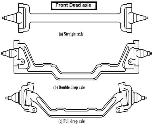
Fig 4: Dead Front Axle
Line Front Axle
- Line axles are used to transmit strength from tools container to the front wheels.
- Line the front axles despite the fact that, the front wheels.
- Line the front axles despite the fact that resemble rear axles but they may be specific on the ends wherein wheels are mounted.
- Maruti-800 has line the front axle.
Key Takeaways:
- A useless the front axle has sufficient tension and electricity to hold the burden of the automobile from the springs to the front wheels.
- Front axle is made from I-phase within side the centre component and round or elliptical phase on the ends.
- The ends of the front axle are definitely designed to accommodate stub axles.
The Double Wishbone suspension additionally has an unbiased design, so the turning perspective and suspension motion will now no longer have an effect on the geometry perspective, due to the fact the perspective will stay constant. The Double Wishbone suspension has drawbacks because of the pretty big area it requires. On pinnacle of that, whilst you need to update a surprise breaker or surprise absorber, the disassembly manner takes a protracted time.
To keep away from diverse harm to the car, you could do spooring regularly.
1. Rigid Axle Suspension
The important characteristic of this suspension is its wheels at the rear left and right. The wheels are linked into one axle that is usually called the axle. The inflexible axle suspension has 2 fashions at once, particularly the Axle Rigid version that is ready with leaf springs, and the Axle Rigid version that is ready with a coil spring or regularly called a spring.
- This suspension has pretty right exceptional and may be implemented in diverse forms of cars.
- It in all fairness easy due to the fact it could paintings with simply one stable piece and is geared up with 2 springs.
- Suspension can assist hose down the vibrations or shocks that arise while you are on a avenue this is choppy or has a tendency to be bumpy.
With a very good exceptional suspension vehicle, you could live seated with none disruption. The suspension isn't always handiest beneficial to assist lessen vibrations while the auto is riding however could make managing more secure and permit the auto can run stably at the avenue. With its very sizable use, of course, the suspension is a have to-have aspect in a vehicle and it have to get more care.
2. Macpherson Suspension
Macpherson is a suspension whose call is taken from its inventor, Earle Macpherson. Lots of automobiles round the sector use Macpherson suspension. Many automobile producers like this suspension, as it has an lower priced rate and additionally has pretty easy components.
- This suspension is likewise very clean to reap as it’s allotted widely.
- The drawback of Macpherson’s suspension is that it's far much less capable of get hold of hundreds and the lean perspective constantly modifications while the auto is became or turns, this makes the tires much less capable of grip the street asphalt properly.
3. Double Wishbone Suspension
Double Wishbone is a kind of suspension that has 2 palms that help the suspension system, specifically the higher and decrease palms. With this suspension, the automobile can run stably.
4. Independent Suspension
Independent suspension is a specifically designed suspension due to the fact the proper and left wheels on the rear aren't linked immediately however alternatively via way of means of axle joints If the rear wheel steps on a hole, of course, the automobile will now no longer rock and that is due to the fact most effective the left suspension moves.
- Independent suspension is certainly extensively utilized in luxurious cars.
- The unbiased suspension has a extra complicated creation and the axle moves are at the same time unbiased.
This suspension is likewise ready with bendy joints. This sort of suspension remains pretty expensive, so its use is ordinarily in costly cars. You also can experience the consolation of the Independent Suspension whilst riding the Wuling Cortez CT Type S. This own circle of relative’s vehicle from Wuling gives consolation via Independent Suspension at the rear wheels.
5. Rigid suspension – Leaf Spring
Rigid – Leaf spring is one form of suspension this is extensively carried out in vehicles circulating in Indonesia and is typically utilized in business kind vehicles or vintage kind vehicles.
- This suspension is normally used on the rear of the auto due to the fact this suspension is stiff.
- This suspension has a reasonably easy and easy construction.
- Cars that use this suspension normally have a reasonably excessive degree of resistance.
6. Trailing Arm Suspension
Trailing Arm is a sort of suspension whose commands are nearly similar to three Links – Rigid, despite the fact that the running machine could be very distinct. The manner it really works is likewise distinct from the three Links – Rigid or different styles of suspension. The Trailing Arm suspension has linked from the proper facet to the left. This sort of suspension is typically located behind the car.
7. Air Suspension
Air Suspension is one of the advanced suspensions that has extremely good performance, so this sort of suspension is broadly utilized in luxurious cars. Even in luxurious cars, the automobile’s suspension may be adjusted the usage of a laptop and this permits the adjustment to be executed properly. The downside of this suspension is that it has a completely complex production whilst as compared to different styles of suspension. Not handiest that, however this suspension additionally has a completely luxurious price. Those are the 8 styles of automobile suspensions that exist today. Hopefully, this statistics can upload in your car knowledge.
Key Takeaways:
- This suspension has pretty right exceptional and may be implemented in diverse forms of cars.
- Macpherson is a suspension whose call is taken from its inventor, Earle Macpherson.
- Independent suspension is certainly extensively utilized in luxurious cars.
- The Trailing Arm suspension has linked from the proper facet to the left.
- The downside of this suspension is that it has a completely complex production whilst as compared to different styles of suspension.
Leaf Spring:
A leaf spring is a kind of spring made via way of means of some of plates (leaves) stacked upon every different in growing order of sizes. It is used to soak up shocks and vibrations in heavy business automobiles like trucks, vans, buses, etc.
Construction of Leaf spring
Following are the parts of leaf spring
- Metal plates or leaves
- Central clamp
- Rebound clips
![Semi-elliptic leaf spring [2]. | Download Scientific Diagram](https://glossaread-contain.s3.ap-south-1.amazonaws.com/epub/1642644908_2779517.png)
Fig 5. Construction details of leaf spring
Metal Plates or Leaves:
The leaf spring includes some of metallic plates additionally referred to as leaves layered upon every different with inside the lowering order in their size. The leaves are given a curvature known as the camber which offers the leaf spring its semi-elliptic look.
These rolled ends of the grasp leaf are called the eye. Just beneath the grasp leaf, some other nearly full-duration leaf referred to as the second one grasp leaf and is located to help the grasp leaf. (refer figure) The ultimate leaves are called “graduated leaves”.
Central clamp
The important clamp’s characteristic is to maintain all of the leaves together. It includes U bolts and an important bolt in order that the leaves don’t fall apart.
Rebound clips
The rebound clips are made of metal bands positioned at a positive function on both aspect of the valuable clamp and its important feature is to save you the leaf spring from failing at some stage in a rebound. A leaf spring generally does now no longer destroy whilst it's far compressed i.e. whilst the axle of the car undergoes a bump.
However, whilst the pressure is unexpectedly eliminated the leaf spring may fail.
This is due to the fact whilst the spring is being compressed from under, every leaf is supported with the aid of using the leaf under it, but, whilst the weight is unexpectedly launched it might now no longer locate help if now no longer for the rebound clips which preserve them collectively and offer help.
Working of leaf spring
- When the automobile is going over a bump, the axle has a tendency to transport up and down.
- However, because the leaf spring is provided, it helps the axle and allows take in the vibrations and shocks.
- Assume that a truck is going over a velocity bump, this reasons the wheel and the axle to be pressured upwards.
- So because the axle movements upwards, the leaf spring movements alongside it however because of its semi-elliptical form and it absorbs in addition to transfers the upward pressure to the chassis frame.
- The shackle of the leaf spring allows it to enlarge whilst pressure is applied.
Advantages of leaf spring
The following are the advantages of leaf spring:
- Leaf springs are mild in weight and strong.
- It offers correct damping action.
- It offers correct aid to the axle and the chassis.
- Leaf springs are easy in design.
- Leaf springs can face up to a big quantity of load whilst as compared to helical springs.
Key Takeaways:
- A leaf spring is a kind of spring made via way of means of some of plates (leaves) stacked upon every different in growing order of sizes.
- The leaves are given a curvature known as the camber which offers the leaf spring its semi-elliptic look.
- When the automobile is going over a bump, the axle has a tendency to transport up and down.
In easy terms, Brakes are the element in any automobile which assist in lowering the velocity or preventing the automobile.
To observe the brakes, we must both press a pedal or pull a lever. But just assume how this transmission of pressure occurs from pedal/lever to brakes placed at wheels?
To obtain this we've got exclusive systems (Pneumatic/Air Brake) to select from relying at the requirement:
Mechanical –
Wherein metallic cables can be accountable to use the brakes at wheels, the instant you pull the brake lever.
Ex – Parking brakes of a vehicle or Rear drum brake of a motorcycle is normally operated via. Cables.
Hydraulic –
Hydraulic oil is accountable to by skip at the motive force carried out pressure via. Pedal or lever to the brake piston which in flip applies the brake on wheels.
Ex – Normal Braking gadget of a vehicle or a Disc Brake on a motorcycle.
Pneumatic –
As the phrase speaks for itself, it operates via. Air. Braking gadget preserve a excessive stress air interior it and second motive force applies brake, stress with inside the line begins off evolved dropping. This effects in making use of brakes on wheels. It will sound a piece peculiar however that is the way it works.
Ex – Heavy automobiles like Truck, Bus, Trailer or Train. Ever observed a bus motive force on attaining destination, he pulls up a button on dashboard & weird ‘phisshhh’ sound we should hear. With that button he releases the air stress to have interaction the brakes, acts as a Parking Brake for heavy automobiles.
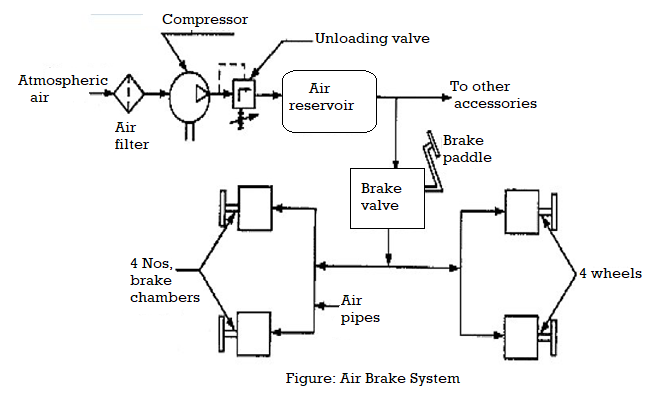
Working of Pneumatic Brake:
- Pneumatic or Air brakes perform on compressed air.
- Entire braking machine pipeline is first of all charged up with compressed air to hold gold standard stress.
- Moment motive force applies pressure on brake pedal, air stress drop initiates via. Motive force’s brake valve.
- Compressed air from auxiliary cylinder rushes in to the brake cylinder inflicting brake to get engaged.
- This is how pneumatic brakes paintings in actual time operation of brake pedal through motive force.
- This is how Parking Brake works in pneumatic braking machine of heavy vehicle.
Advantages of Air Brakes:
- Air brakes are used as an opportunity to hydraulic brakes which can be used on lighter motors together with automobiles.
- Hydraulic brakes use a liquid (hydraulic fluid) to switch stress from the brake pedal to the brake shoe to prevent the automobile.
- Air brakes have numerous benefits for huge multitrailer motors: · The delivery of air is unlimited, so the brake device can by no means run out of its working fluid, as hydraulic brakes can. Minor leaks do now no longer bring about brake failures.
- Airline couplings are less difficult to connect and detach than hydraulic lines; there's no risk of letting air into hydraulic fluid. So air brake circuits of trailers may be connected and eliminated without difficulty through operators with little training.
- Stair now no longer handiest serves as a fluid for transmission of pressure, however additionally shops ability power. So it may serve to govern the pressure applied.
- Air brake structures consist of an air tank that shops enough power to prevent the automobile if the compressor fails.
- Air brakes are powerful in spite of sizeable leakage, so an air brake device may be designed with enough "fail-safe" ability to prevent the automobile thoroughly even if leaking.
Key Takeaways:
- To observe the brakes, we must both press a pedal or pull a lever.
- With that button he releases the air stress to have interaction the brakes, acts as a Parking Brake for heavy automobiles.
- Minor leaks do now no longer bring about brake failures.
- Stair now no longer handiest serves as a fluid for transmission of pressure, however additionally shops ability power.
Hydraulic brakes use the incompressible fluid houses to actuate a braking mechanism and offer the braking components (discs, drums, pads, etc.) with pressure to interact and do away with strength from a transferring machine. Brakes fluctuate from one to the subsequent with inside the manner they interact, operate, and perform. The hydraulic fluid via hydraulic traces and forces the brake cylinders to move, actuating the braking device. Braking structures can variety in length from an easy hand lever operated brake on a snowmobile to complex, energy assisted structures.
Specifications
Performance specs to don't forget whilst choosing a hydraulic brake include, however aren't confined to:
- Torque Rating— the most torque score for the brake ought to same or exceed the application's requirement.
- Power— the most electricity score for the brake.
- Speed— the most rotary velocity score. This specification applies handiest to rotary brakes.
- Maximum Pressure— the most stress for a hydraulic brake. Shaft
- Configuration—Brake can be established in-line, parallel, or proper angle.
Types
Energy may be eliminated via way of means of a brake in numerous ways. Here are a few distinct methods to braking:
Band
Band brakes are the handiest sort of brake. They have a metallic band covered with warmth- and wear-resistant friction material.
Drum
Drum brakes press footwear towards a spinning surface. They are regularly used on car rear wheels.
Disc
Disc brakes have brake pads, a calliper, and a rotor. During operation, the brake pads are squeezed towards the rotor. Disc brakes have exact warmth dissipation properties.
Cone
Cone brakes encompass a cup and a cone this is covered with a warmth- and wear-resistant friction material. During actuation, the cone is pressed towards the mating cup surface. Cone brakes aren't normally used.
Several engagement techniques are to be had for hydraulic brakes, including:
- Noncontact—braking motion is accomplished thru a non-touch era consisting of a magnetic field, eddy currents, etc. Friction—Friction among touch surfaces transmits energy. This is the maximum not unusual place sort of brake.
- Toothed—toothed touch surfaces transmit energy without slipping or warmth generation. Teeth are engaged simplest whilst stopped or strolling at a sluggish speed (< 20 rpm).
- Wrap Spring—a coiled spring wraps downward onto the rotating element. The brake is disengaged whilst the spring is uncoiled through a manipulate tang at its end.
- Oil Shear—braking motion is engaged through the viscous motion of the shearing of transmission fluid.
Applications
- Though Hydraulic Brakes are maximum acquainted to us as they're utilized in our cars, they're found in many different transportation and rolling inventory industries together with aerospace, heavy transport, marine, and off-highway.
- Hydraulic brakes also are discovered in commercial device like conveyors, system tools, motors, pumps, robotics, and automation.
- Hydraulic brakes are considerably less difficult to modulate than mechanical brakes; you get extra pressure added to the pads, and, as a result, extra preventing energy for the equal input. Additionally, you'll enjoy quicker and extra steady pad withdrawal upon release.
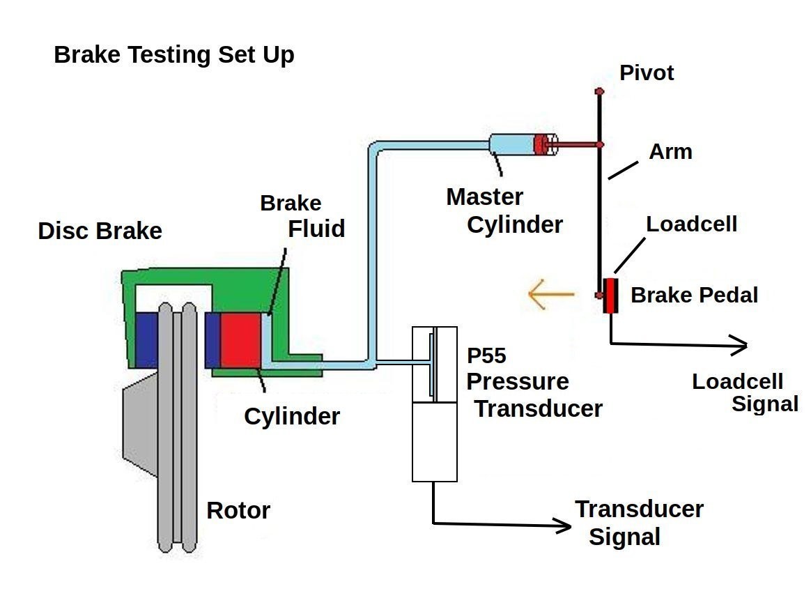
Fig 6. Hydraulic Braking System
Key Takeaways:
- Braking structures can variety in length from a easy hand lever operated brake on a snowmobile to complex, energy assisted structures.
- The brake is disengaged whilst the spring is uncoiled through a manipulate tang at its end.
- Hydraulic brakes also are discovered in commercial device like conveyors, system tools, motors, pumps, robotics, and automation.
- Additionally, you'll enjoy quicker and extra steady pad withdrawal upon release.
ABS or often referred as anti-skid braking systems is a safety system used on different airplanes and other moving vehicles like cars, trucks, buses etc. ABS first came into existence in 1920s developed by a French researcher to assist braking on aircraft. In 1970's the modified and reformed version of ABS was presented to the commercial market. Today it is used in every car and motorcycle for steering and traction control.
ABS prevents the automobile tyres/wheels from locking up and helps in maintain the steering control during braking by keeping tractive contact with the road surface. This automated system works on two techniques which was successfully used by skilled drivers before ABS widely used. ABS follow the principle of
- Threshold braking
- Cadence braking.
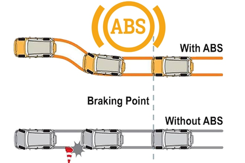
Fig 7. ABS Technology
When instant brakes are applied, there is a chance of an immediate loss of traction between the road and wheels leading to skidding of the tyres. The situation worsens if all this occurs irrepressibly. In this situation the automobile remains in motion, and the loss of traction may result in driver loosing steering control leading to a mishap. So here an ABS system provides rescue. As ABS functions, the brakes are pressed and relieved several times in a second. Due to this the tyres does not lock up during braking. The automobile slows in speed down retaining its grip, and the existing traction permits the driver to maintain navigation control. As such, the driver steers the automobile avoiding an accident.
ABS usually provides improved automobile control and minimizes stopping distances on desiccated, slippery, or snow-covered surfaces. ABS can also considerably maximize braking distance, while still providing steering control.
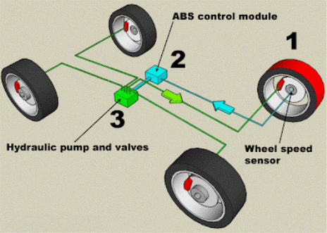
Fig 8. ABS Components
The four major components of a typical anti-lock braking system (Fig 14) are:
- Sensors - monitors how fast the wheels are spinning
- Valves - permits, blocks and relieve pressure on the brakes
- Pump - filled with fluid for applying pressure to the brake drums when needed.
- Controller - Consist of an ECU (electronic control unit) which is the heart. It takes data from sensors and decide if pumping of the brake is required or not.
ABS works by releasing and then 'pumping' the brakes to automobile wheels in hard braking conditions. As the sensors notice that the speed of any wheel (s) is dipping significantly in comparison to other wheels, the ECU instantly sends the indication to the valves of the desired wheel(s) to reduce the pumping (brake) pressure, and the valves get shut off. After sometime, the wheels start to quicken again, sensor sends the signal to ECU, which in turn sends an indication to increase the brake pressure and open the valve and ultimately brakes are applied. This cycle keeps on repeating till brake application becomes normal. So fundamentally, this system works in three stages:
- Brake pedal is pressed/released
- Speed sensors detect skidding/ locking or decrease in speed
- Pumping the brakes
Key Takeaways:
- ABS first came into existence in 1920s developed by a French researcher to assist braking on aircraft.
- As ABS functions, the brakes are pressed and relieved several times in a second.
- Controller - Consist of an ECU (electronic control unit) which is the heart.
- ABS works by releasing and then 'pumping' the brakes to automobile wheels in hard braking conditions.
It is also known as EBL (electronic brake force limitation). It is an automated automobile braking technique (technology) used for automatically distributing the force applied on each automobile's wheels. The force distribution to each wheel depends on the road conditions, speed of the automobile, loading of the vehicle, etc.
EBL is a modification of the ABS and it make sure that the appropriate quantity of force is distributed to each tyres for bringing the vehicle to a completely stop. As ABS manages that the vehicle do not get locked up on heavy braking, EBD ensures that each wheel gets the suitable amount of braking force. Through EBD we can exert more or less braking force to each tyres for maximizing the stopping power though maintaining steering control.
Along with ABS, the EBL technology these days can be found in mainstream cars like MG HS, and helps to expand driving experiences.
The EBD consists of 3 major components:
- Sensors: It determines the wheel along with the rate at which the vehicle is moving. These sensor senses that steering losing control and sends signals to ECU.
- ECU: It’s used to measure the slip ratio (the difference b/w rate of tyre movement and vehicle speed) and send command to modulator for maintain the slip ration in reasonable range.
- Force Modulators: These modulators control the braking force applied on each wheel.
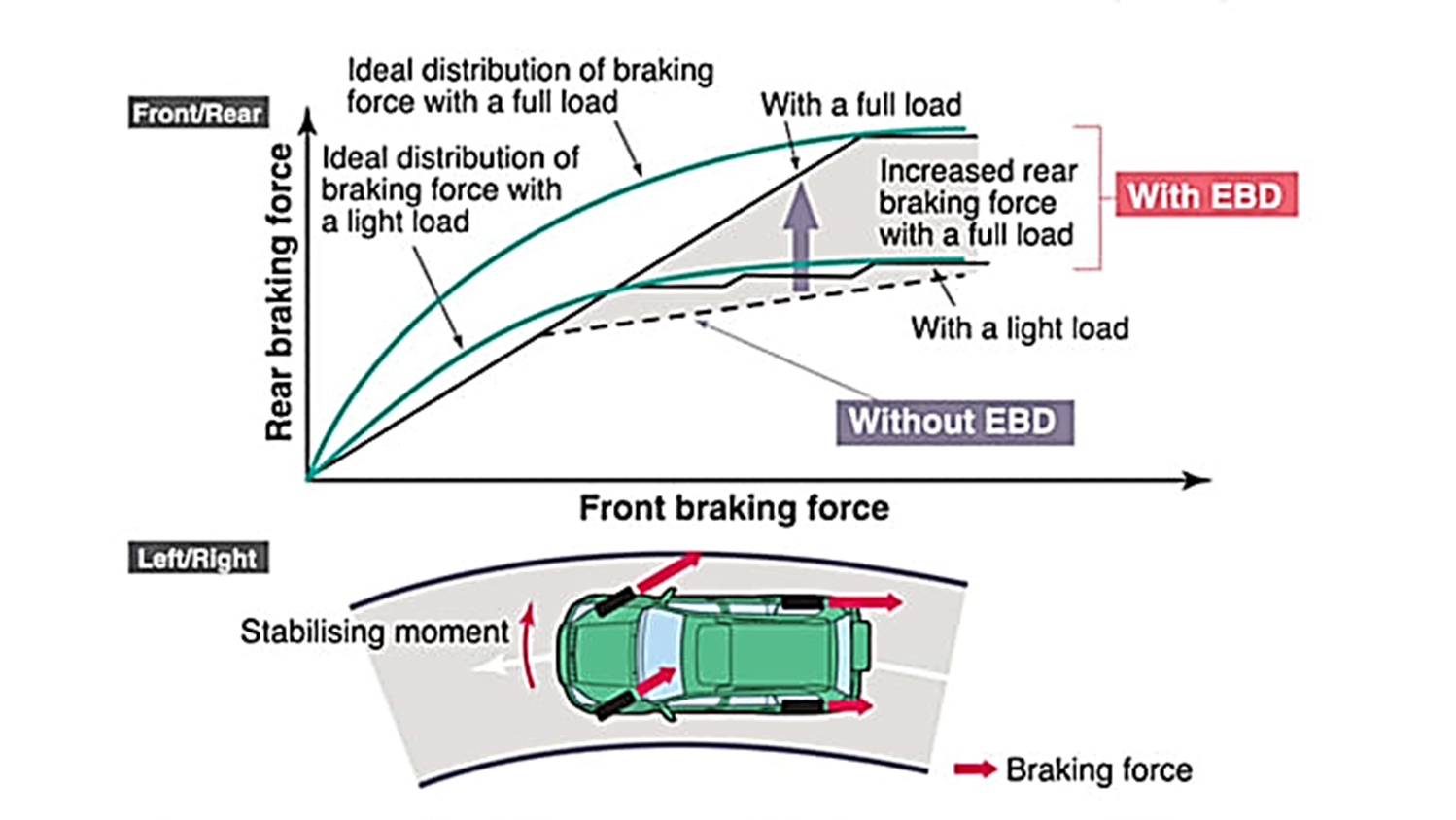
Fig 9. Working of EBD
When brakes are applied and the vehicle slows down, its weight shifts to front end. This
Increased weight at front maximizes the grasp of the front tires but it reduces the grip at rear end making the rear tires to slip. As such car can tail in one direction or even spin. With ABS the different wheel valves do not provides an adequate solution. To solve this problem modern vehicles are provided with EBL/EBD. With EBD, ECU regulates the slip ratio of each of the wheels independently. As the rear wheels are in danger of slipping, ECU applies less force to rear end while sustaining the force exerted to the front wheels.
EBD is also beneficial when the vehicle is braking while making a turn. During turning, rotation of the outer tyres is swifter as compared to inner tyres. If heavy braking is applied to inside tyres they can get lock causing oversteering and slipping of the vehicle. EBD senses the slippage of the inside tyres and reduces the brake pressure on these tyres without compensating the force on the outside tyres.
Key Takeaways:
- It is an automated automobile braking technique (technology) used for automatically distributing the force applied on each automobile's wheels.
- Force Modulators: These modulators control the braking force applied on each wheel.
- EBD is also beneficial when the vehicle is braking while making a turn.
- EBD senses the slippage of the inside tyres and reduces the brake pressure on these tyres without compensating the force on the outside tyres.
TCS objective is to regulate and uphold the vehicle stability during acceleration manoeuvres, i.e., avoiding spinning of the wheels when speed up on steep grade or a low frictional surface. TCS is a dynamic automobile safety technique. It prevents loss of traction of the wheels driven on roads. TCS is a regular safety feature in modern vehicle these days.
TCS becomes operational when the wheel torque and throttle input mismatches with the driving surface. TCS becomes handy in extreme weathers involving rainfall, snow and on slippery surfaces offering minimal to no grip. It allows the vehicle them to build up speed without losing grip.
The above-mentioned advantages are attained by the optimization of separate wheel torques by controlling the combination of different fuels, ignition system and brake torque of driven wheel.
TCSs are capable of utilizing the different parts used in ABS and amalgamation of these two technologies is becoming common today.
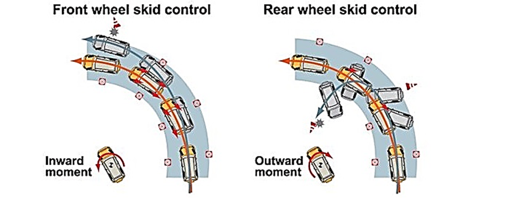
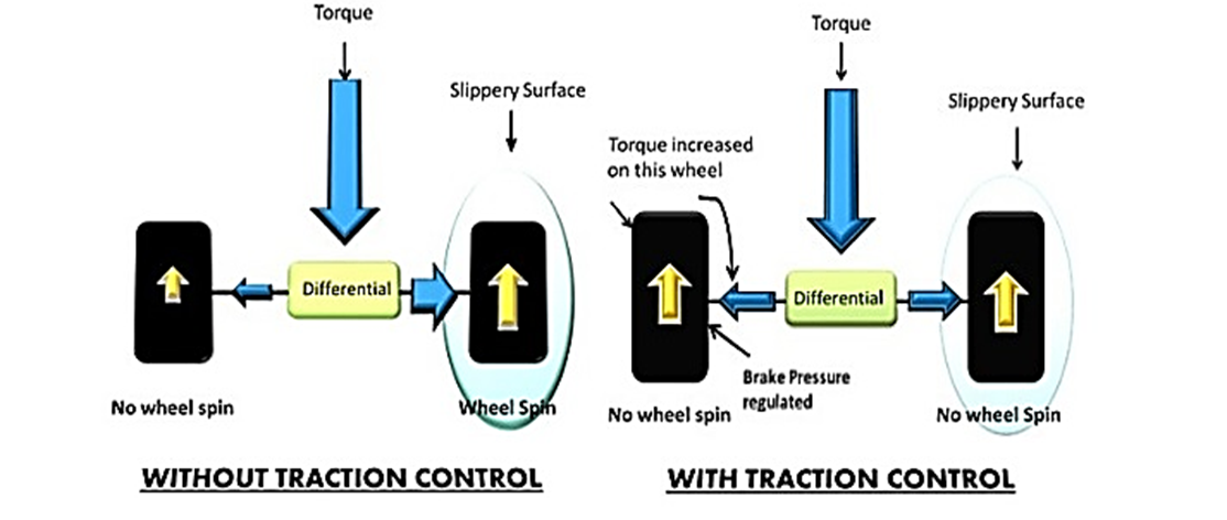
Fig 10. Traction Control
Key Takeaways:
- TCS is a dynamic automobile safety technique.
- TCS becomes operational when the wheel torque and throttle input mismatches with the driving surface.
- TCSs are capable of utilizing the different parts used in ABS and amalgamation of these two technologies is becoming common today.
References:
- Automotive Engineering- Hietner.
- Automobile Engineering - Narang.
- Automobile Engineering – Dr. Kirpal Singh
- Automotive Mechanics- Crouse.