Unit - 4
Non-conventional welding process
Laser Beam Welding is a combination welding process in which two metal pieces are consolidated by the utilization of laser. The laser bars are engaged to the depression between the two metal pieces to be joined. The laser pillars have enough energy and when it strikes the metal pieces produce heat that softens the material from the two metal pieces and fills the hole. In the wake of cooling a solid weld is shaped between the two pieces.
It is a productive welding process and can be computerized with apply autonomy hardware no problem at all. This welding strategy is for the most part utilized in the car business.
Working Principle
It takes a shot at the rule that when electrons of a molecule gets energized by retaining some energy. And afterward after some time when it returns back to its ground state, it transmits a photon of light. The convergence of this transmitted photon expanded by animated outflow of radiation and we get a high energy concentrated laser pillar.
Light enhancement by animated emanation of radiation is called laser.
Principle Parts
The principle parts or hardware of laser shaft welding are:
- Laser Machine: It is a machine that is utilized to create a laser for welding. The fundamental parts of the laser machine are demonstrated as follows.
- Power Source: A high voltage power source is applied over the laser machine to create a laser pillar.
- CAM: It is a PC helped producing in which the laser machine is incorporated with the PCs to play out the welding procedure. All the controlling activity during the welding procedure by laser is finished by CAM. It accelerates the welding procedure to a more prominent degree.
- CAD: It is called as Computer-supported Design. It is utilized to plan the activity for welding. Here PCs are utilized to plan the workpiece and how the welding is performed on it.
- Shielding Gas: A protecting gas might be utilized during the welding procedure so as to forestall the w/p from oxidation.
Working:
First, the arrangement of welding machine at the ideal area (in the middle of the two metal pieces to be joined) is finished.
After arrangement, a high voltage power supply is applied to the laser machine. This beginning the glimmer lights of the machine and it radiates light photons. The energy of the light photon is consumed by the particles of ruby precious stone and electrons get eager to their higher energy level. At the point when they return back to their ground state (lower Energy state) they produce a photon of light. This light photon again invigorates the energized electrons of the iota and produces two photons. This procedure keeps proceed and we get a concentrated laser bar.
This high thought laser shaft is engaged to the ideal area for the welding of the different sorts out. Focal point is utilized to centre the laser to the zone where welding is required. CAM is utilized to control the movement of the laser and workpiece table during the welding procedure.
As the laser pillar strikes the hole between the two metal pieces to be gone along with, it softens the base metal from both the pieces and breakers them together. After hardening, we get a solid weld.
This is the manner by which a laser Beam Welding Works.
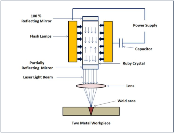
Figure 1: Laser Welding
Advantages:
- It creates high weld quality.
- LBW can be effectively computerized with mechanical apparatus for enormous volume creation.
- No cathode is required.
- No instrument wears since it is a non-contact process.
- The time taken for welding thick area is decreased.
- It is equipped for welding in those zones which are not effectively open.
- It can weld metals with divergent physical properties.
- It can be weld through air and no vacuum is required.
- X-Ray protecting isn't required as it doesn't deliver any X-Rays.
- It can be centred around little regions for welding. This is a result of its smaller light emission energy.
- A wide assortment of materials can be welded by utilizing laser bar welding.
- It produces a weld of angle proportion (for example profundity to width proportion) of 10:1.
Disadvantages:
- The starting expense is high. The hardware utilized in LBW has a significant expense.
- High upkeep cost.
- Due to the quick pace of cooling, breaks might be created in certain metals.
- High gifted work is required to work LBW.
- The welding thickness is restricted to 19 mm.
- The energy change productivity in LBW is low. It is for the most part underneath 10 %.
Application
The laser shaft welding is prevailing in the car business. It is utilized in the zone where enormous volume creation is required.
Electron Beam Welding:
Electron Beam Welding is a welding procedure using a heat created by a beam of high energy electrons. The electrons strike the work piece and their active energy changes over into thermal energy heating the metal with the goal that the edges of work sort are intertwined and joined out shaping a weld after Solidification.
The procedure is done in a vacuum chamber at a weight of about 2*10-7 to 2*10-6 psi (0.00013 to 0.0013 Pa). Such high vacuum is required so as to forestall loss of the electron’s energy in crashes with air atoms.
The electrons are produced by a cathode (electron firearm). Because of a high voltage (around 150 kV) applied between the cathode and the anode the electrons are quickened up to 30% - 60% of the speed of light. Dynamic energy of the electrons gets adequate for dissolving the focused-on weld. A portion of the electron’s energy changes into X-beam illumination.
Electrons quickened by electric field are then engaged into a slim bar in the centering curl. Avoidance loop moves the electron pillar along the weld.
Electron Beam is competent to weld work pieces with thickness from 0.0004" (0.01 mm) up to 6" (150 mm) of steel and up to 20" (500 mm) of aluminium. Electron Beam Welding might be utilized for joining any metals including metals, which are not really weldable by other welding strategies: recalcitrant metals (tungsten, molybdenum, niobium) and synthetically dynamic metals (titanium, zirconium, beryllium). Electron Beam Welding is additionally ready to join divergent metals.
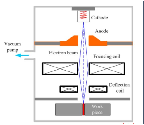
Figure 2: Electron Beam Welding
Advantages:
- Tight nonstop weld;
- Low mutilation;
- Thin weld and restricted heat influenced zone;
- Filler metal isn't required.
Disadvantages
- Costly hardware;
- High creation costs;
- X-beam light.
Ultrasonic Welding (USW) is a welding method that utilizes ultrasonic vibration of high frequency to weld the two sorts out. It is most usually used to weld thermoplastic materials and disparate materials. Metal with a slight area can likewise be welded with USW.
Working Principle:
A high frequency (20 kHz to 40 kHz) ultrasonic vibration is utilized to combine two plastic pieces. The high-frequency vibration creates heat vitality at the interface of the two pieces and melts the material. The softened material melded with one another to frame a solid weld on cooling and cementing.
Principle Parts
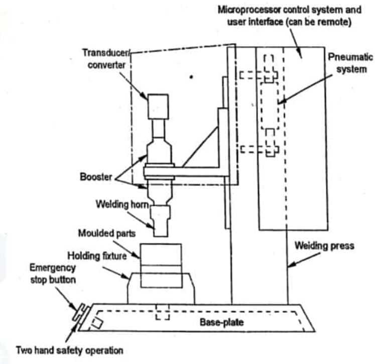
Figure 3: Ultrasonic Welding
The different principle parts or segments of ultrasonic welding are:
- A Press: It is utilized to apply pressure on the two plastic pieces to be joined. It might be of pneumatic or electric driven sort.
- Nest or anvil or fixture: It is a cinching gadget that is utilized to hold and brace the two plastic sorts out. It permits the high-frequency vibration coordinated to the interface of the two pieces.
- An Ultrasonic Stack: It comprises of the three parts, a converter or piezoelectric transducer, a promoter and a horn or sonotrode. These three components are tuned to take a shot at reverberate frequency of 15 kHz, 20 kHz, 30 kHz, 35 kHz or 40 kHz.
- Converter: It changes over the electrical signs into high-frequency mechanical vibration. What's more, it does as such through the piezoelectric impact.
- Booster: It changes the adequacy of vibration precisely. In some standard frameworks, it is utilized to clip the stack in the press.
- Horn or Sonotrode: It vibrates at high frequency and transmits the mechanical vibration to the two pieces to be welded. It likewise alters the abundancy precisely. It takes the state of the part. The horn is made of titanium or aluminium.
- An Ultrasonic Generator: It produces and conveys high-frequency electrical signs coordinating the reverberation frequency of the stack.
- Controller: It is utilized to control the development of the press and conveyance of the ultrasonic vitality.
Working Process of Ultrasonic Welding:
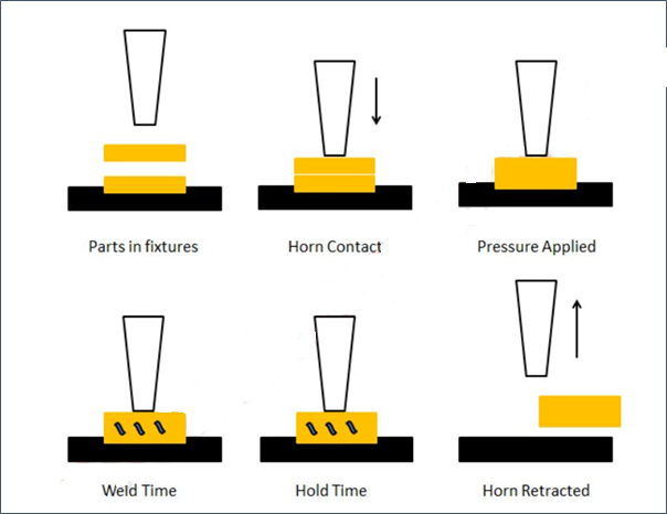
- The two plastic pieces to be joined are gathered in the nest (iron block or installation).
- The horn is reached at upper piece of the piece.
- A pressure is applied to the two pieces against the apparatus. The pressure is applied through the pneumatic or electric driven press.
- Horn is vibrated vertically at extremely high frequency (20 kHz to 40 kHz), transmits the mechanical vibration to the two plastic pieces. This produces heat vitality at the contact tip of the two surfaces and melts them.
- A clasping power is applied to the two pieces for a foreordained measure of time to intertwine them to shape a solid weld on cooling and hardening.
- After hardening, the clipping power is expelled and horn withdrew. The welded plastic part is removed from the apparatus as one piece.
Application
- It is for the most part utilized in PC and electrical, aviation and car, clinical, and bundling businesses.
- PC and Electrical Industries: Here it is utilized to join wired associations and to make associations in little fragile circuits.
- In car enterprises, it is utilized to gather huge plastic and electrical parts, for example, entryway boards, instrument boards, air conduits, lights, guiding wheels, and upholstery and motor segments.
- In aviation, it is utilized to join dainty sheet check and lightpressure materials like aluminium.
- It doesn't bring any contaminants or corruption into the weld. That is the reason it is utilized in clinical businesses.
- Things, for example, sedation channels, blood vessel channels, blood channels, dialysis tubes, pipettes, blood/gas channels, cardiometry supplies, and so on can be made utilizing ultrasonic welding technique.
- It is utilized to bundle various materials in nourishment businesses.
- It is utilized for bundling hazardous materials like explosives, firecrackers, and synthetic concoctions.
Advantages:
- Points of interest
- It is a quick welding process.
- It has Quick drying time for example the pieces don't stay for quite a while in the apparatuses to dry
- It tends to be handily mechanized.
- It creates a spotless and exact joint.
- It displays clean weld locales and doesn't require and finish up work.
- It creates a low warm effect on the materials.
Disadvantages:
- It can't be utilized to create enormous joints (more noteworthy than 250 x 300 mm).
- It requires uniquely planned joints, so it can reach during the welding procedure.
- High tooling cost for the apparatuses.
- The ultrasonic welding process is limited to the lap joints.
The Plasma Arc Welding:
The Plasma Arc Welding (PAW) and cutting procedure was designed by Robert M.Gage in 1953 and licensed in 1957. This procedure was exceptional in light of the fact that it could do exactness cutting on both thick and slender metal. It is likewise fit for spray coating hardening metal on different metals.
Principle
PAW is process where a mixture is created by the warmth which is created from a unique arrangement between a tungsten compound terminal and the water cooled spout (Non moved ARC) or between a tungsten composite cathode and the activity (moved ARC) .
This procedure utilizes two unique gases for two distinct purposes:
One gas is utilized to shape the Arc plasma.
Second gas is utilized to shield the bend plasma.
Equipment:
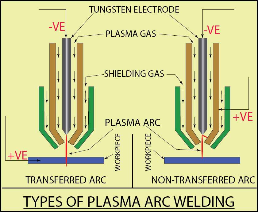
Figure 4: Plasma Arc Welding
Force supply: A DC power source with a hanging qualities and open circuit's voltage of 70 volts or above is especially appropriate for plasma circular segment welding.
Ordinary welding parameters:
Current: 50-350A
Voltage: 27-31 v
Gas stream rate: 2-40 l/minute
High frequency generator and current constraining resistors: These both are utilized for circular segment start.
Plasma torch: The torch has a terminal and water-cooling framework which spares the life of the spout and the cathode from liquefying because of over the top warmth delivered while welding.
Installation: It is required to keep away from barometrical sullying of the liquid metal under globule.
Protecting gas: An idle gas, either Argon, helium, or a mixture, is utilized for protecting the curve territory from the atmosphere. Argon is increasingly normal since it is heavier and gives better protecting at lower stream rates.
Working Concept of Plasma Arc Welding:
The procedure works by ionizing gaswhen gas gets ionized, it can direct electricity.The gas is utilized to move an electric curve to the bit of occupation being welded.The gas can be argon in addition to an auxiliary gas helium which shield circular segment weld puddle.
Working Process:
The plasma circular segment welding process is regularly contrasted with the gas tungsten bend process:
The plasma torch contains a terminal made out of tungsten fixed in a spout which is made of copper. The circular segment is begun between the terminal and the tip of spout. At that point the curve or fire is moved to the material to be welded.
The little opening powers the gas to go through a contracted opening or hole. This thinks the warmth to littler territory. This capacity permits welder to deliver an extremely top-notch weld.
The outcome is a procedure that gives higher welds speed, less bending, increasingly steady welds, not so much scatter but rather more control on the weld territory.
Plasma welding process has two distinct modes that is:
Non moved curve mode: In Non moved circular segment mode the present stream is from the cathode inside the light to the spout containing the hole and back to the force supply. It is utilized for plasma splashing.
Moved curve mode: In moved circular segment mode the current is moved from the tungsten cathode inside the welding light through the hole to the workpiece and back to control supply. It is utilized in welding metals.
Advantages:
- Contracted opening or hole gives you progressively packed warmth in littler region.
- It is increasingly steady and doesn't gets diverted from the base metal.
- Plasma bend welding has further infiltration abilities and produces a weld.
- It gives rapid welds.
- Less contortion of base metals.
- More control on the little welding regions.
Disadvantages:
- Opening substitution is vital.
- It's types of gear are particularly costly.
- An individual needs more abilities to utilize PAW.
- Spout gets liquefy which must be change often.
Applications:
- It is utilized in assembling tubing (steel tubes)
- Used to weld little parts of metal.
- Used to make butt joints of divider tubing.
- Utilized in slender electronic chips and clinical arrangements.
The Explosive welding process has discovered significant use for cladding ease plate (for the most part carbon steel) with increasingly costly erosion safe materials. This clad plate is ordinarily utilized in the concoction and petrochemical enterprises as cylinder sheet for heat exchangers.
Unstable welding contrasts from other conventional joining forms as it doesn't rely upon liquefying of two metals to be joined, or on plastic twisting of the surfaces in contact as happens with cold or hot weight welding. In straightforward terms a hazardous weld is accomplished by actuating the cladding plate against the substrate plate material utilizing the significant vitality from a dangerous release, bringing about a high vitality rate sway. The high interfacial weight at the purpose of contact (or impact front) between the cladding plate and the substrate plate must be more noteworthy than the yield quality of the two materials, to allow plastic twisting inside the surface layers to happen. A stream of profoundly mollified metal is shaped at the crash front and is anticipated before it as it advances quickly over the weld interface. As the stream advances, it altogether cleans the surfaces, in this manner allowing strong stage attaching to happen between the two materials.
Since holding happens in the strong stage, it is conceivable to weld metals with various liquefying focuses and a portion of the regular clad layers stored onto steel plate are aluminium, copper, bronze, titanium, Monel, nickel composites and zirconium. On the other hand, unstable welding can be utilized to fix or connect tubes heat exchangers on location, where ordinary welding techniques are hard to utilize.
The purpose of explosive welding:
By and by, standard use is made of forceful reagents, to which ordinary steel characteristics offer lacking opposition. The answer for this is to pick a high-quality metal or combination, for example, impeccable steel, copper and nickel combinations, titanium or zirconium and so forth. Notwithstanding, when process conditions require the requirement for sheets or circles with critical thicknesses, the final result will turn into excessively costly. This is especially the case with hardware that necessities to work under high tension or in a vacuum. The arrangement is then to utilize a moderately modest base material to which a moderately slight layer of costly metal is fortified by methods for Explosive welding. This base material is regularly unalloyed or low combination carbon steel. Models are sheets utilized for shells and bases in the development of reactor vessels, boilers, clad cylinder sheets for heat exchangers, spouts and so forth. A couple of models can be seen in Figure 5.
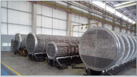
Figure 5: Heat exchanger with clad tube sheet
Moreover, Explosive welding can be used to deliver metal mixes that are difficult to accomplish with a warm welding process. Models incorporate the blend of steel (or tempered steel) with metals, for example, aluminium, titanium, zirconium and copper. It can pretty much be said that unstable welding makes it conceivable to create all metal mixes that have a full metallic bond. It can be presumed that the motivation behind dangerous welding is to lessen the cost of a bit of gear while improving its quality. Besides, the last divider thicknesses will be slenderer because of the advantage of the generally high mechanical estimations of the steel substrate. This thusly saves money on weight. Notwithstanding saving money on costly metals, lower electrical progress protections can be accomplished with separable bimetallic electrical contacts.
Metallic bond:
The welded joint delivered with the assistance of explosives depends on a metallic bond. The inquiry emerges, nonetheless, of what all things considered establishes a metallic bond. To summarize quickly, each metal exists as a aftereffect of this bond. A metallic bond is created because of valence electrons that tie metal molecules together. These valence electrons can move openly through the whole metal grid framing a shell or cloud together. This is some of the time too known as a gas haze of free electrons, which is additionally the motivation behind why a metal is ready to lead an electric flow. Normally, the molecules hold their fixed electrons around the nuclear cores, which, by definition, are called non-valence electrons. During the Explosive welding process, a ground-breaking stun drives the metal iotas into one another's range of prominence, compelling the valence electrons into each other's ways. This is basically how a metallic bond is made, the properties of which, in principle, are not mediocre compared to those of a typical metallic bond.
Explosive welding process:
So as to acquire a smart thought of the forms included, we will take the case of a carbon steel sheet which should be clad with a high-calibre metal. After the qualities of the materials to be clad have been evaluated, the sheets are deprived of their oxide layer by methods for a computerized scouring process. They are then set over each other at a particular separation utilizing plastic spacers. An edge is then fitted on top of the upper sheet which will contain the powder explosives. A detonator is connected and the entire pack is prepared for the Explosive welding process. Figure 6 gives an outline of this.
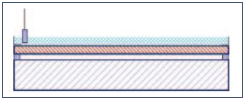
Figure 6: Illustration of set up needed for the explosive welding process
Enactment of the detonator triggers a ground-breaking Explosive that solitary keeps going a part of a second. Figure 7 gives a depiction of this procedure. Despite the fact that various hypotheses exist with respect to what really occurs during this Explosive, the sentiment beneath is by all accounts one of the generally legitimate and conceivable. The exceptionally Explosive power drives the top plate onto the base plate at a very high speed making an impact point. At the purpose of impact, the weight is so high (a few thousand bars) that the metals become super-plastic in exceptionally confined zones. There are even signs of some nuclear layers quickly going to liquid because of this huge pressure, despite the fact that the expansion in temperature is immaterial. During the Explosive, a shockwave is made which is transmitted through the two metal layers along these lines to swells in water. Because of the super plasticity of the metals in the territory of impact, the shockwave can deliver a slight wave impact in the material. This wave example can regularly be seen with the bare eye where the metals join. The high speed of this wave impact strips away any recently shaped oxides on both surfaces. This can best be contrasted with a floor covering that is shaken out mightily. The confined oxides are removed as a progression of matter only in front of the explosion front. This progression of issue is otherwise called a stream. This activity deserts clean metal surfaces which have no opportunity to oxidize, in this way permitting a metallic attach to be made. The bond is created therefore of the high weight which is as yet present what's more, which causes the valence electrons to cross into one another's circle of impact. This is the manner by which the metallic welded joint is inevitably accomplished. This welding process is otherwise called a variety of the virus pressure welding process as the whole procedure is completed at surrounding temperature. It will likewise be obvious that the air between the sheets is ousted during the cladding procedure except if this process is led in a vacuum condition.
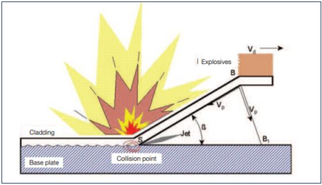
Figure 7: Explosive welding process
Advantages and Disadvantages:
Explosive welding can create a bond between two metals that can't really be welded by ordinary methods. The procedure doesn't dissolve either metal, rather plasticizing the surfaces of the two metals, making them come into private contact adequate to make a weld. This is a comparable standard to other non-combination welding systems, for example, grating welding. Huge territories can be reinforced amazingly rapidly and the weld itself is extremely perfect, because of the way that the surface material of the two metals is savagely removed during the response.
Explosive welding can join a wide exhibit of perfect and non-good metals; with in excess of 260 metal mixes possible.
A disadvantage of this technique is that broad information on explosives is required before the methodology might be endeavoured securely. Guidelines for the utilization of high explosives may require extraordinary permitting.
Underwater welding is known to individuals since 1930. It is broadly utilized for keeping up the marine foundation that is available Underwater.
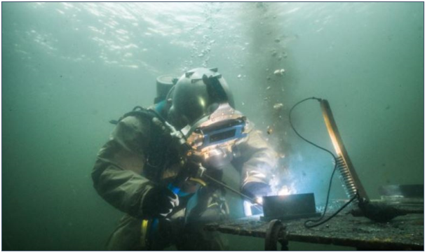
Figure 8: Underwater Welding
It is classified into two types:
Wet Welding
It is apparent that welders for the most part utilize Shielded Metal Arc Welding (SMAW) as it is the best and moderate welding strategy. Protected Metal Arc Welding is likewise called as Stick Welding. With the assistance of the Stick Welding, an electric bend is produced between the cathode and the base metal. In the majority of the cases, the base metal is frequently of copper or aluminium.
In the wet Underwater welding process (WUW), drivers must be extremely mindful and they should observe different certain principles. Here, the most significant thing that welder ought to do is keeping the anode extremely perfect.
Ordinarily, when the welders are prepared, they alert their separate group to pass the present when the cathode is in contact with the base metal.
Which sort of current is utilized during wet welding? In the wet welding process, direct current is utilized. Direct ebb and flow is more secure to use in Underwater conditions than the rotating current.
The wet Underwater welding process happens in the accompanying way:
- The work that must be welded is connected toward one side of the electric circuit while a metal cathode is joined at the opposite side.
- The electric circular segment is framed because of the provided flow. At that point, uncovered metal is welded and the arrangement of weld pool happens.
- Because of the warmth age, the cathode melts and projection of the metal beads happens into the anticipated territory. Simultaneously, the Fluxed which is covered on the cathode melts to frame the protecting gas. This protecting gas is utilized for balancing out the curve segment.
Prerequisites of the wet Underwater welding process:
Force supply: 300 to 400 amps of current. Engine generators or DC generators.
Gas manifolds
Force converter
Welding generator
Force converter
Wet Underwater welding utilizes two kinds of welding process:
1. Fluxed Cored Arc Welding (FCAW):
In the Fluxedcenter circular segment welding, a cathode is utilized for welding of compounds made up of nickel and cast iron.
2. Friction Welding (FW):
In Friction welding, contact and warmth are utilized for the liquefying of the metal.
Advantages of WUW
- Minimal effort:
The most significant advantage of the wet Underwater welding is that it is truly moderate when contrasted with the dry Underwater welding.
2. It is likewise adaptable to do
3. Brisk and Easy:
The WUW procedure is simpler to do. We can do at a quicker rate with more viability.
4. Can Weld in the Complicated Areas:
The key favourable position of wet Underwater welding is that it permits clients to weld in the confused seaward territory. Another welding procedure can't be completed effectively in the complex seaward structures.
5. Least Equipment is Required:
In the wet Underwater welding, least gear is required. A standard welding machine and a couple of different machines are required right now.
Disadvantages of Wet Underwater Welding:
- Less Strength:
The quality of the weld shaped in the wet Underwater welding is less. This is a result of fast extinguishing process. Quick extinguishing likewise influences the pliability. To put it plainly, this welding influences the quality just as the malleability.
2. Low proficiency:
As the whole procedure is done in the water. We need to confront the circumstance of poor perceivability. Because of the poor perceivability, we can't do the welding proficiently.
Dry Welding:
In the dry welding process, an exceptional sort of chamber is utilized as a welding domain. Here, the welding is done similarly as that of the normal welding process. Be that as it may, a seal-like structure is made around the zone which is to be welded. A blend of gases like helium and oxygen is available in such a territory. In the dry welding done under the water, following four dry welding techniques are utilized:
Natural surroundings Welding: In the territory welding, welders utilize the room-sized load having a similar pressure outside it.
Dry Spot Welding: Dry spot welding is generally performed for the chambers that are littler in size. Here the chamber size is as little as that of the leader of the individual. The welder needs to embed the anode inside the chamber Pressure Welding: In pressure welding, the pressure of 1 air is typically present.
Dry Chamber Welding: In the dry chamber welding, the size of the chamber is normally greater than the size of it inside the dry spot welding.
Submerged metal curve welding (SMAW) is likewise utilized in dry Underwater welding. Alongside the protected metal bend welding, the accompanying the welding procedure might be utilized here and there:
1. Plasma Arc Welding
In the plasma curve welding, an electric circular segment is utilized. Here, the exceptional warmth produced because of the created electric circular segment is utilized for welding of aluminium, treated steel and different sorts of materials.
2. Gas Tungsten Arc Welding:
Gas tungsten curve welding is likewise named as GTAW. Now and then welders additionally called it as a TIG. In the GTAW, a non-consumable cathode is utilized. A large portion of the occasions this anode is comprised of tungsten. After the arrangement of the electric circular segment, heat is created. Compounds of aluminium, tempered steel can be effectively welded with the assistance of the GTAW procedure.
3. Gas Metal Arc Welding:
Gas Metal Arc Welding is truncated as GMAW or it is otherwise called MIG welding. In the Gas Metal Arc Welding, a protecting gas is utilized. A protecting gas goes through the welding weapon. Protecting has helped in welding non-ferrous metals like aluminum.
Advantages of Dry Underwater Welding:
Wellbeing of the welder:
The dry Underwater welding is acted in the chamber in the dry condition. As water is absent in the chamber, the welder is in a protected condition. The dry zone is very much enlightened. Likewise, it has its own Environmental Control System (ECS).
That implies, there are less odds of threat to the welder while playing out the dry Underwater welding. Consequently, dry Underwater welding is useful and less perilous.
Incredible Quality Weld:
While doing welding, we generally mean to get the best weld joint. The dry Underwater welding process has an ability of creating top notch weld joints when contrasted with the outdoors weld joints. Would you be able to figure the unique purpose for the creation of the quality weld because of the dry Underwater welding?
As a matter of first importance, as the water is absent inside the chamber or during this procedure, weld doesn't get extinguished no problem at all.
The subsequent explanation is the less nearness of the hydrogen close to the weld zone.
During the dry Underwater welding (DUW), the surface can be checked no problem at all. That implies we can typically assess the joint, arrangement of the channel with no issue
Disadvantages of the Dry Underwater Welding:
Complex Habitat:
Here, we utilize a chamber as a living space. For building this chamber, a ton of complex things must be finished. Likewise, different safeguards are must be taken for making the whole natural surroundings where we can do to the welding with no issue.
Costlier Process:
The significant downside of the dry Underwater welding is that this procedure requires a ton of cash. For delivering a solitary weld, we require $80000. This sum is enormous. Likewise, a pre-owned chamber can't be reused for doing welding at various areas inside the water.
Here, the expense of the procedure is straightforwardly corresponding to the profundity of the welding zone under the water. Along these lines, on the off chance that you need to execute this welding at extremely high profundity, at that point, a huge capital must be contributed.
High Voltage Required:
At higher profundity inside the water, narrowing of the circular segment happens. More the tightening more is the voltage prerequisite.
For delivering huge voltage, greater gear. Some of the time the procedure gets difficult to direct if the voltage prerequisite is excessively enormous.
Risks of Underwater Welding:
Underwater welders are working with numerous factors like climatic pressure, water condition, diverse welding gear, electric flow thus, numerous different things. The obligation of the Underwater welder isn't that simple. They may need to look underneath threats while accomplishing their work:
Hypothermia:
Hypothermia causes when individual work in the water conditions for a long time. This can be the most well-known issue in the Underwater welders. In the event that appropriate safety measures are taken, at that point, we can without much of a stretch maintain a strategic distance from hypothermia.
Blasts:
We as a whole realize that blasts happen when hydrogen, current and oxygen gases blend in the huge sum. Along these lines, Underwater welders must be exceptionally cautious while managing the current in the enormous sum.
Metallization strategies
Physical vapor deposition (PVD):
There is an assortment of physical vapordeposition procedures. As the name
Infers, molecules/atoms (vapor) of the ideal material are legitimately deposited on to the substrate from the vapor stage. There are different PVD strategies, which differ on the how the 'vapor' is acquired. PVD is a line-of-sight deposition procedure, with the goal that the substrate must be before the source. The affidavit rate relies upon the separation between the two. The least complex PVD strategy is warm dissipation. A schematic of the procedure is appeared in Figure 14.
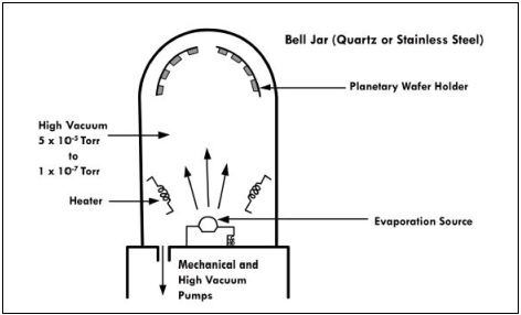
Figure 9: Thermal Evaporative Unit
The material to be vanished is warmed (by resistive warming) and the iotas are then saved on the substrate.
E-shaft dissipation, is a testimony system, where as opposed to utilizing resistive warming to frame the vapor, an electron pillar is utilized to dissolve the material what's more, structure the vapor. The e-bar dissipation source is appeared in Figure.
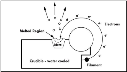
Figure 10: An e- beam Evaporative Unit
E-pillar evaporator is helpful for storing materials with high dissolving focuses like Si, Ti, W, which can't be effectively stored by warm dissipation. Both, warm dissipation and e-bar vanishing have affidavit paces of a couple A every second. For saving thick films (scarcely any hundred nm to m), sputtering is utilized. The schematic of the sputter affidavit process is appeared in Figure.
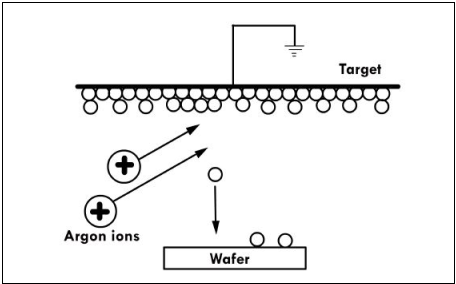
Figure 11: Schematic of Splutter deposition process
In sputter affidavit, the material to be stored is made the target terminal. This can be an unadulterated metal, amalgam or even mixes. Sputtering procedure can keep up the stoichiometry of the objective terminal, not at all like warm or e-bar dissipation. A latent gas, similar to argon, is presented in the vacuum chamber. They are ionized by utilizing an electron bar and the accelerated particles strike the objective terminal and expel material, a procedure called sputtering. In this way, the 'vapor' is made by the emphatically charged particles. The vapor molecules are then stored on the substrate. The upside of sputtering is that affidavit paces of a couple of nm for every second can be effortlessly gotten. There are three fundamental sputtering systems: DC, RF and magnetron sputtering. Their differences lies in how the Ar particles are quickened and made to strike the objective. In magnetron sputtering, attractive welds are utilized to connect the electrons before the objective to build the ionization of the Ar gas and in this manner increment affidavit rate. This additionally brings about lower chamber pressure prerequisite, making this a cleaner procedure. The schematic of the magnetron sputtering process is appeared in Figure.
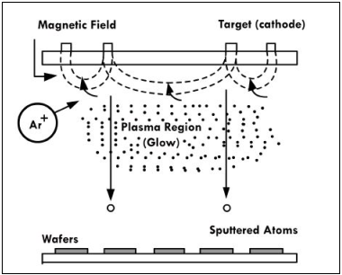
Figure 12: Schematics of magnetron sputtering process
CVD:
The CVD procedure was seen before with regards to stored lms. In metallization, CVD process is utilized for the testimony of the obstruction layer that isolates the metal from Si. This is useful for huge angle proportion structures, as appeared in Figure 14. An average response for storing tungsten is by the decrease of tungsten hexafluoride.

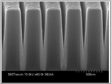
Figure 13: CVD process for growing conformal layers on deep trenches.
Electroplating:
The electroplating procedure is generally utilized for the affidavit of copper. The favourable position is the minimal effort and temperature necessities, contrasted with other vacuum statement procedures. High testimony rates can be gotten, contrasted with PVD forms. Electroplating requires a uniform seed layer.
This is gotten by sputtering and the seed layer is 30-200 nm thick. The electroplating shower is appeared in figure 15.
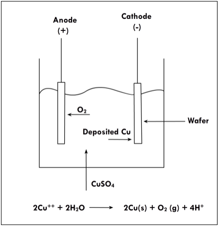
Figure 14: Schematic of Electroplating process.
The wafer, containing the seed layer, is made the cathode. The copper to be saved is the electrolyte (in the type of CuSO4). This is diminished in the shower (condition appeared in figure 15) and the Cu is then plated on the wafer surface. The procedure prompts a copper overall, making a harsh surface and the abundance material is at that point expelled by cleaning.
References:
1. P.C. Pandey and H.S. Shah, Modern Machining Processes, Tata Mcgraw-Hill Publishing Co. Ltd, New Delhi, 1980.
2. A. Ghosh and A.K. Mallik, Manufacturing Science, 2nd edition, Affiliated East West Press, New Delhi.
3. G.F. Benedict, Nontraditional Manufacturing Processes, Marcel Dekker Inc., New York (ISBN 0-8247-7352-7), 1987.
4. V.K. Jain, Advanced Machining Processes, Allied Publishers, 2009.
5. J. A. Mc Geough, Micromachining of Engineering Materials, Taylor & Francis, 2001.