Unit-3
Transformers
In a magnetic circuit, this field is represented by magnetomotive force. It is analogous to the electromotive force in electrical circuit. This field is responsible to “set up” certain flux, which in turn gives rise to certain flux density B. Note that, here H is cause and B is its effect. The amount of flux which can be setup in a material is determined by an inherent property of the material, called as permeability, denoted by µ.
B = µH
When external magnetic field H is applied to a material, all the domains align in a particular direction, setting up net flux in the material. Due to domain alignment B (i.e. the magnitude of B) increases. However, after a certain value of B, the slope of B − H curve starts reducing as shown in Figure below
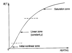
Fig: Magnetization curve
B-H Curve:
We cannot measure B and H directly. Further if we have transformer, we only have terminal measurements are with us. Hence, it is required to process the signals to get values of B and H. From Faraday’s law, V = N dφ/dt . Also, B is directly proportional to flux φ.
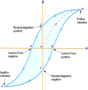
Fig: B-H curve
The lag or delay of a magnetic material known commonly as Magnetic Hysteresis. The Magnetic Hysteresis loop above, shows the behaviour of a ferromagnetic core graphically as the relationship between B and H is non-linear. Initially both B and H will be at zero, point 0 on the magnetisation curve.
If the magnetisation current, i is increased in a positive direction to some value than the magnetic field strength H increases linearly with i and the flux density B also increases (curve from point 0 to point a) as it heads towards saturation.
Now if the magnetising current in the coil is reduced to zero, the magnetic field circulating around the core also reduces to zero. However, the coils magnetic flux will not reach zero due to the residual magnetism present within the core and this is shown on the curve from point a to point b.
To reduce the flux density at point b to zero we need to reverse the current flowing through the coil. The magnetising force which must be applied to null the residual flux density is called a “Coercive Force”. This coercive force reverses the magnetic field re-arranging the molecular magnets until the core becomes unmagnetized at point c.
An increase in this reverse current causes the core to be magnetised in the opposite direction and increasing this magnetisation current further will cause the core to reach its saturation point but in the opposite direction, point d on the curve.
This point is symmetrical to point b. If the magnetising current is reduced again to zero the residual magnetism present in the core will be equal to the previous value but in reverse at point e.
Again, reversing the magnetising current flowing through the coil this time into a positive direction will cause the magnetic flux to reach zero, point f on the curve and as before increasing the magnetisation current further in a positive direction will cause the core to reach saturation at point a.
Then the B-H curve follows the path of a-b-c-d-e-f-a as the magnetising current flowing through the coil alternates between a positive and negative value such as the cycle of an AC voltage. This path is called a Magnetic Hysteresis Loop
Ideal Transformer :
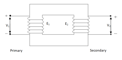
An ideal transformer has no losses i.e. its winding have no magnetic leakage and no ohmic resistance. Hence, an ideal transformer has only two purely inductive coils wound on a loss-free core.
Fig . Ideal Transformer
For above transformer when secondary is open and primary is having input sinusoidal voltage V1. An alternating current flows due to difference in potential. As primary coil is purely inductive so, Iµ current is drawn through it. This current is very small and logs V1 by 900.
The current Iµ produces magnetic flux φ and hence are in same phase. The flux is linked with both the windings and hence, self induced emf is produced E1 which is equal and opposite of V1. Similarly E2 is induced in secondary which is mutually induced emf E2 is proportional to rate of change of flux and number of secondary windings.
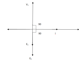
The phasor is shown below.
Phasor for Ideal Transformer
Emf Equation of Transformer :
N1 = No of primary turns
N2 = No of secondary turns
Φm = max flux in cone (wb)
Φm = Bm x A
f = Frequency of input(ac) Hz
Average rate of change of flux
= Φm / ¼
= 4ΦmF volts
Average emf per turn = 4F ΦmV
As Φ varies sinusoidally rms value of induced emf is given as
Form factor = r.m.s value / average value = 1.11
r.m.s value of emf/turn = 1.11 x 4f Φm
= 4.44 f Φm volt
r.m.s value of induced emf in primary winding
= (induced emf/turn) x No of primary turns
E1 = 4.44 fN1Φm
E1 = 4.44 fN1BmA
r.m.s emf induced in secondary
E2 = 4.44 fN2Φm
E2 = 4.44 fN2BmA
E1/E2 = N1/N2 = K
K – voltage transformation
(i). If N2> N1i.e K > 1 STEP UP TRASFORMER
(II). If N1> N2i.e K<1 STEP DOWN TRASFORMER
FOR Ideal Transformer
V1 I1 = V2 I2 = 1/K
Hence, current is inversely proportional to the voltage transformation ratio.
Transformer Equivalent Circuit :
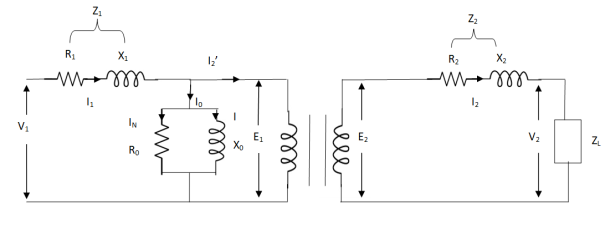
The basic transformer and its equivalent circuit both are shown below,
Fig. Equivalent Transformer Circuit
Iµ - magnetising component of current
Iw = working component
R0 – Non- inductive resistance
I0 – No load current
X0 = E1/I0. R0 = E1/Iw
E2/E1 = N2/N1 = K
E’2 = E2/K = E1
V’2 = V2/K
I’2 = K I2
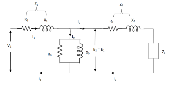
The total equivalent circuit is again given as,
But the above circuit is exact equivalent but harder to solve so, it can be further simplified as,
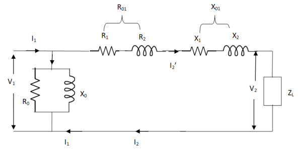
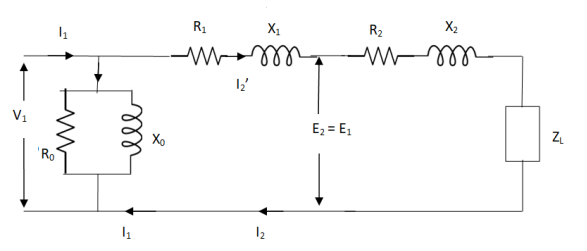
Z = Z1 + Zm || ( Z’2 + Z’L )
= Z1 + Zm(Z’2 + Z’L)/Zm + (Z’2 + Z’L)
Z’2 = R’2 + jX’2
Zm = impedance of exciting circuit
V1 = I1[ Z1 + Zm(Z’2 + Z’L) / Zm + (Z’2 + Z’L) ]
Core or Iron Loss :
This includes both hysteresis loss and eddy current loss. Iron or core loss is found from open circuit test.
Hysteresis Loss(Wh) = nB1.6max f V Watt
Eddy current Loss(We) = P B2max f2 t2 Watt
(2). Copper Loss :
This is due to ohmic resistance of the transformer windings.
Total cu loss = I21 R1 + I22 R2
= I21 R01 + I22 R02
Cu loss α I2
The value of cu loss is found from short-circuit test.
Voltage Regulation:
It can be explained in terms of various parameter of transformer.
(1). When transformer has constant primary voltage.
In this case secondary voltage decreases
0V2 = No-load secondary terminal voltage
0V2 = E2 = EK1 = KV1
V2 = secondary voltage on full-load.
Voltage Regulations is change in secondary terminal voltage from no-load to full load per unit full load voltage.
% regn down = 0V2 – V2/0V2 x 100
% regn up = 0V2 – V2/V2 x 100
(2). Voltage regulation in terms of primary values.
The secondary no-load terminal voltage as referred to primary is E’2 = E2/K = E1 = V1
For secondary full load voltage referred to primary is V’2 = V2/K
% regn = V1 – V’2/V1 x 100
% regn = I1 R01 cosφ + I1 X01 sinφ / V1 x 100
(3). As the transformer is loaded, to maintain a constant output voltage, the primary voltage should be increased. Here the regulation is given as
% regn = V’1 – V1 / V1 x 100
It can also be defined as the change in primary voltage from no-load to full-load at given power factor to maintain a constant output per unit primary voltage.
Q. A – 100 KVA transformer has 500 turns on primary and 80 turns on secondary. The primary and secondary resistances are 0.3 and 0.01 Ω respectively and the corresponding leakage reactances are 1.1 and 0.035 Ω. The supply voltage is 2400 V. Find
(i). Equivalent impedance referred to primary
(ii). Voltage regulation and the secondary terminal voltage for full load having pf 0.8 lagging?
Sol. Equivalent impedance referred to primary
Z01 = √R201 + X201 = R01 + jX01
R01 = R1 + R2/K2 = 0.3 + 0.01/K2 = 0.69 Ω
K = 80/500 = 4/25
X01 = X1 + X2/K2 = 1.1 + 0.035/(0.16)2 = 2.467 Ω
Z01 = 0.69 + j2.46
(ii). Secondary terminal voltage Z02 = K2 Z01
Z02 = 0.018 + j 0.063
= 0.065 ( 74.050
No-load secondary voltage = KV1
= 0.16 x 2400 = 384 V
I2 = 100 x 103/384 = 260.42 A
Full load voltage drop referred to secondary
= I2 (R02 cosφ– X02 Sinφ)
Cosφ = 0.8
Φ = 36.860
Sinφ = 0.6
= 260.42(0.018 x 0.8 – 0.063 x 0.6)
= - 6.094 V
% regn = -6.094/384 x 100
= -1.587
Secondary terminal voltage on-load
= 384 – (-6.094)
= 390.09 V
Efficiency:
Basically, efficiency is defined as
n = output/input
But for transformer there are small amount of losses so the improved way to find efficiency is
n = output/output + losses
n = output/output + cu loss + iron loss
Or n = Input – losses/Input
= 1 – Losses/Input
Condition for maximum efficiency :
For n to be maximum dn/dI1 = 0
(Ww) cu loss = I21 R01 or I22 R02
Iron loss = Hysteresis loss + Eddy current loss
= Wn + We = Wi
n = Input – losses/Input
Primary Input = V1I1 Cosφ1
n = V1 I1 Cosφ1 – losses/V1 I1 cos φ1
n = V1 I1 cos φ1 – I21 R01 – Wi / V1I1 cosφ1
= 1 – I1R01/V1cosφ1 – Wi/V1I1cosφ1
Differentiating w.r.t I1 both sides of above equation we have
Dn/dI1 = 0 – R01/V1cosφ1 + Wi/V1I21 Cosφ1
For max value dn/dI1 = 0
R01/V1cosφ1 = Wi/V1I21 cosφ1
Wi = I21 = I21 R01
Hence,
Wi = Wcu
Iron loss = copper loss
The value of output current for maximum efficiency will be
I2 = √Wi/R02
The maximum efficiency can also be given as,
nmax = full load x √ Iron loss / F.L .cu loss
Or
nmax = R’ x full load KVA x pf / R’ x full load KVA x pf + Wi + Wcu x 100
R’ = ratio of actual to full load KVA
Wi = iron loss (KW)
Wcu = copper loss (KW)
Q1). In a 50 KVA, 2200/200 V, 1-φ transformer, the iron and full-load copper losses are 400 W and 450 W respectively. Calculate n at unity power factor on (i). Full load (ii). Half-full load?
Sol. (i). Total loss = 400 + 450 = 850 W
F.L output at unity power factor = 50 x 1
= 50 KVA
n = 50 / 50 + .850 = 50/50.850 = 0.98 = 98%
(ii). Half full load, unity pf
= 50 KVA/2 = 25 KVA
Cu loss = 400 x (1/2)2 = 100 W
Iron loss is same = 450 W
Total loss = 100 + 450 = 550 W
n = 25/25 + 0.55 = 25/25.55 = 0.978 = 97.8 %
Q>. A 40 KVA 440/220 V, 1- φ, 50 Hz transformer has iron loss of 300 W. The cu loss is found to be 100 W when delivering half full-load current. Determine (i) n when delivering full load current at 0.8 lagging pf (ii) the percentage of full-load when the efficiency will be max.
Sol. Full load efficiency at 0.8 pf
= 40 x 0.8/(40 x 0.8) + losses
Full load cu loss = (440/220)2 x 100
= 400 W
Iron loss = 400 + 300
= 700 W
n = 40 x 0.8/(40 x 0.8) + 0.7 = 97.8 %
(ii). KVA for maximum / F.L KVA = √ iron loss / F.L cu loss
= √300/400 = 0.866
Transformers.
It is a transformer in which only one winding is common it both primary and secondary .because it has one windy it uses loss copper and is cheaper.
It can be step -up and step dawn auto transformer . The circuit for both is shown below.
Diagram:-
AB-Primary winding
BC- Secondary windings
Negating iron loss and no-load current-
 =
= =
= =K
=K
The current in CB( ) is vector difference (
 -
- )
)  >
>
An auto transformer when compared to as ordinary 2- winding transformer having same output, given higher efficiency and is smaller in size with superior voltage regulation.
FOR AUTO TRANSFORMER:
From above fig (a)& (b)
Weight of copper in AC  (N1-N2)I1
Weight of copper in BC (N2(I2-I1)
Total weight of copper  (N1-N2) I1+N2(I2-I1)
  auto transformer
For 2- winding transformer:
Weight of  on primary
  N1I1
N1I1
Weight of  on primary
  N2I2
N2I2
Total weight of  N1I1+N2I2
 =
=
=  = 1-
= 1- =1-k
=1-k
 =K ,
=K , =
=
Weight  in auto transformer =(1-k)*(weight of
  in ordinary transformer)
Saving = Wo-Wa
= W0-(1-k)W0
Saving = Kwo
Power transformer inductively =(1-k) input hence, saving will increase at K approaches unity.
Q. An auto transformer suppliers load of 4KW at 100v at unity pf. IF the applied primary voltage is 220v. Calculating power transferred to load (a) Inductively (b) conductively.
Soln, Power transferred inductively = Input(1-k)
Power transferred conductively = K* Input
K=  =
=
Input= Output =4KW
Inductively transferred power =4( )
)
=3.82KW
Conductively transferred power =  *4
*4
= 0.182 kw
Star – star or Y/Y connection: -
The below figure shows transformers connected in Y/Y on both primary and secondary sides. The ratio of line voltage and transformation ratio of line voltage and transformation ratio of both primary and secondary of each transformer in same. Hence the phase voltage VP =  . VLine (line voltage)
This connection works only if the load is balanced.
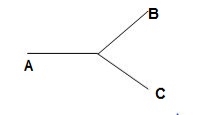
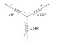
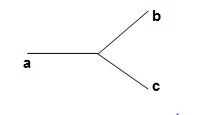
Fig: Three phase transformer Y-Y connection
- The effect of unbalanced load can be balanced by placing single load between a and n on secondary.
- Power to load is supplied by primary side A.
- As, A is in series with B and C and has b and c open on secondary, so it cannot supply required power.
- Now, B and C acts as high impedance in this condition, allowing very less flow of current in A.
- A low resistance can be connected between a and n which is approaching to short circuit. So, small current flows.
- Hence, EAN will reduce to zero but EBN and ECN will rise to full primary line voltage.
- The above shown connection is most economical for small, high-voltage transformers because the number of turns per phase and the amount of installation required is minimum.
- One more advantage is that the installation is stressed to the extent of line to neutral voltage i.e. 58% of line voltage.
- For having a sine wave voltage at output it is necessary that sine wave of flux should be in the core. To fulfil this we require third harmonic component of exciting current.
- To attain this if primary neutral is isolated then triple current cannot be attained. So, the best way is to provide a territory winding to each transformer of 1000 kVA rating.
Delta – Delta or Δ – Δ connection: -
- In this connection the ratio of transformation between both primary and secondary line voltage is same.
- There is no internal phase shift between phase and line voltages on either side as it was in Y-Y connection.
- The third harmonic component of current can flow in the Δ-connected transformer primaries.
- The balancing of load is easy unlike Y-Y connections.
- As the phases are 120˚ apart w.r.t. Third harmonic, the flux is sinusoidal which results in sinusoidal voltages.
- If anyone transformer becomes disabled. The system can continue to operate in open delta or V-V connection.
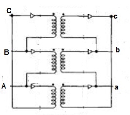
Fig: Δ-Δ connection
Wye / Delta or Y/Δ connections: -
- It is mainly used at the subtraction where the voltage is to be stopped down.
- Primary winding is Y connected and the ratio of secondary & primary line voltage is 1/
 .
. - There is 30˚Ø-shift between primary & secondary of line voltage.
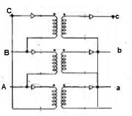
Fig: Y/Δ connection
Delta/Wye or Δ/Y connection:-
- It is used where we need to stop up the voltage.
- The primary and secondary line voltages and line currents are out of phase with each other by 30˚.
- The ratio of secondary to primary voltage is
 times of the transformation ratio of each transformer.
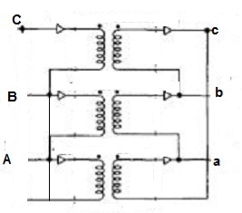
Fig: Δ-Y connection
Que 1. A 3-Ø, 50Hz transformer has delta connected primary and star-connected secondary, the line voltage being 20,000 V and 500 V respectively. The secondary has a star connected balanced load at 0.8 lagging p.f. The line current of primary side is 5A. Determine the current in each coil of the primary and secondary line. Also find the output of the transformer?
→ Phase voltage on primary side = 20,000 V
Phase voltage on secondary =  V
V
K = 
Primary phase current = 
Secondary phase current = 
= 
= 200 A
Output =  VLILcosØ
= 
= 138.56 kW
Que 2. A 100 kVA, 3Ø, 50 Hz , 3500/500 V transformer is Δ – connected on the h. V side and Y-connected on the L.V. Side. The resistance of h.V. Winding is 3.5 Ω / phase and that of L.V is 0.02 Ω per phase. Calculate the iron losses of the transformer at normal voltage and frequency if its full load efficiently be 95.1 % at 0.8 p.f. ?
→ Full load output = 100 × 0.8 = 80 kW
Input =  kW
kW
Total loss = Input – Output
= 83.2 – 80
= 3200 kW
K = 
K = 
= 
RO2 = R2 + k2R1
= 
= 0.044 Ωs
Full-load secondary phase current I2
= 
= 115.4 A
Total Cu Loss = 3I22RO2
= 3 × 0.044 × (115.4)2
= 1760 W
Iron Loss = Total loss – Cu Loss
= 3200 – 1760
= 1440 W