Unit – 9
Demonstration of a Simple Team Design Project That Illustrates
Creating Drawing Views
In previous chapters, you have learned to create multi view drawings using the standard projection techniques. Now, you will learn to automatically generate views of a 3D model.
Setting the Drafting Standard
Before you start generating the drawing views of 3D model, you need to specify the drafting standard. This defines the way the views will be generated. To specify the drafting standard, click Home > View > Drafting Standard (inclined arrow) on the ribbon; the Drafting Standard dialog appears.

In the Drafting Standard dialog, set the Projection type to Third angle.
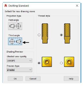
Examine the other options in the dialog, as they are self-explanatory.
Click the OK button.
Creating a Base View
Base view will be the first view of the drawing. It can be any view (front, top, right, left, bottom, back) of the model. But commonly, the front or top views of the model are generated first.
Open the Example 3.dwg, if it is not already opened.
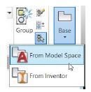
To generate the base view of the model, click Home > View > Base > From Model Space on the ribbon; the message, “Select objects or [Entire model] <Entire model>:” appears in the command line.
Select the Entire model option from the command line; the model in the model space will be selected and the message, “Enter new or existing layout name to make current or [?] <Layout1>:” appears in the command line.
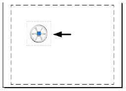
Press ENTER to select Layout 1; the base view will be attached to the pointer and the message, “Specify location of base view or [Type/sElect/Orientation/Hidden lines/Scale/Visibility] <Type>:” appears in the command line. Also, the Drawing View Creation tab appears in the ribbon.
Specify the location of the view in the paper space, as shown below.
In the Drawing View Creation tab, set the Orientation to Front.
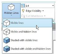
Select the Visible Lines option from the Hidden Lines drop-down.
Set the Scale in the Appearance panel to 1:4.
Click the OK button on the Create panel to create the base view; a projected view will be attached to the pointer and you will be asked to specify its location. You will learn to create projected views in the next section.
Press ENTER to exit the command.
Creating a Projected View
A projected view can be created from an existing view. It can be an orthographic view or isometric view generated by projecting from a base view or any other existing view.
To create a projected view, click Layout > Create View > Projected on the ribbon, and then select the base view from the Layout 1; the projected view will be attached to the pointer.
Move the pointer downward and specify the location of the projected view, as shown below.
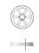
Move the pointer diagonally toward top-right corner and place the isometric view as shown below.
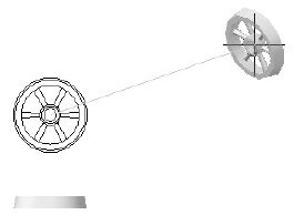
Select the exit option from the command line to exit the command.
A 3D wireframe model is an edge or skeletal representation of a real-world object.
3D wireframe models consist of points, lines, arcs, circle, and other curves that define the edges or center lines of objects.
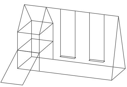
You can use a 3D wireframe model to
Generate basic 3D designs for evaluation and fast design iterations
View the model from any viewpoint
Analyze spatial relationships, including the distances between corners and edges, and checking visually for potential interferences
Generate perspective views (not available in AutoCAD LT)
Generate standard orthographic and auxiliary views automatically
Act as reference geometry for 3D solid, surface, and mesh modeling
It's strongly recommended that you keep 3D wireframe geometry on a separate reference layer for convenient access when checking the integrity of a 3D model or for recreating portions of it.
Methods for Creating 3D Wireframe Models
Wireframe modeling requires practice and experience. The best way to learn how to create wireframe models is to begin with simple models before attempting models that are more complex.
You can create wireframe models by positioning any 2D planar object anywhere in 3D space, using the following methods:
Enter 3D coordinates that define the X, Y, and Z locations of the defining points of an object.
Set the default work plane, which is the XY plane of the UCS, on which to create planar objects such as an arcs or circles.
Move, copy, or rotate the object to its 3D location after you create it.
Note: You can use the XEDGES command to create wireframe geometry from regions, 3D solids, surfaces, and meshes. The extracted edges form a duplicate wireframe composed of 2D objects such as lines, circles, and 3D polylines. (This feature is not available in AutoCAD LT.)
The Extrusion button on the Mesh task dialog is active only when the following conditions are met:
Automatic Sizing has been invoked
One or more extrudable parts have been selected.
An extrudable part contains the following attributes:
A uniform cross-section
The topology of the part must be invariant in the extrusion direction. For a part to be extrudable, it must have the same cross-section in at least one direction. If a part consists of an extrudable region connected to another region with a different cross section, the part is not extrudable:
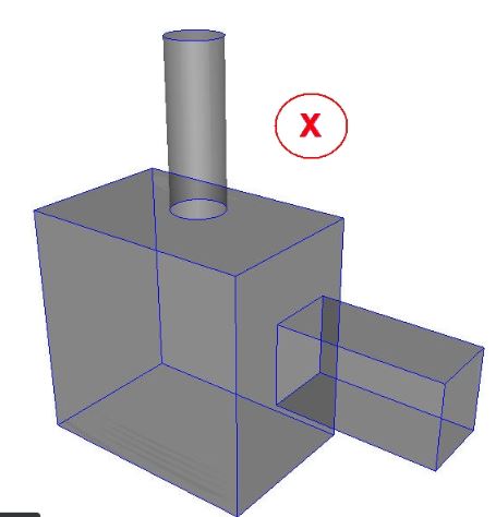
In this example, because all three regions are in the same part, the part is not extrudable. The pipe and channel protruding out from the box would be extrudable if they were separate parts forming an assembly.
Linear extrusion path
Only parts that have a linear extrusion path are eligible for extrusion. Parts that bend, even if the cross section is uniform, are not extrudable:
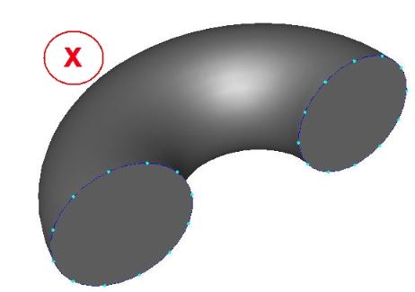
Three dimensional
Only three-dimensional parts are supported by extrusion. Two dimensional surfaces in 2D analyses must be free meshed.
Uniform surfaces in at least one extrusion direction
It is not possible to extrude in a direction if edges on a surface are normal to that direction:
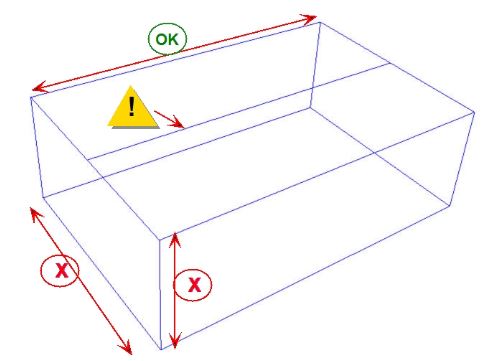
During the manufacturing process, the accuracy of a part is an important factor. However, it is impossible to manufacture a part with the exact dimensions. Therefore, while applying dimensions to a drawing we provide some dimensional tolerances, which lie within acceptable limits. The following example shows you to add dimension tolerances in AutoCAD.
Geometric Dimensioning and Tolerancing
Earlier, you have learned how to apply tolerances to the size (dimensions) of a component. However, the dimensional tolerances are not sufficient for manufacturing a component. You must give tolerance values to its shape, orientation, and position as well. The following figure shows a note which is used to explain the tolerance value given to the shape of the object.
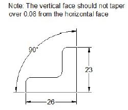
Providing a note in a drawing may be confusing. To avoid this, we use Geometric Dimensioning and Tolerancing (GD&T) symbols to specify thetolerance values to shape, orientation, and position of a component. The following figure shows the same example represented by using the GD&T symbols. In this figure, the vertical face to which the tolerance frame is connected, must be within two parallel planes 0.08 apart and perpendicular to the datum reference (horizontal plane).
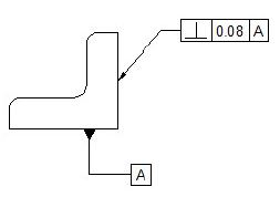
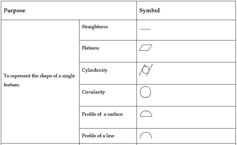
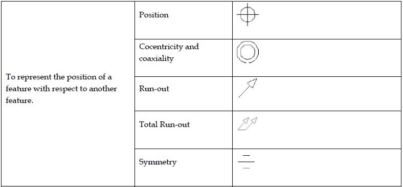
The Geometric Tolerancing symbols that can be used to interpret the geometric conditions are given in the table below.

There are two ways of creating any assembly model.
• Top-Down Approach
• Bottom-Up Approach
Top-Down Approach
The assembly file is created first and components are created in that file.
Bottom-Up Approach
The components are created first, and then added to the assembly file. In this tutorial, you will create the assembly using this approach.
Starting a New Assembly File
To start a new assembly file, click the Assembly icon on the Home screen.

Inserting the Base Component
1. To insert the base component, click Assemble > Component > Place on the ribbon.
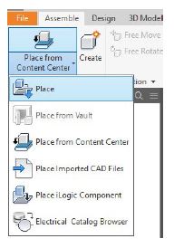
2. Browse to the project folder and double-click on Flange.ipt.
3. Right-click and select Place Grounded at Origin; the component is placed at the origin.
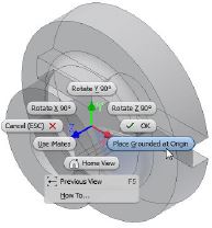
4. Right-click and select OK.
Adding the second component
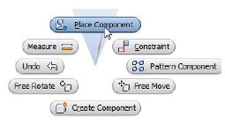
1. To insert the second component, right-click and select Place Component; the Place Component dialog appears.
2. Browse to the project folder and double-click on Shaft.ipt.
3. Click in the window to place the component.
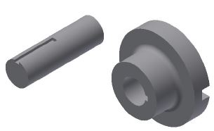
4. Right-click and select OK.
Applying Constraints
After adding the components to the assembly environment, you need to apply constraints between them. By applying constraints, you establish relationships between components.
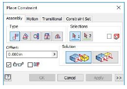
1. To apply constraints, click Assemble > Relationships > Constrain on the ribbon.

The Place Constraint dialog appears on the screen.
References: