Unit – 1
Introduction
Drawings convey the following information: -
Engineering drawing is the basic need to develop the design and assembly of a machine, the three necessary techniques of drawing/projection are:
Building Drawing.
Types of Building Drawing.
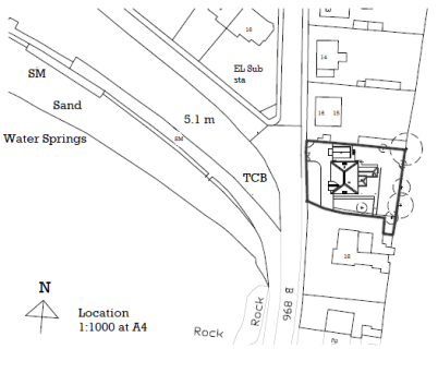
1. Site Plan.
2. Line Plan.
3. Detailed Plan.
4. Foundation Plan.
5. Landscape plan.
6. Elevation.
7. Sectional Elevation.
8. Perspective Drawing.
9. Submission drawing
10.Model
When you work in a layout, the scale factor of a view in a layout viewport represents a ratio between the actual size of the model and the size of the layout.
This ratio is determined by dividing the paper space units by the model space units
You can change the view scale of the viewport by using
Note:
Annotative Objects and Scaling
It is defined at a paper height instead of a model size and assigned one or more scales. These objects are scaled based on the recent annotation scale setting .The annotation scale controls the size of the annotative objects relative to the model shape in the drawing.
Scale drawing
Scale drawings are used to illustrate items that it is not useful or convenient to draw at their actual size
A distance at full size: The distance at the scale used that would be the same length.
For example:
In the construction industry a range of scales are available
For example:

THE ORIGINS OF CAD/CAM
Advantages of CAD:
1. Save’s time: It can make better and more systematic designs in shorter time duration.
2. Easy to edit: it will be much easier and safer to make any changes because you can fix the errors and modify the drawings easily.
3. Decrease in error percentage: the percentage of error that occurred because of manual designing is decreased.
4. Decrease design effort: It has been reduced significantly because the software brutalise most of the task.
5. Easy to share: It makes easier to save the files and store it in a way that you can use it time and again.
6. Improved accuracy: The fact that the kind of accuracy that CAD software will offer can never be achieved by opting for manual drawings. You have tools to measure the precision, skill and accuracy level of the designs.
Disadvantages of CAD:
AutoCAD drawing file can be identified by its X, Y, Z coordinates or WCS i.e., World Coordinate System
Coordinate input
Draw by numbers
It define absolute X, Y coordinates with respect to the 0,0 point of the drawing — usually, its lower-left corner...
Data is defined in both horizontal and vertical coordinate systems. Horizontal coordinate systems locate data cover the surface of the earth, and vertical coordinate systems locate the elevation or depth. Horizontal coordinate systems can be of three types: geographic, projected, or local
Reference Work Planes
It is defined as a plane on the face of the extents of a modifier. Every modifier has an unseen extent, or boundary box, that defines the extents of the feature
These are the various ways of a reference plane, example of each one:
Before we make a drawing, we make many settings in the blank file like changing Units, Limits, Adding Layers, Line types, Blocks Dimension styles etc and it is not always empirical to duplicate the settings.
To make it easier, we can make a drawing template in AutoCAD. Templates are saved with DWT file extension and saved file work in a template file it gets saved as a DWG file.
Setting Drawing Units
The precision is simply the precision up to which AutoCAD will display the decimal places. Irrespective of the precision format
In the “Units to scale inserted content” dropdown change the value to Inches, this is the Unit which will be displayed in the drawing
In the Angle panel change type to Decimal Degrees, we can change it to other angle formats as well from the drop-down menu. Change the precision from Angle drop-down menu to 0.00
Click OK to save these changes and close the Drawing Units window.
Understanding Units representation
When Architectural length type is selected in the Units window, we can use apostrophes symbol to specify the drawing units like (‘) for feet and (“) for inches. For example, if you want to make a line of length 5 feet and 6 inches then you can enter its length as 5’6” on the command line.
If you are using Decimal length format instead of Architectural then feet and inches symbol will return an error. For example, to make a line of length 1’4” simply type 16 for its length (1’=12”) without any apostrophes.
Setting drawing limits
We need to specify the extents of the working area of the drawing. All the drawings are not made on a single scale as an example a large floor plan of an Hall would take a lot of space and its dimensions will be in the range of many feet and if you are making a simple watch gear then the dimensions should remain in the scale of a few millimeters.
we will make a simple drawing which has maximum dimensions of 10 feet in length and width. So, to make it we will define a drawing area of 15 feet in length and width keeping 5 feet margin.
Type LIMITS and press enter. Command line will prompt “Specify lower left corner or [ON/OFF] <0′-0″,0′-0″>:” simply press enter to accept the default values of the lower left corner which is 0,0.
On the next step “Specify upper right corner <1′-0″,0′-9″>:” type 15’,15’ and press enter.
To apply the changes type Z and press enter then type A and press enter again. This will reset your drawing area.
Now the height of your drawing area is 15 inches and the length of the drawing area will be 15 inches.
This limit value is not a permanent value and you can alter the limits by zooming in or out of your drawing.
Creating drawing Template
Now click on save and click OK when description box opens. The template will be saved on the desktop with dwt file extension. You can now open your drawing with this template simply by double-clicking on the My Template file on the desktop.
Opening drawing with no templates
If you don’t want to use any preinstalled or custom template to start your drawing moreover you want to open the drawing with the blank properties then there is an option for that too. Click on the “New” icon on the quick access toolbar or use command NEW.
The drawing template window will open. Click on the arrow right next to the open button and select “open with no template”.
The drawing aids in the AutoCAD program are like the triangles, compasses, and engineering scales of traditional drafting.
ENTITIES: It is the main section of a drawing file and contains the actual characteristic Each characteristic contains standard information, such as its colour, layer, line style, and geometry.
In a drawing you can create a variety of different entity types. Drawing entities can be very simple such as lines, circles, arcs, points and rays or complex such as polylines, splines and planes.
To create an entity you can choose between selecting the command in the Draw menu, using the tools on the Draw
When you use a tool or a drawing command, the program box open to enter coordinate points, such as endpoints or insertion points. You can enter the points or distances either using a mouse or by typing coordinate values in the command bar
New entities are made on the current layer, using the current colour, line type and line weight.
Modify Panel is used for the editing of any existing drawing.
| 19. Erase (E+Enter) 20. Offset (O+Enter) 21. Array (AR+Enter) 22. Explode 23. Lengthen 24. Break (BR+Enter) 25. Break at point 26. Join (J+Enter) 27. Edit Hatch 28. Edit Array 29. Edit Polyline (PEdit+Enter) 30. Edit Spline 31. Move (M+Enter) 32. Rotate (RO+Enter) 33. Copy (CO+Enter) 34. Mirror (M+Enter) 35. Stretch
|
Essential Commands of Modify Panel in AutoCAD
Move (M+Enter): -
We can move any objects at a specified distance and direction.
Process of using move command: -
Rotate (RO+Enter): -
We can rotate any selected object around a base point to an angle.
It rotates any objects in clock and anti-clockwise.
Process of using Rotate command: -
Copy (CO+Enter): -
It is used to copy an object at a specified distance or direction. It works almost like Move Command.
Process of using Copy command: -
Mirror (MI+Enter): -
It creates a reverse copy of the selected object.
Process of using mirror command: -
Stretch: -
In these, one can move some part of drawing with carrying the connection with other parts.
Process of using Stretch command: -
Scale (SC+Enter): -
We one can enlarge or reduce the objects. The length and width of objects would be enlarged or reduced at the same size.
Process of using Scale command
Trim (TR+Enter+Enter): -
It is used to trim any objects whose edge meet the other objects. It trims the crossed line.
Process of using Trim Command: -
Extend (EX+Enter): -
It helps to extend the line to join the edges of other objects line. It is used as a trim command.
Process of using Extend command: -
Or
2. Type LAYER at the command prompt.
Command: LAYER (or LA)
Or
3. Pick the layers icon from the Layer Control box on the object properties toolbar.


2. In the Dimension Style Manager, select the style you want to change. Click Modify.
3. In the Modify Dimension Style dialog box, Text tab, under Text Appearance, select a text style.
4. If the current text style does not have a fixed height, enter the height of dimension text in the Text Height box.
5. Under Tolerances, enter a height for tolerance values in the Scaling for Height box.
6. In the Offset from Dim Line box, enter a value for the gap around base dimension text.
7. Select a colour from the Text Colour box.
8. Click OK.
Create dimension objects
|
Draw horizontal or vertical linear dimensions. |
|
Draw a linear dimension lined up with two points. |
|
Dimension the angle between two lines. |
|
Dimension the area of a closed curve, surface, mesh, or hatch. |
|
Dimension the length of a curve. |
|
Dimension the diameter of a curve. |
|
Dimension the x or y distance from a base location. |
|
Dimension the radius of an arc or circle. |
|
Draw a linear dimension that is rotated from the xy axis. |
|
Dimension the angle between two planes. |
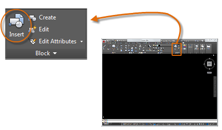
Insert a Block
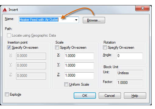
Each of these blocks is an individual drawing file, saved in a folder with similar drawing files. When you need to insert one into your current drawing file, you use the INSERT command

The first time you insert the drawing as a block, you need to click Browse to locate the drawing file.

Once inserted, the block definition is stored in your current drawing.
Named Objects for Standards-Checking
Standards File
Define standards, save them as standards file then associate the standards file with one or more drawing files. After you associate a standards file with a drawing, you should check the drawing to make sure it confirms with the standards.
How a Standards Audit Works
Check a drawing for standards violations, each named object of a specific type is checked against the standards files linked with the drawing.
A standards audit can uncover two types of problems:
Example: -you fix a nonstandard layer, WALL, and replace it with the standard ARCH-WALL. In this example, choosing Fix in the Check Standards dialog box transfers all objects from layer WALL to layer ARCH-WALL and then purges layer WALL from the drawing.
Standards Plug-Ins
The auditing process uses standards plug-ins, define the rules for the properties that are checked for individual named objects.
All plug-ins check all properties for each named object except for the layer plug-in.:
The following layer properties are not checked by the layer plug-in:
References:
1. Subhash C Sharma & Gurucharan Singh (2005), “Civil Engineering Drawing”, Standard Publishers
2. Ajeet Singh (2002), “Working with AUTOCAD 2000 with updates on AUTOCAD 200I”, Tata- Mc Graw- Hill Company Limited, New Delhi
3. Sham Tickoo Swapna D (2009), “AUTOCAD for Engineers and Designers”, Pearson Education
4. Venugopal (2007), “Engineering Drawing and Graphics + AUTOCAD”, New Age International Pvt. Ltd.
5. Balagopal and Prabhu (1987), “Building Drawing and Detailing”, Spades publishing KDR building, Calicut
6. (Corresponding set of) CAD Software Theory and User Manuals.
7. Malik R.S., Meo, G.S. (2009) Civil Engineering Drawing, Computech Publication Ltd New Asian. Sikka, V.B. (2013), A Course in Civil Engineering Drawing, S.K.Kataria& Sons.


