Unit - 2
Friction
Basically, force of friction can be broadly classified into the following types:
Static Friction
Dynamic Friction, which is further subdivided as Sliding and Rolling friction
Fluid Friction
As we know friction is force of resistance offered to external forces coming onto the system. Hence, the types of forces of friction that might be present are as mentioned above.
In solid surfaces, static, sliding and rolling friction are present. Static type of friction is always strongest than all others, which is then followed by sliding friction, and then by rolling type of friction, which is weakest of all above.
Fluid friction is present in case of fluid contact, like liquids and gases. E.g., Flow of water or fluid through the pipe.
Some of the other types of friction, depending upon the type of application may be as:
Lubricated friction is a type of fluid friction present in between the surface of material and lubricating fluid layer present.
Skin friction is a type of drag present between the two surfaces in contact during the motion of a body over a surface.
Internal friction is type of force of resistance present in a body during any deformation of that body taking place.
In case of Static friction, the two surfaces in contact are at rest. This is shown in figure below.
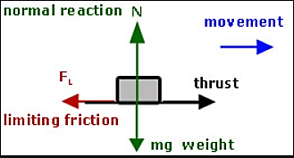
Thus, according to the Newton’s First Law of Motion, any object tends to be in rest or motion, unless an external unbalanced force is applied on it. Thus, in this case, if two surfaces are in static condition, there is no unbalanced force acting on them. Now, if small amount of force is applied on the block, as shown in the figure as movement, then in absence of friction, the block should move. But as friction is present, the block will stay in rest condition. Now, we will start increasing the applied force in the form of movement shown in fig. till the point when the movement applied by external force overcomes the friction present. Thus, the minimum value of force that needs to be applied to make the block move from its rest condition, is called as limiting friction. When the applied force exceeds the limiting friction value, block will start to move.
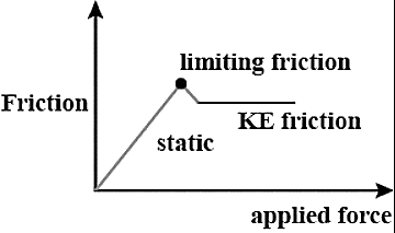
Thus, the value of limiting friction is maximum, compared to static and KE friction depicted in graph shown.

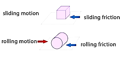
The coefficient of friction given for all the mentioned cases will follow the laws of friction mentioned below.
Coulomb friction is also known as Dry friction and was named after C. A. Coulomb who extensively studied this phenomenon. Dry friction is considered to exist between the two surfaces of objects which are in contact when there is absence of any kind of fluid lubrication.
Dry friction may take place either due to adhesion between the surfaces, or roughness or contamination of surfaces taking place.
As there is loss of mechanical energy in the form of heat during the frictional process, it turns out to be non-conservative force that is path dependent.
The force of friction is always applied in a manner that opposes the movement created within the two surfaces. Any object moving on a road or any surface slows down and then eventually stops.
Dry friction is can be further classified into static friction which is between non-moving surfaces, and kinetic friction which is between moving surfaces.
The laws are discussed as:
Laws of Static Friction:
Following are the laws of static friction:
1. The force of friction always act in direction which is opposite to motion of body.
2. The magnitude of force of friction is equal to the force acting on the body externally.
3. There is constant ratio between limiting frictional force and the normal reaction forces. Mathematically:
(F/R) = Constant
where F = Limiting friction, and R = Normal reaction.
4. The force of friction does not depend on the area of contact between the two surfaces.
5. There is dependency of frictional force on roughness of the surfaces.
Laws of Kinematic or Dynamic Friction:
Following are the laws of kinetic or dynamic friction:
1. The force of friction always act such that it opposes the motion of body.
2. There is a constant ratio between kinetic motion and normal reaction. But this ratio is slightly less when it comes to limiting friction.
3. For medium speeds, the force due to friction stays constant. But it decreases somewhat when the speed increases.
e.g., 1: The uniform crate shown in Fig. below has a mass of 20 kg. If a force P = 80 N is applied to the crate, determine if it remains in equilibrium. The coefficient of static friction is  = 0.3.
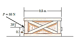
Solution:
The first step is free-body diagram i.e.
Free-Body Diagram. As shown in Fig. diagram below, the resultant normal force NC acts at a distance of x from the centre line of crate for countering the tilting effect caused by P. Hence, there are three unknowns, F, NC and x, which can be solved by equations of equilibrium.
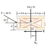
Equations of equilibrium:
Σ Fx = 0
80 cos 30° N - F = 0
Σ Fy = 0
-80 sin 30° N + NC - 196.2 N = 0
Σ M = 0
80 sin 30° N10.4 m2 - 80 cos 30° N10.2 m2 + NC (x) = 0
Thus, solving the above equations, we get,
F = 69.3 N
NC = 236 N
x = -0.00908 m = -9.08 mm
As value of x is negative, hence it acts to left of centre line of the crate. There will be no tipping since x < 0.4 m. Fmax =  Nc = 0.3(236 N) = 70.8 N. Since F that we got is 69.3 N < 70.8 N, the crate will not slip.
For understanding motion of bodies, using friction, we will discuss two types of motion.
When the object is lying onto the surface, without any inclination, horizontally.
When the surface is inclined at an angle with the horizontal.
Thus, in first case for solving problems related to dry friction and motion of bodies, when the surface is horizontal, we follow the steps mentioned below.
Free-Body Diagrams:
Draw the necessary free-body diagrams, and unless it is stated in the problem that impending motion or slipping occurs, always show the frictional forces as unknowns (i.e., do not assume  ).
).
Initially find the number of unknowns and then compare with the available equations of equilibrium.
If unknowns are more than equations available, then frictional equation is also considered.
If the equation  is to be used, it will be necessary to show F acting in the correct sense of direction on the free-body diagram.
Equations of Equilibrium and Force of Friction.
Apply the equations of equilibrium and the necessary frictional equations (or conditional equations if tipping is possible) and solve for the unknowns.
Cartesian Vectors can be used if there is three-dimensional figure and it becomes difficult to solve it.
The steps mentioned above can be used for solving the numerical related to dry friction, and the surface being horizontal which are explained below.
e.g., 2: A body of weight 300 N is lying on a rough horizontal plane having a coefficient of friction as 0.3. Determine the magnitude of the force, which is needed to move the body, acting at 25° by the horizontal.
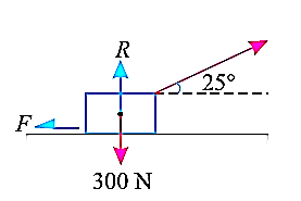
Solution:
Given:
Weight of the body (W) = 300 N; Coefficient of friction (μ) = 0.3 and
angle made by the force with the horizontal (α) = 25°
Let P = Magnitude of the force, which can move the body, and
F = Force of friction.
Initially, we will solve the problem in horizontal direction as,

The next step is to resolve the force in vertical direction, we get,


The force of friction (F) is given as,


Hence, P = 87.1 N.
e.g., 3: A body, which is positioned on a rough horizontal plane, needs a pull of 180 N inclined at 30° to the plane just for moving. Also, it was found that a push of 220 N which is inclined at 30° to the plane also moved the body. Find out the weight of the body and the coefficient of friction present here.

Solution:
Given: Pull = 180 N; Push = 220 N and angle at which force is inclined with horizontal plane (α) = 30°
Let W = Weight of the body
R = Normal reaction, and
μ = Coefficient of friction.
First of all, consider a pull of 180 N acting on the body. We know that in this case, the force of friction (F1) will act towards left as shown in Fig. (a).
Resolving the forces horizontally,
F1 = 180 cos 30° = 180 × 0.866 = 155.9 N
and now resolving the forces vertically,
R1 = W – 180 sin 30° = W – 180 × 0.5 = W – 90 N
We know that the force of friction (F1),
155.9 = μR1 = μ (W – 90)
Now consider a push of 220 N acting on the body. We know that in this case, the force of friction (F2) will act towards right as shown in Fig. (b).
Resolving the forces horizontally,
F2 = 220 cos 30° = 220 × 0.866 = 190.5 N
and now resolving the forces horizontally,
R2 = W + 220 sin 30° = W + 220 × 0.5 = W + 110 N
We know that the force of friction (F2),
190.5 = μ.R2 = μ (W + 110) ...(ii)
Dividing equation (i) by (ii)
155.9 W + 17 149 = 190.5 W – 17 145
34.6 W = 34 294
W = 991.2 N
Now substituting the value of W in equation (i),
155.9 = μ (991.2 – 90) = 901.2 μ
μ = 0.173
In this way, numerical based on dry friction can be solved.
In the second case, when the surface makes some angle with the horizontal, the formula used can be derived as,
Let’s find out the minimum force that will keep the block in equilibrium and avoid sliding downwards.
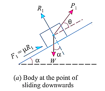
W is the Weight of the body,
α is the between the inclined plane and horizontal
θ is the angle between the force applied and inclined surface,
R is the normal reaction,
μ is the coefficient of friction and
φ is angle of friction, such that  .
.
When we resolve the forces along the inclined plane, we will get,

Similarly, when we resolve the forces vertically,

Now, solving the two equations, we get,


Thus,

Here, if we substitute,  we get,

Then, if we multiply and divide by cos , we get,

Now, for maximum force that will keep the body in equilibrium and not slide upwards can be determined in similar manner.
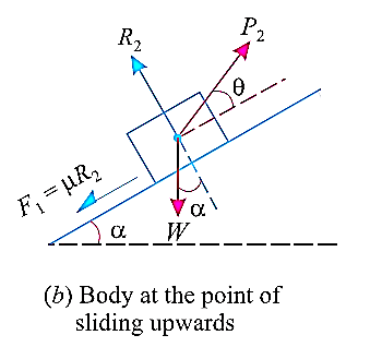
Resolving the forces shown in fig. above along the inclined plane.

Now, resolving in direction perpendicular to the plane,

Then,


Thus,

Here, if we substitute,  we get,

Then, if we multiply and divide by cos , we get,

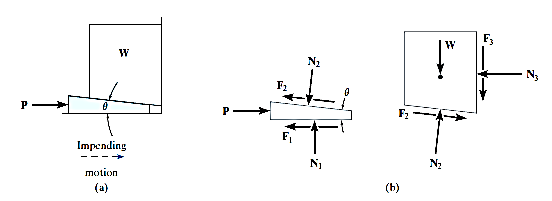
A Wedge can be considered as a simple device, that is used to transform or slightly adjust heavy loads and their positions, when the load is supported at right angles to its surface. Consider, for example, the wedge shown in Fig. (a), which is used to lift the block by applying a force to the wedge. Free-body diagrams of the block along with wedge shapes are shown in Fig. (b). Here we have excluded the weight of the wedge since it is usually small compared to the weight W of the block. Also, note that the frictional forces F1 and F2 must oppose the motion of the wedge.
Likewise, the frictional force F3 of the wall on the block must act downward so as to oppose the block’s upward motion. Hence the moment equilibrium equations will not be considered. There are seven unknowns, consisting of the applied force P, needed to cause motion of the wedge, and six normal and frictional forces. The seven available equations consist of four force equilibrium equations,  Fx = 0,
  Fy = 0 applied to the wedge and the block, and three of the frictional equations, F =
  N, applied at each surface of contact.
If the block is to be lowered, then the frictional forces will all act in a sense opposite to that shown in Fig. (b). Provided the coefficient of friction is very small or the wedge angle  is large, then the applied force P must act to the right to hold the block. Otherwise, in order the block, P may have reverse direction. If without application of P, block is held with the help of frictional forces, then the wedge is referred to as self-locking.
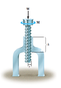
In most cases screws are used as fasteners; however, in many types of machines they are incorporated to transmit power or motion from one part of the machine to another. A square threaded type of screw can be used when large amount of forces is to be transmitted along the axis of the screw. In this section we will analyze the forces acting on square-threaded screws. The analysis of other types of screws, such as the V-thread, is based on these same principles.
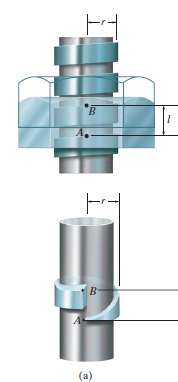
For the purpose of analysis, a square threaded screw, as in Fig. below, can be considered a cylinder having an inclined square ridge or thread wrapped around it. If we unwind the thread by one revolution, as shown in Fig., the slope or the lead angle  is determined from
  = tan-1(l/2πr). Here l and 2πr are the vertical and horizontal distances between A and B, where r is the mean radius of the thread. The distance l is called the lead of the screw and it is equivalent to the distance the screw advances when it turns one revolution.
Upward Impending Motion: Let us now consider the case of a square-threaded screw that is subjected to upward impending motion caused by the applied torsional moment M, Fig. below. A free-body diagram of the entire unraveled thread can be represented as a block as shown in Fig. above. The force W is the vertical force acting on the thread or the axial force applied to the shaft, Fig. below, and M/r is the resultant horizontal force produced by the couple moment M about the axis of the shaft. The reaction R of the groove on the thread, has both frictional and normal components, where  . The angle of static friction is
  = tan-1(F/N) = tan-1
 . Applying the force equations of equilibrium along the horizontal and vertical axes, we have
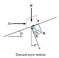
Σ Fx = 0
M/r - R sin ( +
+  ) = 0
) = 0
Σ Fy = 0
R cos ( +
+  ) - W = 0
Eliminating R from these equations, we obtain
M = rW tan ( +
+  )
)
Self-Locking Screw: A screw is said to be self-locking if it remains in place under any axial load W when the moment M is removed. For this to occur, the direction of the frictional force must be reversed so that R acts on the other side of N. Here the angle of static friction  becomes greater than or equal to
  , If
, If  then R will act vertically to balance W, and the screw will be on the verge of winding downward.
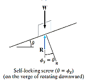
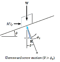
Downward Impending Motion: ( If a screw is self-locking, a couple moment M’ must be applied to the screw in the opposite direction to wind the screw downward
  .This causes a reverse horizontal force M’/r that pushes the thread down as indicated in Fig. below. Using the same procedure as before, we obtain
M’ = rW tan ( )
)
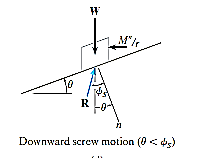
Downward Impending Motion:  . If the screw is not self-locking, then there is need for applying a moment M” for preventing the screw from winding downward. Here, a horizontal force M”/r is required to push against the thread to prevent it from sliding down the plane, Fig. below. Thus, the magnitude of the moment M” required to prevent this unwinding is
M– = Wr tan ( )
)
References:
1. Irving H. Shames (2006), Engineering Mechanics, 4th Edition, Prentice Hall
2. F. P. Beer and E. R. Johnston (2011), Vector Mechanics for Engineers, Vol I - Statics, Vol II, – Dynamics, 9th Ed, Tata McGraw Hill
3. R. C. Hibbler (2006), Engineering Mechanics: Principles of Statics and Dynamics, Pearson Press.
4. Andy Ruina and Rudra Pratap (2011), Introduction to Statics and Dynamics, Oxford University Press
5. Shanes and Rao (2006), Engineering Mechanics, Pearson Education