Unit - 3
Basic Structural Analysis
A system of forces is said to be in equilibrium if the resultant force which is summation of all the forces acting on the body is zero. If we consider in Static Equilibrium, then the system is considered to be in rest condition. Thus, for a system to be in rest condition, it needs to satisfy the Newton’s First Law of motion. Thus, the generalized equation for a system to be in equilibrium states that resultant force acting on the system should be zero for the system to be in equilibrium,
i.e.,  .
.
This is further explained in the topic of equations of equilibrium for the system.
For any three-dimensional force system, as shown in Fig. below, we can resolve the forces into their respective i, j, k components, so that
Σ Fx i + Σ Fy j + Σ Fz k = 0
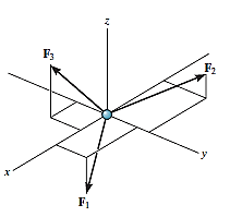
To satisfy this equation we require,
Σ Fx = 0
Σ Fy = 0
Σ Fz = 0
These three equations state that the algebraic sum of the components of all the forces acting on the particle along each of the coordinate axes must be zero. Using these equations mentioned we can solve for maximum three of the unknowns, shown by coordinate direction angles or magnitudes of forces shown on the particle’s free-body diagram.
For solving three-dimensional problem, we can use the following procedure.
Free Body Diagram:
• In any orientation, establish x and y axes.
• Then mark all the known and unknown forces in figure.
• Unknown forces are also assumed and plotted.
Equations of Equilibrium.
• Apply the equations of equilibrium, Σ Fx = 0, Σ Fy = 0 and Σ Fz = 0.
• Initially we can display as a Cartesian vector if it becomes to solve the problem regularly, substitute these vectors into Σ F = 0 and then set the i, j, k components equal to zero.
• If the resultant comes out to be negative value, it means that the direction needs to be reversed for that is already considered.
Problems in Three-dimensions:
e.g., 3: The 10-kg lamp in Fig. below is suspended from the three equal-length cords. Find the smallest vertical distance s from the ceiling if force built in cord is not to go beyond 50 kN.
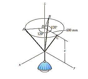
Solution:
For solving these three-dimensional numerical, we will follow the same procedure mentioned above.
Free-Body Diagram: Because of symmetry, the distance are as  mm. It follows that from Σ Fx = 0 and Σ Fy = 0, the tension T in each cord will be the same. Also, the angle between z axis and every cord is
  .
.
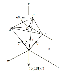
Equation of Equilibrium: Applying the equilibrium equation along the z-axis, with T = 50 N, we have
Σ Fz = 0;
3[(50 N) cos  ] - 10(9.81) N = 0
 = cos-1 (98.1 / 150)
= 49.160
Now,
By geometry shown in free-body diagram,
tan 49.160 = (600 / s)
s = 519 mm
In this way, three-dimensional problems are solved using equations of equilibrium.
e.g., 4: A 90-lb load is being suspended from a hook as shown in Fig. below. If the load is being supported by two cables and a spring having a stiffness of k = 500 lb/ft, find the force in the cables and the stretch of the spring for equilibrium. Cable AD lies in the x–y plane and cable AC lies in the x–z plane.
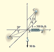
Solution:
Initially, force in spring is determined to determine stretching of spring.
Free-Body Diagram. A point is chosen for all analysis as all the points are concurrent here. The free-body diagram for the problem is shown in Fig. below.
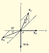
Equations of Equilibrium. We can resolve each force in x, y and z components, and so we can use three scalar equations of equilibrium. Considering components directed along each positive axis as “positive,” we have
Σ Fx = 0
FD sin 30° - (4/5) FC = 0
Σ Fy = 0
-FD cos 30° + FB = 0
Σ Fz = 0
(3/5) FC – 90 lb = 0
Thus, solving the above-mentioned equations, we get,
FC = 150 lb
FD = 240 lb
FB = 207.8 lb
The stretch of the spring is therefore
FB = ksAB
207.8 lb = (500 lb/ft) (sAB)
sAB = 0.416 ft


The procedure for solving is same as that of the particle equilibrium, just we need to consider the additional degree of freedom to be locked.
For solving simple truss example using method of sections, we will follow the below procedure.
Make a cut in section where forces are to be determined.
Initially determine support reactions.
Draw the free-body diagram of that segment of this type of truss which is sectioned with minimum forces.
Unknown member forces can be found by above mentioned methods.
Moments should be summed about a point that lies at the intersection of the lines of action of two unknown forces, so that the third unknown force can be determined directly from the moment equation.
If two of the unknown forces are parallel, forces may be summed perpendicular to the direction of these unknowns to determine directly the third unknown force.
The basic ideology for using this method is that, if a structure is in equilibrium, then all the joints of its members will be in equilibrium.
Hence, using free body diagram, and using force equilibrium equations we can determine the forces acting on each member at various joints. As discussed earlier, the members of truss are considered to be coplanar and meeting at a point, i.e., concurrent, we can use the conditions of coplanarity equilibrium discussed earlier, like  and
and  .
.
For solving simple truss example using method of joints, we will follow the below procedure.
Draw the free body diagram which minimum one known and 2 unknown forces.
Use one of the two methods described above for establishing the sense of an unknown force.
Draw x and y axed such that we can easily solve for x and y components and then apply the two force equilibrium equations and Solve for the two unknown member forces and verify their correct sense.
The two assumptions mentioned above, i.e., loads should be applied at joints and members should be connected with smooth pins, have made each member to act as a two-force member. Thus, due to the assumptions mentioned, each member will be as shown in fig.
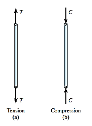
Thus, the force acting on each and every member will be directed such that it will be along the axis of the member itself. If because of this force, the length of member increases or member elongates, then the type of force acting on member will be tensile as shown in fig. (a). If due to the force, if the length of member decreases, i.e., the member shortens, then the type of force acting on member will be compression, as shown in fig.(b). In this way, we can determine whether a particular member is in tension or compression.
Simple truss problems can be solved using two methods:
Thus, the methods mentioned above are discussed below:
Truss:
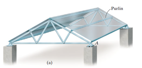
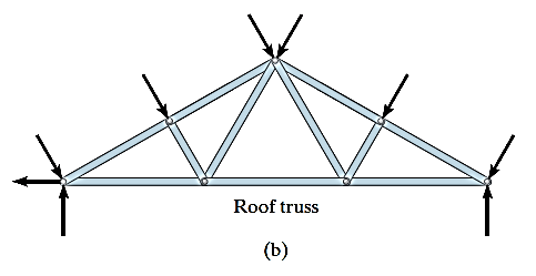
A truss is a structure which is made of slender members those are joined together at the end points. Planar trusses lie in one single plane and these are frequently used to support some of the bridges and roofs. Fig. (a) is a typical roof-supporting truss used for construction. Since this loading turns in the similar plane as the truss, Fig. (b), the analysis of the forces developed in the truss members will be two-dimensional.
Now, for understanding the considerations made during solving of truss problems, let us understand by the following example:
Let us consider a bridge, as shown in the fig. below.
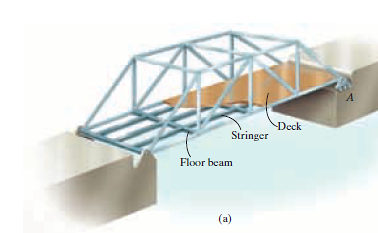
Here, the load is transmitted from the Deck to the Stringer, as shown in fig. Then, from Stringer, the load gets transmitted to Floor Beam. From the floor beam, the load is transmitted to the joints that holds the bridge, i.e., Side Truss. Thus, we understand that the side truss will be coplanar, as shown below (b).
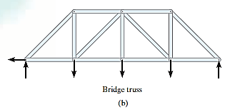
If the span is larger, then for accommodation of thermal expansion or compression of members of bridge, rollers or rockers are used that is shown in above fig. (a), point named as A.
Thus, while design of such kind of truss, we mention some of the assumptions.
Mostly, the loads applied in case of bridges or trusses is at joints only, hence this assumption is mostly true. But, if the weight of an object is to be considered, then the weight is supposed to be applied at each end point of the member and half in magnitude of its original magnitude in the form of vertical force.
2. The members should be joined using smooth pins:
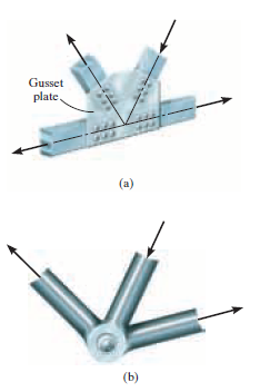
As shown in the fig. above, most of the members are considered to be joined using bolting or welding method to a gusset plate, fig.(a), or by directly putting a bolt through the endpoints as shown in fig.(b). This will be true if the members of truss and bolt applied are concurrent.
Frames are the type of structures which are often composed of pin-connected multi-force members, i.e., members that are subjected to more than two forces. Frames are used to support loads.
The process for solving problems of plane frames is as discussed below.
Draw the free-body diagram of the entire frame or machine, a portion of it, or each of its members. The choice should be made so that it leads to the most direct solution of the problem.
When the free-body diagram of a group of members of a frame or machine is drawn, the forces between the connected parts of this group are internal forces and are not shown on the free-body diagram of the group.
Forces common to two members which are in contact act with equal magnitude but opposite sense on the respective free-body diagrams of the members.
Two-force members, regardless of their shape, have equal but opposite collinear forces acting at the ends of the member.
In many cases it is possible to tell by inspection the proper sense of the unknown forces acting on a member; however, if this seems difficult, the sense can be assumed.
Remember that a couple moment is a free vector and can act at any point on the free-body diagram. Also, a force is a sliding vector and can act at any point along its line of action.
Count the number of unknowns and compare it to the total number of equilibrium equations that are available. In two dimensions, there are three equilibrium equations that can be written for each member.
Sum moments about a point that lies at the intersection of the lines of action of as many of the unknown forces as possible.
If the solution of a force or couple moment magnitude is found to be negative, it means the sense of the force is the reverse of that shown on the free-body diagram.
References:
1. Irving H. Shames (2006), Engineering Mechanics, 4th Edition, Prentice Hall
2. F. P. Beer and E. R. Johnston (2011), Vector Mechanics for Engineers, Vol I - Statics, Vol II, – Dynamics, 9th Ed, Tata McGraw Hill
3. R. C. Hibbler (2006), Engineering Mechanics: Principles of Statics and Dynamics, Pearson Press.
4. Andy Ruina and Rudra Pratap (2011), Introduction to Statics and Dynamics, Oxford University Press
5. Shanes and Rao (2006), Engineering Mechanics, Pearson Education