Unit - 1
Introduction to Surveying
The two-fundamental principle upon which various methods of plane surveying falls are:
Location of a point by measurement from two points of reference
The relative position of a point to be surveyed is located by measurement from at least two points of reference, the positions of which have already been fixed.
If P and Q are the two reference points on the ground, any other point, such as R, can be found by any of the direct methods. A single method is sufficient to locate the relative position of ‘R’ with respect to reference points P and Q, it is necessary to adopt at least any two methods to fix the position of point ‘R’.
Working from whole to part
Here it is always desirable to carryout survey work from whole to part which means, when an area is to be surveyed then first a system of control points is to be established covering the whole area with very high precision. Then small details are located by less accurate methods.
The idea of working this way is to prevent the accumulation of errors and to control and localize minor errors which would expand to greater magnitudes if the reverse process is followed, thus making the work uncontrolled at the last.
Linear surveying involves measurement of distances between points on the surface of the earth.
Methods of Linear Surveying
Linear surveying involves measurement of distances between points on the surface of the earth. There are various methods of linear surveying and their relative merit depends upon the degree of accuracy required
Linear surveying methods can be divided into three:
1.Direct Measurement
In this surveying method, distances are measured on the surface of the earth by use of chains, tapes, etc.
2.Measurement by Optical Means
In this method, observations are taken through a telescope and distances are determined by calculation as in tachometer or triangulation.
3.Electronic Methods
Here distances are calculated with instruments that rely on propagation, reflection and subsequent reception of either radio or light waves. The various instruments that are used under the electronic methods are
(i) geodimeter,
(ii) tellurometer,
(iii) Decca navigator, and
(iv) lambda position fixing system.
The distance measured in the case of geodimeter is based on the propagation of modulated light waves. The other three instruments use radio waves for distance measurement.
1.3.1 Angular Method
There are 2 methods of angular survey which are: -
1.Triangulation survey
Triangulation is a surveying method which measures angle in a triangle formed by # survey control points by using trigonometry.
2.Traverse survey
The survey where number of connected survey lines from framework and direction length of survey lines are measured with the help of angle measuring tools.
1.3.2 Graphical Method
Graphical Method
In these angles and lengths are determined and represented it on a graph which determines the location of plane table.
The Two-Point Problem
In the two-point problem, two points are sighted from other point corresponding to the points given in plane table sheet. Here two cases are to be discussed.
Case 1: when the points can be occupied by the plane table
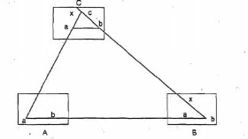
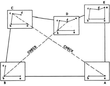
As shown in fig. A and B are the two points corresponding to the points a and b. Now, plane table is located at B and oriented by sighting A. sight C from B and bx is plotted on the sheet. Then shift the plane table to C, oriented by back sighting B along xb. Then alidade is placed over a and sight station A, then line Aa cuts the line bx at somewhere which is located as point cat station C.
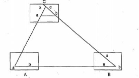
Case2: When the plane table cannot occupy the controlling stations
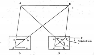
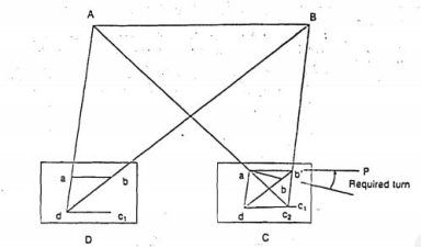
In this case, an auxiliary point D is considered nearer to C. Locate the plane table at D according to the line ab parallel to AB. Then sight the station A and B corresponding to a and b. the rays drawn are intersected at some point which is marked as d. then sight towards C by placing alidade at d. mark the distance Dc as c1. Shift the table to C and back sight to D with reference to c1.
Then sight A corresponding to a, the ray drawn is intersects the previously drawn ray from D in c2. From c2 sight B draw a ray which intersects db and marked the intersection as b1. The table is oriented till ab comes in line with P. From P sight and draw rays Aa and Ba. The intersection of these two rays will give the Location of Point C.
Three Point Problem
three points and their positions in the field are known. Plane table is placed at a position from where all the three points are visible. So, by sighting those three points we can locate the point where equipment is located. This can be achieved by following methods
Tracing Method in Plane Table Surveying
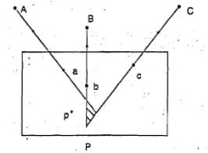
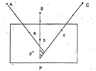
Here plane table is located at a point from where three points are visible. The table is oriented with respect to the plotted lines of those three points. Place the tracing paper on the drawing sheet and again sight the three points and plot the radiating lines. The tracing paper is then moved above the drawing sheet until the three radiating lines pass through corresponding points previously plotted on the map and then the position of plane table is marked.
Lehmann Method
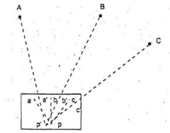
Here the Plane table is located at a point P and sight the station A, B and C and plot the rays Aa, Bb, and Cc. The rays form small triangle are called triangle of error. Another point P1 is chosen to reduce the error and sight the point A from P1 similarly to B and C. which will give another triangle of error. Repeat this procedure until error becomes 0.
Survey stations are the points at the start and the end of a chain line. They may also happen at any convenient points on the chain line. Such station may be:
1. Main stations.
2. Subsidiary stations. And
3. Tie stations.
Main Stations.
The stations taken along the boundary of an area as controlling points are known as ‘main stations. The lines joining the main stations are called ‘main survey lines.
Subsidiary Stations.
The stations are on the main survey lines or any other survey lines are known as “subsidiary station”. These stations are taken to run subsidiary lines for dividing the area into triangles, for checking the accuracy of triangles and for locating interior details.
Tie Stations.
Tie stations are also subsidiary stations taken on the main survey lines. Lines joining the tie stations are called tie lines. Tie lines are mainly taken to fix the directions of the adjacent sides of the chain survey map.
Base Line.
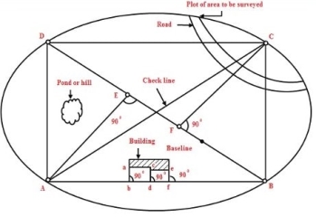
The line on which the framework of survey is formed is known as the ‘base line’. It is most important line of the survey. The longest of the main survey lines is considered the base line. This line should be taken through fairly level ground, and should be measured very carefully and accurately.
Check Line.
The line joining the apex points of triangle to some fixed point on its base is known as the ‘check line’. It is taken to check the accuracy of the triangle.
Bearing of a line is the horizontal angle which a line makes with some reference direction also known as meridian.
Important definition
Reduced level: -elevation of any point with respect to mean sea level.
Benchmark: -a fixed point on ground of known reduced level from where levelling work is started and reduced level of all other points are calculated with respect to reduced level of benchmark.
Back sight: -first reading taken after setting up the instrument at any location.
Foresight: -all least readings taken from any instrument location.
Intermediate sight: -all other staff readings other than back sight/foresight
Height of instrument: -reduced level of line of sight at any location of instrument.
H.I.=RL of B.M. +B.S.
R.L. of next point=H.I.-F.S./I.S.
1.5.1 Survey Lines
It is a line produced on a cast by a surveyor marking the contour in relation with planned path of placement of a restoration is known as survey line.
Chain lines
the lines joining the main stations are called main Survey or Chain lines
Base Line.
The line on which the framework of survey is formed is known as the ‘base line’. It is most important line of the survey. The longest of the main survey lines is considered the base line. This line should be taken through fairly level ground, and should be measured very carefully and accurately.
Check Line.
The line joining the apex points of triangle to some fixed point on its base is known as the ‘check line’. It is taken to check the accuracy of the triangle.
1.5.2 Ranging
It is the process of establishing intermediate point on a straight line between two end points.
There are two methods of ranging.
1) Direct ranging.
2) Indirect ranging or reciprocal ranging
The horizontal angle between the reference meridian and the survey line is called as bearing of the survey line.
Magnetic bearing:
The magnetic needle of the compass always points towards the magnetic north-south (N-S) direction indicating earth’s magnetic axis. Since this direction is same at all the places on the earth’s surface, it is universally used as the reference direction. The angle made by survey line in a clockwise direction with reference to magnetic N-S line is called as magnetic bearing of the line. The value of magnetic bearing ranges from 0 to 360o.
True Bearing:
geographical north of earth is different from the magnetic north. Hence the angle which the survey line makes with the true geographical north is called as true bearing of the survey line.
Arbitrary Bearing:
It is the horizontal angle which a survey line makes with any arbitrary meridian, which is any convenient direction towards permanent signal, such as a church and chimney etc
Whole circle Bearing (WCB):
The complete circle of angular measurement starts with north as 0 o and ends at north at 360o. The bearing of line directly obtained by magnetic needle ranging from 0 o to 360 o is called whole circle bearing.
Reduced Bearing (RB):
The more convenient way to comprehend the direction of a survey line is to represent the bearing on a quadrantal system. The angle is measured with respect to N–S line towards east or west.
Fore Bearing (FB):
Angle measured in the direction of survey line from starting survey station to the next station is called for bearing.
Back Bearing (BB):
It is the bearing of the survey line taken from the forward survey station to the preceding station from which the fore bearing was taken earlier. In Figure, if the bearing of same line AB is measured from B towards A, it is known as backward bearing or back bearing.
Height of Instrument method
In this method, the height of the instrument (H.I) is measured for each setting of the instrument by adding back sight (plus sight) to the elevation of the B.M. The elevation of (Reduced Level) the turning point is then calculated by subtracting fore sight from H.I. For the next setting of the instrument the H.I. is obtained by adding the B.S taken on TP1 to it RLs
Check
∑B.S – ∑F. S = Last RL – First R
There are two Methods of Levelling:
1. Height of collimation system
2. Rise and fall system
Height of collimation system
1. rapid Calculation.
2. no check for the RL in the intermediate sight.
3.Errors in the intermediate RLs cannot be find out.
4. two checks are there for the accuracy of RL calculation
5.This system is suitable for longitudinal levelling where number of intermediate sights
Rise and fall system
1. It is laborious process of calculation.
2.There is a check on the RL of the intermediate points
3.error can be detected in intermediate RLs
4. three checks are present for the accuracy of RL calculation.
5.this method is used for fly i.e., when there is no intermediate sights.
This is the fast method of surveying. In this type of surveying plotting of the plan and field observations can be done parallel. In case of plane table surveying Geometrical conditions of site are manuscript in the map sheet using plane table and alidade after that topographic details are arranged on the map.
Equipment Used in Plane Table Survey
General equipment used for conducting plane table survey are
Plane table survey equipment is arranged in 4 steps as follows
Fix the plane table to the tripod stand. Arrange the drawing sheet on the plane table using paper clips or thumb screws. The sheet should be in one position from first to last.
II. Levelling of Plane Table
Plane table can be levelled using spirit level. For small works, eye estimation can be ok.
III. Cantering of Plane Table
The table should be cantered by using plumbing fork from which we can arrange the plotted point exactly over the ground point.
IV. Orientation of Plane Table
Whenever we are using more than one instrument station, orientation is necessary. It can be done by using compass or back sighting. Here the plane table is rotated such that plotted lines in the drawing sheet are parallel to corresponding lines on the ground.
Methods of Plane Table Surveying:
Generally, there are four methods available to perform plane table surveying. They are
Radiation
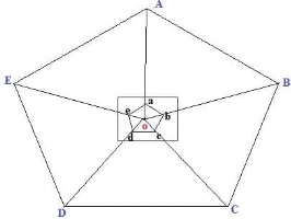
In this method, plane table is located at one point “o” and perform the whole from that point. From point O, sight the points A, B, C, D and E using alidade, locate and plot the points as a, b, c, d and e in the drawing sheet.
Intersection
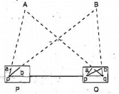
In this method we can locate the point by plotting two rays from two known stations. As shown in figure, P and Q are the known station. First the equipment is placed on P and plot the lines by sighting the stations A, B and Q. then shift the equipment to station Q and plot the lines by sighting stations A, B and P. Finally, the intersection of A and B rays is the required location of point of intersection.
Traversing
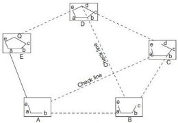
Traversing is the connection of series of straight lines. In case of traversing, plane table is located at one-point A as shown below. From here point sight towards B and measure the distance AB.
Then shift the plane table to point B and sight towards A and measure BA. Average distance of AB and Ba are plotted to scale in drawing sheet. Then Sight the point C from B and measure BC and repeat the same procedure until last point. Conduct some checks at some points. Finally, traverse lines are plotted on drawing sheet.
Resection
Resection is a method of plane table surveying in which location of plane table is not known and it is determined by sighting it to known points or plotted points. It is also called method of orientation and it can be conducted by two field conditions which are:
Three Point Problem
Three points and their positions in the field are known. Plane table is placed at a position from where all the three points are visible. So, by sighting those three points we can locate the point where equipment is located. This can be achieved by following methods
Tracing Method in Plane Table Surveying
Here plane table is located at a point from where three points are visible. The table is oriented with respect to the plotted lines of those three points. Place the tracing paper on the drawing sheet and again sight the three points and plot the radiating lines. The tracing paper is then moved above the drawing sheet until the three radiating lines pass through corresponding points previously plotted on the map and then the position of plane table is marked.
Lehmann Method
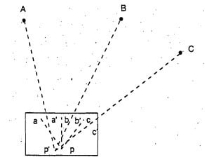
Here the Plane table is located at a point P and sight the station A, B and C and plot the rays Aa, Bb, and Cc. The rays form small triangle are called triangle of error. Another point P1 is chosen to reduce the error and sight the point A from P1 similarly to B and C. which will give another triangle of error. Repeat this procedure until error becomes 0.
Analytical Methods
There are many analytical methods are developed in three-point problem condition. In this method, from station P A, B and C are sighted and the values of angles and lengths are noted.
Graphical Method
In these angles and lengths are determined and represented it on a graph which determines the location of plane table.
The Two-Point Problem
In the two-point problem, two points are sighted from other point corresponding to the points given in plane table sheet. Here two cases are to be discussed.
Case 1: when the points can be occupied by the plane table
As shown in fig. A and B are the two points corresponding to the points a and b. Now, plane table is located at B and oriented by sighting A. sight C from B and bx is plotted on the sheet. Then shift the plane table to C, oriented by back sighting B along xb. Then alidade is placed over a and sight station A, then line Aa cuts the line bx at somewhere which is located as point c at station C.
Case2: When the plane table cannot occupy the controlling stations
In this case, an auxiliary point D is considered nearer to C. Locate the plane table at D according to the line ab parallel to AB. Then sight the station A and B corresponding to a and b. the rays drawn are intersected at some point which is marked as d. then sight towards C by placing alidade at d. mark the distance Dc as c1. Shift the table to C and back sight to D with reference to c1.
Then sight A corresponding to a, the ray drawn is intersects the previously drawn ray from D in c2. From c2 sight B draw a ray which intersects db and marked the intersection as b1. The table is oriented till ab comes in line with P. From P sight and draw rays Aa and Ba. The intersection of these two rays will give the Location of Point C.
Surveying based on Type of Instruments
a) Chain Surveying
Chain surveying is the basic type of surveying. The principle involved in chain survey is of triangulation. The area to be surveyed is divided into a number of small triangles. Angles of triangles must not be less than 30 degree and greater than 120 degree. Equilateral triangles are known to be ideal triangles. No angular measurements are taken, tie line and check lines control accuracy of the work.
This method is suitable on level ground with little undulations and area to be survey is small.
b) Compass Surveying
Compass survey uses the principle of traversing. This method does not require the need to create triangles. It uses a prismatic compass for measuring magnetic bearing of line and the distance is measured by chain. A series of connecting lines is prepared using compass and measuring distances using chain. Interior details are located using offset from main survey lines.
They suitable for large area surveying crowded with many details. It can be used to survey a river course.
c) Plane Table Surveying
The principle of plane table survey is parallelism. They are plotted directly on paper with their relative position. The rays are drawn from station to object on ground. The table is placed at each of the successive station parallel to the position of the last station.
They are basically suitable for filling interior detailing and is recommended when great precision is not required.
d) Theodolite Surveying
The theodolite is an instrument used mainly for accurate measurement of the horizontal and vertical angles. They are accurate to measure up to 10″ or 20″ angles.
Theodolite can be used to measure:
Nowadays theodolite is shadowed and replaced by the use of Total Station which can perform the same task with greater ease and accurate results
e) Tachometric Surveying
Tachometry is a branch of surveying in which horizontal and vertical distances are determined by taking angular observations with an instrument called tacheometer. Tacheometer is nothing but a transit theodolite fitted with a stadia diaphragm and an analytic lens. There is no need for chaining in such survey. The principle of Tacheometer is based on property of isosceles triangle, where ratio of the distance of the base from the apex and the length of the base is always same.
Different form of stadia diaphragms commonly used:

f) Photographic Surveying
Photographic survey is based on technique of taking photographs from different angle to prepare topographic details with relative high speed.
There are two types of photographic surveying
i). Terrestrial or ground photogrammetry
In terrestrial photogrammetry maps are prepared from ground photographs from different points on the earth surface for measurement purpose.
ii). Aerial photogrammetry
In aerial photogrammetry maps are produced from air from an airplane or helicopter.
Photogrammetry encompasses two major area of specialization.
Metrical photogrammetry is of principal interest to surveyors as it is applied to determine distances, elevations, areas, volume, etc. to compile topographic maps made from measurements on photographs.
Intuitive photogrammetry involves objects from their photographic image and their significance. Critical factors considered in identifying object of shape, sizes, patterns, shadow.
When the level is set up correctly and levelled the line of collimation will be horizontal telescope is rotated about is its vertical axis the it will revolve in a horizontal plane known as the plane of collimation and therefore, all staff’s readings taken with the will be the vertical measurements made downwards from this plane.
To find by how much amount the line of sight is above the bench mark and to ascertain by how much amount the next point is below or above the line sight.
Height of instrument= Elevation of B.M + Back sight Elevation of pt B = Height of instrument – Foresight
There are two methods of working out the reduced levels of the point from the staff readings taken in the field:
1. Height of Instrument or Collimation Method.
2. Rise and Fall Method.
1. Height of Instrument or Collimation Method.
It helps in finding the elevation of the plane of collimation i.e. (H.I.) for every setting of the instrument and then getting the reduced levels of the points with reference to the respective plan of collimation
To start with, the H.L is calculated by adding the back sight of the R.L. of the starting point. The reduced levels of the intermediate point and the first change point are then obtained by subtracting the respective readings from the H.I. When the instrument is shifted, a new plane of collimation is set up and the height of which is calculated by adding back sight reading to the R.L. of the first change point.
establishing elevations is the most essential activity of the field engineer. Elevations are needed to set slope stakes, grade stakes, footings, anchor bolts, slabs, decks, sidewalks, curbs, etc.
Differential levelling is a very simple process based on the measurement of vertical distances from a horizontal line. Elevations are transferred from one point to another through the process of using a levelling instrument to read a rod held vertically on, first, a point of known elevation and, then, on the point of unknown elevation. Simple addition and subtraction are used to calculate the unknown elevations.
A back-sight reading is taken on a rod held on a point of known elevation. That elevation is transferred vertically to the line of sight by reading the rod and then adding the known elevation and the backsight reading. The elevation of the line of sight is the height of instrument (HI), the line of sight is horizontal; therefore, the line-of-sight elevation can then be transferred down to the unknown elevation point by turning the telescope to the foresight and reading the rod. The elevation of the foresight station is found by subtracting the rod reading from the height of instrument. The difference in elevation from the backsight station to the foresight station is determined by subtracting the foresight rod reading from the backsight rod reading.
If the level is placed exactly midway between two points and staff reading are taken to determine the difference of level then an error is automatically eliminated but here in the case of a river or valley, it is not possible to set up the level midway between two points on the opposite bank so, the method of reciprocal levelling is adopted.
In reciprocal levelling, the level is set up on both bank of the river or valley and two sets of staff reading is taken by holding the staff on both banks in this case it is found that error is completely eliminated and true difference of level is equal to the mean of the two apparent differences of level.
Procedure:
1. Suppose A and B are two points on an opposite bank of a river. The level is set up very near A and after proper temporary adjustment staff reading are taken at A and B. suppose reading a1 and b1
2. Level is shifted and set up very near B and after proper adjustment, staff reading is taken as A and B. Suppose the reading are a2 and b2
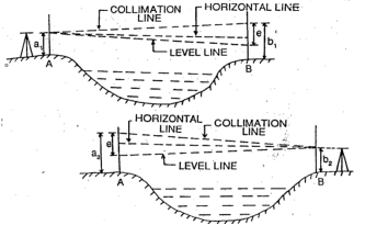
Let,
h= true difference of level between A and B
e= combine error due to curvature, refraction and collimation
(Error is +ve and –ve, here error is assumed +ve)
First case:
Correct staff reading A=a1
Correct staff reading B=b1 – e
True difference of level between A and B
h= a1 – (b1-e) ……………………………………………………..eq.1
Second case:
Correct staff reading B=b2
Correct staff reading a=a2 – e
True difference of level between A and B
h= (a2 - e) – b2 ……………………………………………………..eq.2
from (1) and (2)
2h= a1 – (b1-e) + (a2 - e) – b2
2h= a1 – b1 + e + a2 – e – b2
2h= (a1 – b1) + (a2 – b2)
h= [(a1 – b1) + (a2 – b2)] / 2
Levelling
Levelling may be defined as the art of determining the relative height or elevates of points or objects on the earth’s surface.
Instruments used for levelling:
Level
Levelling Staff
Level: The purpose of a level is to provide a horizontal line of sight.
Parts:
A telescope to provide line of sight
A level tube to make the line of sight horizontal
Levelling head to bring the bubble in its centre of run
A tripod to support the instrument
Dumpy level:
The telescope is fixed with the support and therefore, can neither be rotated about the longitudinal axis, or can it be removed from its support. A long bubble tube is attached at the top of the telescope. The levelling head generally consists of two parallel plates with either three-foot screw of four-foot screws. The upper plate is known as tribrach and the lower plate is known as trivet which can be screwed on a tripod
Levelling staff:
A levelling Staff is a straight rectangular rod having graduations, the foot of the staff representing zero reading.
One is Folding type of 4m Levelling Staff:
It consists of two wooden pieces each of 2m of length with the joint assembly. The thickness and width of staff are respectively 18m and 75mm. The folding joint is of the detachable type with locking device at the back.
Hence the stand can be made into two parts for easy handling. When two pieces are locked together, the two pieces form a straight rigid levelling staff of length equal to 4m.
Profile levelling is the most common applications of running levels and vertical distance measurement for the surveyor. The results are plotted in the form of a profile, which is a drawing that shows a vertical cross section. Profiles are required for the design and construction of roads, curbs, sidewalks, pipelines, etc Profile levelling refers to the process of determining the elevation of points on the ground at mostly uniform intervals along a continuous line.
Equipment used for profile levelling
Procedure for profile levelling
Longitudinal levelling
Profile levelling is the same as benchmark levelling, with one difference. At each instrument position, where an HI is determined by a back sight rod reading on a benchmark or turning point, several additional foresight readings may be taken on as many points as desired. These additional readings are called rod shots, and the elevation of all those points is determined by subtracting the rod shot from the HI at that instrument
Location.
The profile drawing is basically a graph of elevations, plotted on the vertical axis, as a function of stations, plotted on horizontal axis. A gridded sheet called profile paper is used to plot the profile data from the field book. All profile drawings must have a proper title block, and both axes must be fully labelled with stations and elevations.
The elevation or elevation scale is typically exaggerated; that is, it is ‘stretched’ in comparison to the horizontal scale. For example, the vertical scale might be 10 times larger. The horizontal line at the bottom of the profile does not necessarily have to start at zero elevation
1.11.1 Cross sectioning levelling
Cross sectioning levelling is another method in profile levelling. The term cross-section generally refers to a relatively short profile view of the ground, which is drawn perpendicular to the route centreline of a highway or other types of linear projects.
Cross-sectional drawings are particularly important for estimating the earthwork volumes needed to construct a roadway, they show the existing ground elevations, the proposed cut or fill side slopes, and the grade elevation for the road base. =
There is really no difference in procedure between profile and cross-section levelling except for the form of the field notes. Cross-section rod shots are usually taken during the route profile survey from the same instrument positions used to take rod shots along the centreline.
Cross-section data are obtained at the same locations along the route that are used for the profile rod-shot stations.
Digital levelling systems for surveying rely on an electronic laser to scan a level staff with bar code markings. This type of level reduces the chance of human error when interpreting graduation marks, and a digital display ensures accurate readings. When job sites need fast and accurate height determinations, precision digital levelling equipment serves as valuable time-saving technology.
An upside to digital levels is the potential for data integration. A surveyor can store readings in the internal memory and refer to them later, or transfer data to computers using external memory ports. Contractors should be aware that digital levels require a battery, which is often rechargeable, to operate.
1.12.1 Auto Levels
Auto levels are the most common instruments on construction sites today. In place of vertical staff with a bar code, auto level instruments require conventional graduations of inches or centimeters.
When using auto-levelling systems for surveying, setup time reduces because of an internal swinging prism inside the equipment. This suspended piece inside the telescope tilts from the slope of the earth underneath as long as the tripod base is placed safely, gravity performs most of the work levelling the instrument, and the three screws allow for finer adjustment by the user. These compact pieces of equipment increase productivity for surveyors because of the speed at which they can be prepared to measure at different points.
There are following types of Errors in Levelling: -
1. Instrumental error and Correction
- Correction: Check before use and equalise sights.
- Correction: Check
- Correction: Permanent adjustment.
- Correction: Permanent adjustment
2. Error of Collimation
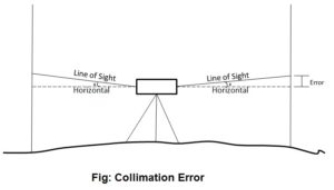
Collimation error occurs when the collimation axis is not truly horizontal when the instrument is level. The effect is illustrated in the sketch below, where the collimation axis is tilted with respect to the horizontal by an angle a.
3. Curvature & Refraction
Curvature of the earth:
The earth appears to “fall away” with distance. The curved shape of the earth means that the level surface through the telescope will depart from the horizontal plane through the telescope as the line-of-sight proceeds to the horizon.
This effect makes actual level rod readings too large by:

where D is the sight distance in thousands of feet.
Effects of Curvature are:
Atmospheric Refraction:
Refraction is largely a function of atmospheric pressure and temperature gradients, which may cause:
the bending to be up or down by extremely variable amounts.
The atmosphere refracts the horizontal line of sight downward, making the level rod reading smaller. The typical effect of refraction is equal to about 14% of the effect of earth curvature.
Combined Effect of Curvature and Refraction in Survey
The combined effect of curvature and refraction is approximately

The formula for computing the combined effect of curvature and refraction is:
C + R = 0.021K2
Where C = correction for curvature
R = correction for refraction
K = sighting distance in thousands of feet
4.Other sources of errors in levelling and their correction:
Type of Error | Correction |
1. Incorrect setting-up of instrument. |
|
2. Movement of staff from position when changing level station. |
|
3. Staff not held vertically. |
|
4. Parallax: Instrument knocked or moved during backsight-foresight reading |
|
5. Ground heating causes chaotic refraction of light |
|
6. Tripod or rod settles between measurements e.g., Bubble off center |
|
Contour is a line joining the points of equal elevation.
1.14.1 Characteristic of Contour
Contours show distinct characteristic features of the terrain as follows:
i) All points on a contour line are of the same elevation.
ii) No two contour lines can meet or cross each other except in the rare case of an overhanging vertical cliff or wall
iii) Closely spaced contour lines indicate steep slope
iv) Widely spaced contour lines indicate gentle slope
v) Equally spaced contour lines indicate uniform slope
vi) Closed contour lines with higher elevation towards the centre indicate hills
vii) Closed contour lines with reducing levels towards the centre indicate pond or other depression.
viii) Contour lines of ridge show higher elevation within the loop of the contours. Contour lines cross ridge at right angles
1.14.2 Methods of Contour Surveying
There are two methods of contour surveying:
Direct Method of Contouring
It consists in finding vertical and horizontal controls of the points which lie on the selected contour line. Vertical control levelling instrument is commonly used. A level is set on a commanding positive on in the area after taking fly levels from the nearby bench mark. The plane of collimation of instrument is found and the required staff reading for a contour line is calculated.
The instrument man asks staff man to move up and down in the area till the required staff reading is found. A surveyor establishes the horizontal control of that point using his instruments.
After that instrument man directs the staff man to another point where the same staff reading can be found. It is followed by establishing horizontal control.
Then several points are established on a contour line on one or two contour lines and suitably noted. After required points are established from the instrument setting, the instrument is shifted to another point to cover more area. The level and survey instrument need not be shifted at the same time. It is better if both are nearby to communicate easily.
For getting speed in levelling sometimes hand level and Abney levels are also used. This method is slow, tedious but got more precision. It is suitable for small areas.
Indirect Method of Contouring
In this the levels are taken at some selected points and their levels are reduced therefore method horizontal control is established first and then the levels of those points found.
After locating the points on the plan, reduced levels are marked and contour lines are interpolated between the selected points.
For selecting points any of the following methods can be used:
Method of Squares
In this method area is divided into a number of squares and all grid points are marked
Commonly used size of square varies from 5 m × 5 m to 20 m × 20 m. Levels of all grid points are established by levelling. Then grid square is plotted on the drawing sheet. Reduced levels of grid points are marked and contour lines are drawn by interpolation
Method of Cross-Section
In this method cross-sectional points are taken at regularly. By levelling the reduced level of all those points are made. The points are marked on the drawing sheets, their reduced levels are marked and contour lines are changed.
The spacing of cross-section relies upon the nature of the ground, scale of the map and the contour interval needed. It varies from 20 m to 100 m. Closer intervals are required if ground level varies.
The cross- sectional line need not be always be at right angles to the main line.
Radial Line Method
In this method several radial lines are taken from a point in the area. The direction of each line is written down. On these lines at selected distances points are marked and levels determined. This method is ideally suited for hilly areas.
For interpolating contour points between the two points any one of the following methods may be used:
1.14.3 Uses of Contour
Contour maps are extremely useful for various engineering works:
1.15.1 Area
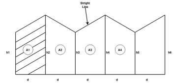
Area 

Total area =A = d (
2. Simpson's rule: -
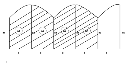


Total area=A=
We need odd number of offsets.
If even number of offsets.
One area is calculated by trapezoidal formula and added with remaining area, calculated by Simpson’s formula.


.
.
.
Total A =?
1.15.2 Volume
If parallel areas at equal interval are available (or can be found)
1.Trapezoidal formula

2.Simpson's Formula: -

- It is precise instrument for measuring angles in the horizontal and vertical planes.
- It is accurate method or instrument used for measuring horizontal and vertical angles.
- It can use in prolonging survey lines, and finding elevations etc.
- It is also used for levelling.
- The line of sight of instrument can be rotated 180 degree in vertical plane about its horizontal axis.
Following are part of theodolite
(1) Telescope
- Telescope in theodolite is used for focusing at which object piece and eye piece at other.
- It rotates about horizontal axis in vertical plane.
(2) Vertical circle
- It is fitted to telescope and more simultaneously.
- Graduation is there in each quadrant from 0 to 90 degree.
(3) Index frame
- It is also known as Vernier frame or t frame.
- It consists of two parts vertical and horizontal.
- Horizontal arm is used to measure Vertical angle.
- Vertical arm Culp’s to lock telescope at certain level.
(4) Standards
- They are the frames which support telescope and it is rotated about vertical axis.
- It is also called as A frame.
(5) Upper plate
- It gives support to standards.
- It consists of two Vernier with magnifiers which are arranged diagonally.
- Upper clamping screw with respect to tension screw which helps to fixing with the lower plate.
(6) Lower plate
- It contains scale on which 0 to 360 reading are graduate.
- It is also called as scale plate.
- It is attached to outer spindle.
- It consists lower clamping screw.
- If lower clamp is loosened and upper is tightened both plates can rotate together.
- if the procedure is reversed that is lower clamp is tightened and upper loosened and then upper plate is movable and lower plate is fixed.
7) Levelling head
- It contains two parallel triangular plates known as tri batch plates.
- Upper path that is upper tribrach used to level up per plates and telescope with help of levelling screw.
- Lower part i.e., lower tribrach plate and is attached through tripod.
8) Shifting head
- It contains two parallel plates which are right angle to each other with one of them is parallel to trunnion axis.
9) Tripod: -
- It is just stand for theodolite which mounted over it.
- Levelled position is required for tripod to give correct observations.
- Steel shoes are there at the end of tripod leg.
- These legs hold the ground strongly
10) Plumb Bob
- It is cone-shaped weight attached or tie with long thread.
- These is used for entering of theodolite.
11) Magnetic compass: -
- It is in circular compass box in centre of upper plate and used for selecting meridian.
a) Horizontal angle: -
- Horizontal angle are used to find bearing and direction in control survey.
- It is also used for locating detail when mapping.
b) Vertical angle: -
-It is used to find out the height of points and to calculate slope connections.
Measurement of horizontal angle
1) To measure angle of ABC, instrument is set to B.
2) Upper clamp is loosened and lower clamp is fixed.
3) Telescope is turned and Vernier A is a set O and Vernier B to 180°.
4) Now lower clamp is loosened and tightened scope is pointed to A and bisect ranging rod at A.
5) Now lower clamp is tightened and lower tangent screw is turned to perfectly bisect ranging rod at A.
6) Now upper clamp is loosened and telescope is turned clockwise to bisect the C which is tightened at upper clamp.
7) Now, Vernier reading A and B is noted.
8) Vernier A result in angle directly and Vernier B result reading by subtracting initial reading from final reading.
Measurement of vertical angle
1) The zeros of Vernier are set to 0 degree to vertical circle.
2) Telescope is den clamped.
3) Plate bubble are brought to center with foot screw and altitude bubble is brought to centre by clip screw.
4) Telescope in bisect to point A and measure the angle of elevation.
5) Finally reading of Vernier is noted and elevation angle is also noted.
6) Now, face of instrument is changed and point A is bisected again and reading are noted.
7) Telescope is lowered slowly and B is bisected to measure angle of depression.
Horizontal and vertical control are formed to create framework around other surveys can be adjusted.
Horizontal and vertical control surveys are used in accurate mapping projects in the construction of underground utility systems, and in roadways, power lines, tunnels.
Horizontal positioning | Vertical positioning |
a) Triangulation | a) Geodetic levelling |
b) Trilateration | b) Trigonometric heighting |
c) Traversing | c)Basometric levelling |
d) Astronomical positioning |
|
e) GPS |
|
It is a network of triangles used to find the distance and position of point.
Network is done by measuring length of one side of a triangle and reducing its angle and length of other two sides by observation from baseline.
- It is small device which is used to define location of triangulation station such that it is easily observed from other stations.
- Signal must be vertical over station.
- It is placed centrally over station mark.
- It is important to place over station mark because accuracy of triangulation system depends on signal that is entering of signal.
Signal: -
1) Opaque signal
2) Luminous signal
a) Opaque signal: -
Is type of signal used where less accuracy and for short sight distance (i.e., not more than 30 kilometer)
It must be used in day time only.
Cheaper than luminous signal.
Example of opaque signal
(i)Target signal – suitable for distance up to 30 km
(ii) Pole signal- distance up to 6 km
(iii) Elevated signal – elevated tower is used as signal and suitable for distance up to 30 to 40 km.
(iv)Stone signpost
(v)Pole and brush signal
b) Luminous signal: -
This type of signal basically used for geodetic survey because of quite distinct and have clear visibility even for long distance (more than 30 km).
It is used for day as well as night also.
Luminous signal
-Sun signal
-Light signal
(i) Sun signal - also known as heliotrope. Heliotrope reflects sun rays towards station.
(ii) Night signals - observation is at night. E.g., Drummond's light and magnesium lamp with parabolic reflector.
Choices of Site selection for baseline
Following factors must be accounted for while selecting the site for baseline
a. Ground should be firm and smooth
b. Two ends of baseline must be indivisible.
c. Site must be free from any obstruction throughout base length.
d. Site should be well shaped triangle can be obtained while connecting it’s and stations to main triangulation station.
e. Site should be such that less length of baseline as specified is available.
f. Site must be level.
g. High undulating ground should be avoided.
1) Tape
2) Straining device
3) Weight and pulley
4) Thermometer and finely divided scale.
5) Marking tripod or station rakes
6) Supporting tripods
7) Chains
Chain / Tape corrections
1)Correction due to standardization
Correction per chain length


Total correction

True length of line
Alternate solution of Q → (1)
Core (1) L = 30m and' = 30.40 m
1) C' = L'-L = 30.40-30 = (+) 0.40m
2) Number of chains = n = 
3) Total correction
 = 42.3×0.40= (+)169.20
4) Total length
l = 12690+169.20 = 16459.2 m
1) Correction due to slope
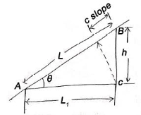
This correction is always a negative correction.
Correct distance between any two points on ground is horizontal distance.
Correction required = L – 

 approximate formula
If  angle is given

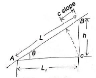

2) Correction due to wrong alignment

Same as slope correction
If endpoint of chain is not put on the straight line between points to be measured


Correction is always negative.
4)Temperature correction
If  is the temperature at the time of standardization.
 is the temperature at the time of measurement
L = length of chain / tape
 = Coefficient of thermal expansion

| Length of chain | Noted down value | Error | Correct |
| Increase | Less | Negative | Positive |
| Decrease | More | Positive | Negative |
5) Pull correction
 = value of pull applied at the time of standardization
 value of pull applied at measurement
L = length of chain / tape
 Cross sectionarea of tape
E = Young's modulus
Pull correction = 
| Error | Correction |
| Negative | Positive |
| Positive | Negative |
6) Sag correction
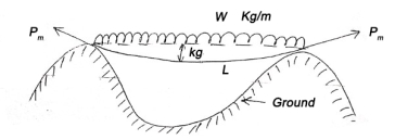

This collection is always negative.
Formal tension
The value of pull 
For which positive pull correction is exactly equal to negative sag correction is called normal tension.

It is also known as eccentric station.
Satellite station is a false station because it is not possible to set the instrument over the structure false station point is assumed.
It is also a place where movement of satellite is followed and receive information from them.
It is defined as the process of computing the correct angle from observed angle is called reduction to centre.
This method is often applied in triangulation when it is not possible to occupy a triangulation station.
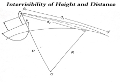
The maximum distance on ground that is visible to a person at certain height is called distance of visible horizon.
If there is no effect of refraction: -


 h=in meter, d=in km
Case (1) if horizontal distance up to the point can be mean.
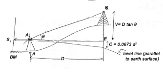
Given values: -
1) Distance 'D'
2) Angle=
3) Staff reading 
Vertical height
V = D tan
R.L. of B = RL of B.M. + 
C= combined correction due to Earth curvature/ refraction
= (+) 0.0673  [positive for RL]
Case (2) If distance D cannot be measured
Given (known) values: -
1) Distance 'B' = AB
2) Staff readings 
Difference of staff readings 
3) Angle measured
From 
From 
4) RL of BM
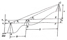

V+S=(B+D) tanθ1 (1)


RL of 
If height of target is not equal to the instrument axis, then measured angles are to be corrected by the axis single correction or eye object correction.
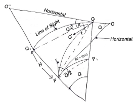
 = height of instrument at P for observation to Q.
 = height of instrument at Q forobservation to P.
 height of signal at P, instrument being at Q.
 =
= 
d = horizontal distance between P and Q
 = Observed of elevation and corrected for axis signal
 = Observed of depression and corrected for axis signal.
 = Angle of elevation corrected for axis signal.
 = — depression —
From observation from P to Q
tanδ1=(δ2-h1) Cos2α/D
δ1 is negative for angle of elevation.
Now, corrected angle of elevation 
α1=α-δ1
 is very small.


For observation from Q to P

 is positive for angle of depression
Now, corrected angle of depression

If  is very small.


References:
1 Madhu, N, Sathikumar, R and Satheesh Gobi, Advanced Surveying: Total Station, GIS and Remote
Sensing, Pearson India, 2006.
2 Manoj, K. Arora and Badjatia, Geomatics Engineering, Nem Chand & Bros, 2011
3 Bhavikatti, S.S., Surveying and Levelling, Vol. I and II, I.K. International, 2010 4 Chandra, A.M., Higher
Surveying, Third Edition, New Age International (P) Limited, 2002.
5 Anji Reddy, M., Remote sensing and Geographical information system, B.S.
6 Arora, K.R., Surveying, Vol-I, II and III, Standard Book House, 2015.


