Unit-1
Introduction-Branches of geology useful to civil engineering
Geology provides a systematic knowledge of construction materials andtheir occurrence, formation, durability, strength, hardness, and uses. Beforestarting any major/minor civil construction at a place, a detailed geological report which is accompanied by geological maps and sections is prepared. The detailed geological report contains types of rocks (Petrology), types of formations (geological structures), and physical properties of the earth(Geophysics). Petrology is the study of rocks, where it provides rock hardness, chemical composition, strength, durability, etc. Petrology is particularly important as it gives therequired load-bearing properties of the rock which will help in deciding the usage. Sometimes there is a possibility of rocks of acceptable compressive strength being susceptible to chemical reactions, and may not be preferred for construction in certain fields.
Structural Geology is the study of patterns that are formed below the earth like folds, faults, joints, and unconformity. Structural Geology is the necessary factor at present for major construction projects. On account of the effects of these anomalies on the structures, there are few examples with negligible geological considerations which create loss to both life and property. In recent years it has been noticed that more importance is given to the study of geological structures due to past experiences. Geophysics is the study of the physical properties and composition of the interior earth using a gravity field, magnetic field, and geothermal field. Modern geophysics methods that are used in civilengineering are mainly non-destructive testing. Equipment like geophones is employed to map the interiors of the earth's crust by creating vibrations at a certain point and recording the same at a particular distance. Geophones use the concept of wave propagation to map the materials that may be present in the field.Geophysics is particularly important for shallow constructions where theunderground amenities are not known.
The importance of geology in civil engineering may be briefly outlined as follows:
It is defined as that of applied science which deals with the application of geology for a safe, stable, and economic design and construction of a civil engineering project.
Engineering geology is almost universally considered as essential as that of soil mechanics, the strength of the material, or the theory of structures.
The application of geological knowledge in planning, designing, and construction of big civil engineering projects.
The basic objects of a course in engineering geology are two folds.
It enables a civil engineer to understand the engineering implications of certain condition should relate to the area of construction which is essentially geological.
It enables a geologist to understand the nature of the geological information that is essential for a safe design and construction of civil engineering projects.
The scope of geology can be studied regarding major activities of the profession of a civil engineer which are Construction, Water resources development, and Town and regional planning
Topographic Maps: It gives details of relief features and understands the relative merits and demerits of all the possible sides of a proposed structure.
Hydrological maps:This map gives broad details about the distribution and geometry of the surface of the water channel.
Geological maps: The petrological characters and structural disposition of rock types gives an idea about the availability of construction materials.
Geological Survey of India (GSI) Established in 1851, started its voyage to investigate for and assess coal and other mineral resources of the country with regional level exploration. In the 160 years since its foundation, GSI has continued to grow and diversify into various geoscientific activities and delivered impeccable contributions in the arena of geosciences. After independence, GSI‟s activities in mineral exploration, as well as baseline surveys, have increased manifold to sustain the momentum of national economic development and to meet the increasing demands of various stakeholders. Over the years, it has not only developed into a huge repository of precious geoscientific data applied in various developmental sectors in the country but has also attained the status of a geo-scientific organization of international repute. The principal function of GSI relates to the creation and updation of national geoscientific data and mineral resource assessment, air-borne and marine surveys, and conducting multifarious geotechnical, geo-environmental, and natural hazards studies, glaciology, seismotectonic, etc. and to nurture studies on fundamental research. In all the developmental facets of the country including coal, steel, cement, metals/ minerals, and power industries, GSI made a neat contribution and remained relevant in the national context. The outcome of the work of GSI has immense societal value as well as relevance to global perspective adopting state-of-the-art technologies and using cutting-edge methodologies. Functioning and annual programs of GSI assume significance in the national perspective since it is directly related to delivering the public good. With its headquarters in Kolkata, GSI has six Regional offices at Lucknow, Jaipur, Nagpur, Hyderabad, Shillong, and Kolkata and offices in almost all states of the country. The Geological Survey of India is an attached office to the Ministry of Mines. The Union Cabinet constituted a High Powered Committee (HPC) to thoroughly review the functioning of the Geological Survey of India and assess its capacity to meet the emerging challenges taking into account the technological and manpower resources of the organization. The report of the Committee was submitted in March 2009 and approved by the Union Cabinet in October 2011. The revised organizational structure as proposed by HPC has largely been implemented. Activity Domain of GSI The GSI is the prime provider of basic earth science data to the government, industry, and the public, as well as a responsive participant in international geoscientific fora. The vibrant steel, coal, metals, cement, and power industries, which expanded phenomenally in the postindependence era, bear eloquent testimony to the GSI‟s relevance in the national context. The geoscientific work of GSI encompasses practically the entire gamut of earth sciences and thus great responsibilities are bestowed on the organization. Earth science by its very nature is highly multidisciplinary and has immense societal values. To remain relevant for the cause of the society, mankind, global perspective, and its environment, GSI faced challenges of the time to reorient its organizational structure and strengthen its capacity building. Following the HPC recommendations, GSI is executing its programs through Mission-Region hybrid matrix mode with its five Mission offices and three Support Systems. Activities of GSI function around Five Missions / Seven Schemes and three Support Systems (Table 1.1).


Table 1.1
The National Institute of Rock Mechanics (NIRM) is a premierecenter for research in applied and basic rock mechanics. It is an ISO 9001: 2000 certified research Institute. The Institute provides research and consultancy services for improving safety and productivity in the mining and civil engineering sectors. With its rich experience, underpinned by the strength of world-class software and laboratory facilities, NIRM plays a vital role in offering technical services in mining, hydroelectric, and tunneling projects, site evaluation for construction of nuclear power plants, and other infrastructure development projects both in India and abroad. Due to its assured quality of work, the Institute has been receiving several challenging projects from governmental and non-governmental organizations.
NIRM has been carrying out research work through both government-funded and industry-sponsored S&T and consultancy projects. The Institute has been extending its support to the industry in the following areas :
The major projects undertaken by NIRM, to mention a few, are the underground cavern for storage of crude oil at Vishakhapatnam, controlled blasting for Bangalore metro project, site evaluation for a nuclear power plant at Kudankulam, construction-stage technical services for a nuclear plant at Rawatbhatta, Rajasthan, DPR stage investigation at Bunakha project, Bhutan, achieving yet another milestone in the annals of NIRM during the year 2010-11.
During the year 2010-11, 37 projects were completed and 33 were in progress. The finance of the Institute remained satisfactory during the year, by realizing a total cash flow of 8.6 crores. A highly skilled and creative research team of NIRM has contributed 51 technical papers at various national/international journals and proceedings of seminars.
Minerals
Mineral,naturally occurring homogeneous solid with definite chemical composition and a highly ordered atomic arrangement; it is usually formed by inorganic processes. There are several thousand known mineral species, about 100 of which constitute the major mineral components of rocks; these are the so-called rock-forming minerals.
A mineral, which by definition must be formed through natural processes, is distinct from the synthetic equivalents produced in the laboratory. Artificial versions of minerals, including emeralds, sapphires, diamonds, and other valuable gemstones, are regularly produced in industrial and research facilities and are often nearly identical to their natural counterparts.
By its definition as a homogeneous solid, a mineral is composed of a single solid substance of uniform composition that cannot be physically separated into simpler chemical compounds. Homogeneity is determined relative to the scale on which it is defined. A specimen that appears homogeneous to the unaided eye, for example, may reveal several mineral components under a microscope or upon exposure to X-ray diffraction techniques. Most rocks are composed of several different minerals; e.g., granite consists of feldspar, quartz, mica, and amphibole. Also, gases and liquids are excluded by a strict interpretation of the above definition of a mineral. Ice, the solid-state of water (H2O), is considered a mineral, but liquid water is not; liquid mercury, though sometimes found in mercury ore deposits, is not classified as a mineral either. Such substances that resemble minerals in chemistry and occurrence are dubbed mineraloids and are included in the general domain of mineralogy.
Composition
Since a mineral has a definite composition, it can be expressed by a specific chemical formula. Quartz (silicon dioxide), for instance, is rendered as SiO2, because the elements silicon (Si) and oxygen (O) are its only constituents and they invariably appear in a 1:2 ratio. The chemical makeup of most minerals is not as well defined as that of quartz, which is a pure substance. Siderite, for example, does not always occur as pure iron carbonate (FeCO3); magnesium (Mg), manganese (Mn), and, to a limited extent, calcium (Ca) may sometimes substitute for the iron. Since the amount of the replacement may vary, the composition of siderite is not fixed and ranges between certain limits, although the ratio of the metal cation to the anionic group remains fixed at 1:1. Its chemical makeup may be expressed by the general formula (Fe, Mn, Mg, Ca)CO3, which reflects the variability of the metal content.
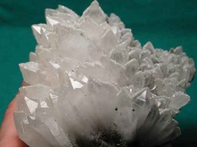
Fig. 1.1 Trigonal (rhombohedral) crystals of quartz.
Minerals display a highly ordered internal atomic structure that has a regular geometric form. Because of this feature, minerals are classified as crystalline solids. Under favorable conditions, crystalline materials may express their ordered internal framework by a well-developed external form, often referred to as crystal form or morphology. Solids that exhibit no such ordered internal arrangement are termed amorphous. Many amorphous natural solids, such as glass, are categorized as mineraloids.
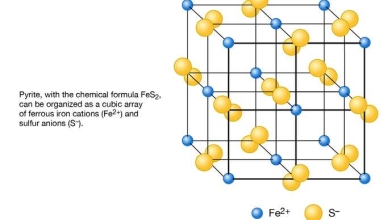
Fig 1.2 Schematic representation of the structure of pyrite (FeS2) as based on a cubic array of ferrous iron cations (Fe2+) and sulfur anions (S−).
Traditionally, minerals have been described as resulting exclusively from inorganic processes; however, current mineralogic practice often includes as minerals those compounds that are organically produced but satisfy all other mineral requirements. Aragonite (CaCO3) is an example of an inorganically formed mineral that also has an organically produced, yet otherwise identical, counterpart; the shell (and the pearl, if it is present) of an oyster is composed to a large extent of organically formed aragonite. Minerals also are produced by the human body: hydroxylapatite [Ca5(PO4)3(OH)] is the chief component of bones and teeth, and calculi are concretions of mineral substances found in the urinary system.
Mineralogists are scientists who study minerals. One of the things mineralogists must do is identify and categorize minerals. While a mineralogist might use a high-powered microscope to identify some minerals, most are recognizable using physical properties.
Color, Streak, and Luster
Diamonds are popular gemstones because the way they reflect light makes them very sparkly. Turquoise is prized for its striking greenish-blue color. Notice that specific terms are being used to describe the appearance of minerals.
1.Color
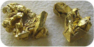
Fig. 1.3
This mineral is shiny, very soft, heavy, and gold in color, and is gold.
Color is often useful, but should not be relied upon. Different minerals may be the same color. Real gold, as seen in figure 1.3, is very similar in color to the pyrite.
Additionally, Some minerals come in many different colors. Quartz, for example, maybe clear, white, gray, brown, yellow, pink, red, or orange. So color can help but do not rely on color as the determining property. Fig. 1.4 shows one sample of quartz that is colorless and another purple quartz. A tiny amount of iron makes the quartz purple. Many minerals are colored by chemical impurities.
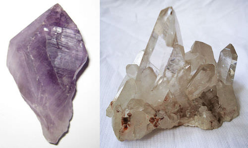
Fig. 1.4 Purple quartz, known as amethyst, and clear quartz are the same mineral despite the different colors.
2. Luster
Luster describes the reflection of light off a mineral’s surface. Mineralogists have special terms to describe luster. One simple way to classify luster is based on whether the mineral is metallic or non-metallic. Minerals that are opaque and shiny, such as pyrite, have a metallic luster. Minerals such as quartz have a non-metallic luster.
Luster is how the surface of a mineral reflects light. It is not the same thing as color, so it crucial to distinguish luster from color. For example, a mineral described as “shiny yellow” is being described in terms of luster (“shiny”) and color (“yellow”), which are two different physical properties. Standard names for luster include metallic, glassy, pearly, silky, greasy, and dull. It is often useful to first determine if a mineral has a metallic luster. A metallic luster means shiny like polished metal. For example cleaned polished pieces of chrome, steel, titanium, copper, and brass all exhibit metallic luster as do many other minerals. Of the nonmetalliclusters, glassy is the most common and means the surface of the mineral reflects light like glass. Pearly luster is important in identifying the feldspars, which are the most common type of mineral. Pearly luster refers to a subtle iridescence or color play in the reflected light, the same way pearls reflect light. Silky means reflecting light with a silk-like sheen. Greasy luster looks similar to the luster of solidified bacon grease. Minerals with dull luster reflect very little light. Identifying luster takes a little practice. Remember to distinguish luster from color.
Different types of non-metallic luster are described in table1.2.
Table 1.2. Six types of non-metallic luster.

Fig 1.5. (a) Diamond has an adamantine luster. (b) Quartz is not sparkly and has a vitreous, or glassy, luster. (c) Sulfur reflects less light than quartz, so it has a resinous luster.
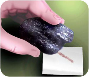
Fig 1.6. The streak of hematite across an unglazed porcelain plate is red-brown.
Streak is the color of a mineral’s powder. Streak is a more reliable property than color because streak does not vary. Minerals that are the same color may have a different colored streak. Many minerals, such as the quartz in fig 1.4, do not have a streak.To check streak, scrape the mineral across an unglazed porcelain plate (Fig 1.6). Yellow-gold pyrite has a blackish streak, another indicator that pyrite is not gold, which has a golden yellow streak.
4.Specific Gravity
Density describes how much matter is in a certain amount of space: density = mass/volume.
Mass is a measure of the amount of matter in an object. The amount of space an object takes up is described by its volume. The density of an object depends on its mass and its volume. For example, the water in a drinking glass has the same density as the water in the same volume of a swimming pool.
The specific gravity of a substance compares its density to that of water. More dense substances have higher specific gravity.
5.Hardness
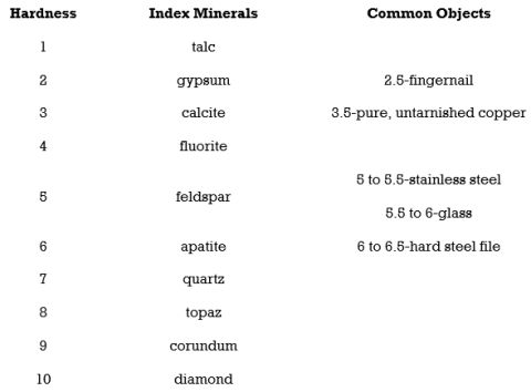
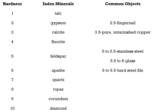
Hardness is the strength with which a mineral resists its surface being scraped or punctured. In working with hand samples without specialized tools, mineral hardness is specified by the Mohs hardness scale. The Mohs hardness scale is based on 10 reference minerals, from talc the softest (Mohs hardness of 1), to diamond the hardest (Mohs hardness of 10). It is a relative, or nonlinear, scale. A hardness of 2.5 simply means that the mineral is harder than gypsum (Mohs hardness of 2) and softer than calcite (Mohs hardness of 3). To compare the
hardness of two minerals see which mineral scratches the surface of the other.
With a Mohrs scale, anyone can test an unknown mineral for its hardness. Imagine you have an unknown mineral. You find that it can scratch fluorite or even feldspar, but apatite scratches it. You know then that the mineral’s hardness is between 5 and 6. Note that no other mineral can scratch a diamond.
6. Cleavage and Fracture
Breaking a mineral breaks its chemical bonds. Since some bonds are weaker than other bonds, each type of mineral is likely to break where the bonds between the atoms are weaker. For that reason, minerals break apart in characteristic ways.
7. Cleavage
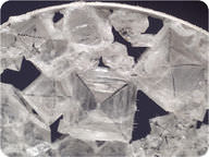
Fig 1.7 A close-up view of sodium chloride in a water bubble aboard the International Space Station.
Cleavage is the tendency of a mineral to break along certain planes to make smooth surfaces. Halite breaks between layers of sodium and chlorine to form cubes with smooth surfaces (fig 1.7).
A mineral that naturally breaks into perfectly flat surfaces is exhibiting cleavage. Not all minerals have cleavage. A cleavage represents a direction of weakness in the crystal lattice. Cleavage surfaces can be distinguished by how they consistently reflect light as if polished, smooth, and even. The cleavage properties of a mineral are described in terms of the number of cleavages and, if more than one cleavage, the angles between the cleavages. The number of cleavages is the number of directions in which the mineral cleaves. A mineral may exhibit 100 cleavage surfaces parallel to each other. Those represent a single cleavage because the surfaces are all oriented in the same direction. The possible number of cleavages a mineral may have are 1,2,3,4, or 6. If more than 1 cleavage is present, and a device for measuring angles is not available, simply state whether the cleavages intersect at 90° or not 90°.
To see mineral cleavage, hold the mineral up beneath a strong light and move it around, move it around some more, to see how the different sides reflect light. A cleavage direction will show up as a smooth, shiny, evenly bright sheen of light reflected by one set of parallel surfaces on the mineral.
Mica has cleavage in one direction and forms sheets (Fig 1.8).
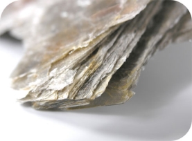
Fig. 1.8 Sheets of mica.
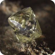
Fig 1.9 This rough diamond shows its octahedral cleavage.
Minerals can cleave into polygons. Fluorite forms octahedrons (Fig 1.9).
One reason gemstones are beautiful is that the cleavage planes make an attractive crystal shape with smooth faces.
8. Fracture
A fracture is a break in a mineral that is not along a cleavage plane. Fracture is not always the same in the same mineral because the fracture is not determined by the structure of the mineral.
Minerals may have characteristic fractures (Fig 1.10). Metals usually fracture into jagged edges. If a mineral splinters like wood, it may be fibrous. Some minerals, such as quartz, form smooth curved surfaces when they fracture.

Fig 1.10 Chrysotile has a splintery fracture.
All minerals have a fracture. Fracture is breakage, which occurs in directions that are not cleavage directions. Some minerals, such as quartz, have no cleavage whatsoever. When a mineral with no cleavage is broken apart by a hammer, it fractures in all directions. Quartz is said to exhibit conchoidal fracture. Conchoidal fracture is the way a thick piece of glass breaks with concentric, curving ridges on the broken surfaces. However, some quartz crystals have so many flaws that instead of exhibiting conchoidal fracture they simply exhibit irregular fracture. Irregular fracture is a standard term for fractures that do not exhibit any of the qualities of the other fracture types. In introductory geology, the key fracture types to remember are irregular, which most minerals exhibit, and conchoidal, seen in quartz.
9. Crystal Shape
All minerals are crystalline, but only some have the opportunity to exhibit the shapes of their crystals, their crystal forms. Many minerals in an introductory geology lab do not exhibit their crystal form. If a mineral has space while it grows, it may form natural crystals, with a crystal shape reflecting the geometry of the mineral’s internal crystal lattice. The shape of a crystal follows the symmetry of its crystal lattice. Quartz, for instance, forms six-sided crystals, showing the hexagonal symmetry of its crystal lattice.
There are two complicating factors to remember here:
The description of the type and degree of alteration of coarse mineral grains, and the nature of their alteration products, is important for the interpretation of the coarse fraction of the groundmass. The term alteration is used here in a wide sense, covering changes caused both by geological processes (e.g., burial diagenesis, deuteric reactions, hydrothermal activity) and by pedogenic processes. The latter type of alteration, resulting from interaction with atmospheric agents and organisms in earth-surface conditions, is generally called weathering. It is evident but sometimes overlooked by micromorphologists, that changes requiring high temperatures or pressures cannot take place in soils and therefore cannot be interpreted as pedogenic.
Susceptibility to alteration is a reflection of mineral stability in soil environments, which is determined by many factors, including temperature, moisture conditions, pH, redox conditions, degree of leaching, and the nature, composition, and grain size of the mineral.For intrinsic mineral stability, a sequence was already proposed by Goldich (1938), limited to minerals that are common in magmatic rocks. He proposed two parallel series, one from olivine over augite and hornblende to biotite, and the other from Ca-rich to Na-rich plagioclase, both continued by a series from potassium feldspar over muscovite to quartz. Related efforts for mineral stability classification are various weathering indexes, based on chemical composition and crystal structure. These approaches are not always applicable because other factors may interfere. For instance, augite may be less stable than associated olivine in basalt because of its prominent cleavage. Classifications of mineral stability that have been proposed in sedimentology are also not entirely suitable in pedology because they take physical stability during transport into account, which is not relevant for soil environments.
Alteration of mineral grains can occur in the form of transformation to newly formed mineral phases, but it can also consist of congruent dissolution, without in situ formations of alteration products. In this case, with calcite and quartz dissolution as common examples, circum-granular voids (also called contact voids) are formed, separating the affected grain from surrounding or neighboring components. This space can later be filled with other minerals, giving the false impression of mineral transformation or coupled dissolution-precipitation. In these and other contexts, the formation of an enclosing mineral phase can contribute to the dissolution of the surrounded grain through the effect of crystallization pressure on solubility. After complete dissolution of a mineral grain, a mouldic void, preserving the original shape of the grain, can be left, if the surrounding material is sufficiently coherent. This has mostly been documented for minerals such as gypsum or calcite, but under tropical conditions, it can also occur for less soluble minerals such as quartz. After their development, mouldic voids can be filled with authigenic minerals, resulting in the development of pseudomorphs after the dissolved phase. The same result can be reached by gradual dissolution and mineral formation, which often requires an input of elements from external sources. Examples include goethite pseudomorphs after garnet, requiring Fe input, and gibbsite pseudomorphs after feldspar, requiring Al input.
In the case of alteration through mineral transformation, a certain crystallographic relationship can exist between the original phase and its transformation product. When a mineral is completely replaced by newly formed material, by dissolution-precipitation or transformation, an ‘alteromorph’ is formed, preserving the original boundaries of the weathered mineral. Alteration is described as isomorphous when the alteromorph has the same shape and size as the original mineral grain, mesomorphous when the shape has been preserved but the size has changed in one or two directions, and katamorphous when the shape has been completely lost.
Polyphase or polygenic alteration is a common phenomenon. The original mineral is in that case altered to another product, which is, in turn, transformed to another phase. For instance, hornblende in igneous rocks can be altered to biotite by late-magmatic alteration, followed by biotite transformation to vermiculite and next to kaolinite in soil conditions, resulting in kaolinite alteromorphs after hornblende. If the first step of non-pedogenic alteration is not complete, two associated inherited mineral phases remain side by side, which may alter subsequently following different pathways, making interpretation quite difficult. Such complex situations can only be studied using microscopic techniques. During pedoplasmation, most unstable alteromorphs are destroyed.
Pellicular and irregular linear weathering patterns are commonly observed for minerals without well-expressed cleavage or fracture patterns (e.g., garnet, olivine), whereas parallel and cross-linear patterns point to minerals with prominent clear cleavage (e.g., pyroxenes, amphiboles, micas).
Besides chemical weathering, also physical weathering is visible in thin sections. The most important processes are fracturing by the growth of ice or pedogenic minerals in cracks. The latter include salt weathering, which is mainly observed for arid environments, but similar processes can take place in tropical soils, for instance through gibbsite formation. Because the mineralogical and chemical composition of the grains does not change, this process cannot be detected by various methods, except thin section studies and grain-size analyses.
Optical mineralogy involves studying rocks and minerals by studying their optical properties. Some of these properties are macroscopic and we can see them in mineral hand specimens. But generally, we use a petrographic microscope, also called a polarizing microscope (Figures 5.1 and 5.2 show examples), and the technique is called transmitted light microscopy or polarized light microscopy (PLM). A fundamental principle of PLM is that most minerals – even dark-colored minerals and others that appear opaque in hand specimens – transmit light if they are thin enough. In standard petrographic microscopes, polarized light from a source beneath the microscope stage passes through samples on the stage and then to your eye(s).
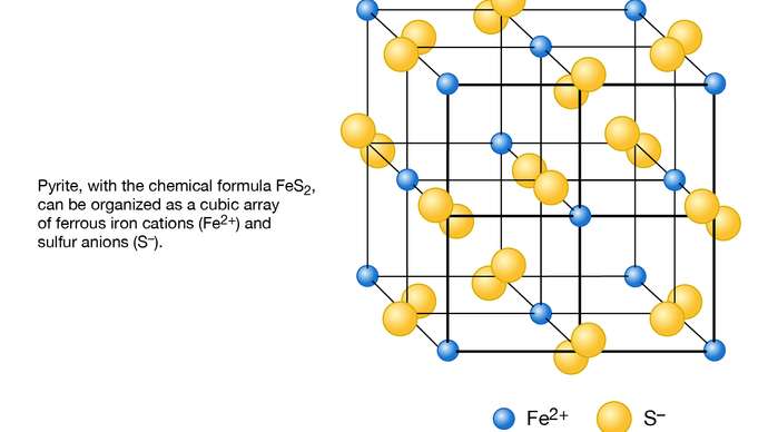
Fig 1.11 Close-up view of microscope lenses and a thin section
One approach to PLM involves examining grain mounts, which are ground-up mineral crystals on a glass slide. The grains must be thin enough so that light can pass through them without a significant loss of intensity, usually 0.10 to 0.15 mm thick. We surround a small number of grains with a liquid called refractive index oil, and then place a thin piece of glass, called a coverslip, over the grains and liquid. The photo in Figure 1.12, below, shows garnet grains in a grain mount.
Grain mounts and refractive index oils are necessary for making some types of measurements but are not the focus of this chapter. They were extensively used in the past, but are not much used today. For more detailed information about studying minerals in grain mounts consult an optical mineralogy textbook.
Most optical mineralogy today involves specially prepared thin sections (0.03-mm-thick specimens of minerals or rocks mounted on glass slides).Figure 1.13 above shows a microscope view of a thin section that contains several minerals (biotite, hornblende, and magnetite are labeled, and the clear grains around them are mostly quartz and plagioclase). Whether looking at grain mounts or thin sections, transmitted light microscopy allows us to determine and measure properties that are otherwise not discernible. We can identify minerals, sometimes their compositions, and we can observe mineral relationships that allow us to learn about mineral origins.
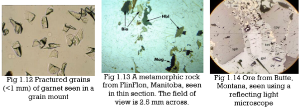
Minerals with metallic luster and a few others are termed opaque minerals. They will not transmit light even if they are thin-section thickness. So they always appear black when viewed with a microscope. Magnetite is an opaque mineral; the photo in Figure 1.13 contains several small black magnetite grains. For studying opaque minerals, transmitted light microscopy is of little use. Reflected light microscopy (RLM), a related technique, can reveal some of the same properties. As the name implies, when using RLM, the light source is above the sample and light reflects from the sample to our eye. RLM, although an important technique for economic geologists who deal with metallic ores, is not used by most mineralogists or petrologists. So we discuss it only briefly in this book. Figure 1.14 shows a view of ore from Butte, Montana, seen with a reflecting light microscope. It contains several opaque minerals: galena, sphalerite, pyrite, and chalcopyrite. They appear in various shades of black, gray, and light yellow.
Most minerals can be identified when examined with a petrographic microscope, even if unidentifiable in hand specimens. Optical properties also allow a mineralogist to estimate the composition of some minerals. For example, we can learn the magnesium-to-iron ratio of olivine, (Mg,Fe)2SiO4, based on optical properties. And we can also determine the albite and anorthite content of plagioclase feldspar.
Table 1.4 summarizes the optical properties used for mineral identification and gives the properties of some common minerals. At the largest level, we divide minerals into opaque minerals and nonopaque minerals. Opaque minerals will not transmit light unless the mineral grains are much thinner than normal thin sections. We further divide nonopaque minerals into those that are isotropic (having the same properties in all directions) and those that are anisotropic (having different optical properties in different directions). Finally, we divide the anisotropic minerals into those that are uniaxial and those that are biaxial, and according to whether they have a positive or negative optic sign. We discuss the details of these and other diagnostic properties below.
Besides mineral identification, the polarizing microscope reveals important information about rock-forming processes (petrogenesis). When we examine thin sections, distinguishing igneous, sedimentary, and metamorphic rocks is often easier than when we look at hand specimens. More significantly, we can identify minerals and distinguish among different types of igneous, sedimentary, and metamorphic rocks. The microscope allows us to see textural relationships in a specimen that give clues about when and how different minerals in an igneous rock formed. Microscopic relationships between mineral grains allow us to determine the order in which minerals crystallized from magma, and we can identify minerals produced by alteration or weathering long after the crystals first formed. Similar observations are possible for sedimentary or metamorphic rocks. Only the microscope can give us such information, information that is essential if rocks are to be used to interpret geological processes and environments.
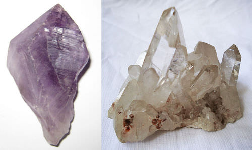
Table 1.4
Mineral characterization involves the study of minerals in terms of their size, habit, chemical composition, morphology, textural position, association, and other attributes.
X-ray diffraction analysis (XRD), image analysis, quantitative electron probe microanalysis (EPMA), and scanning electron microscopy (SEM) are becoming routine methods and supplement traditional microscopic studies and geochemical analysis.

Fig. 1.15
A typical SEM instrument, showing the electron column, sample chamber, EDS detector, electronics console, and visual display monitors.
The scanning electron microscope (SEM) uses a focused beam of high-energy electrons to generate a variety of signals at the surface of solid specimens. The signals that derive from electron-sample interactions reveal information about the sample including external morphology (texture), chemical composition, and crystalline structure, and orientation of materials making up the sample. In most applications, data are collected over a selected area of the surface of the sample, and a 2-dimensional image is generated that displays spatial variations in these properties. Areas ranging from approximately 1 cm to 5 microns in width can be imaged in a scanning mode using conventional SEM techniques (magnification ranging from 20X to approximately 30,000X, a spatial resolution of 50 to 100 nm). The SEM is also capable of performing analyses of selected point locations on the sample; this approach is especially useful in qualitatively or semi-quantitatively determining chemical compositions (using EDS), crystalline structure, and crystal orientations (using EBSD). The design and function of the SEM are very similar to the EPMA and considerable overlap in capabilities exists between the two instruments.
Fundamental Principles of Scanning Electron Microscopy (SEM)
Accelerated electrons in an SEM carry significant amounts of kinetic energy, and this energy is dissipated as a variety of signals produced by electron-sample interactions when the incident electrons are decelerated in the solid sample. These signals include secondary electrons (that produce SEM images), backscattered electrons (BSE), diffracted backscattered electrons (EBSD that are used to determine crystal structures and orientations of minerals), photons (characteristic X-rays that are used for elemental analysis and continuum X-rays), visible light (cathodoluminescence--CL), and heat. Secondary electrons and backscattered electrons are commonly used for imaging samples: secondary electrons are most valuable for showing morphology and topography on samples and backscattered electrons are most valuable for illustrating contrasts in composition in multiphase samples (i.e. for rapid phase discrimination). X-ray generation is produced by inelastic collisions of the incident electrons with electrons in discrete orbitals (shells) of atoms in the sample. As the excited electrons return to lower energy states, they yield X-rays that are of a fixed wavelength (that is related to the difference in energy levels of electrons in different shells for a given element). Thus, characteristic X-rays are produced for each element in a mineral that is "excited" by the electron beam. SEM analysis is considered to be "non-destructive"; that is, x-rays generated by electron interactions do not lead to volume loss of the sample, so it is possible to analyze the same materials repeatedly.
Scanning Electron Microscopy (SEM) Instrumentation - How Does It Work?
Essential components of all SEMs include the following:
SEMs always have at least one detector (usually a secondary electron detector), and most have additional detectors. The specific capabilities of a particular instrument are critically dependent on which detectors it accommodates.
Applications
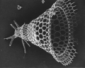
Fig 1.16
The SEM is routinely used to generate high-resolution images of shapes of objects (SEI) and to show spatial variations in chemical compositions:
1) Acquiring elemental maps or spot chemical analyses using EDS,
2) Discrimination of phases based on mean atomic number (commonly related to relative density) using BSE, and
3) Compositional maps based on differences in trace element "activators" (typically transition metal and Rare Earth elements) using CL.
The SEM is also widely used to identify phases based on qualitative chemical analysis and/or crystalline structure. Precise measurement of very small features and objects down to 50 nm in size is also accomplished using the SEM. Backscattered electron images (BSE) can be used for rapid discrimination of phases in multiphase samples. SEMs equipped with diffracted backscattered electron detectors (EBSD) can be used to examine microfabric and crystallographic orientation in many materials.
Strengths and Limitations of Scanning Electron Microscopy (SEM)
Strengths
There is arguably no other instrument with the breadth of applications in the study of solid materials that compare with the SEM. The SEM is critical in all fields that require the characterization of solid materials. While this contribution is most concerned with geological applications, it is important to note that these applications are a very small subset of the scientific and industrial applications that exist for this instrumentation. Most SEM's are comparatively easy to operate, with user-friendly "intuitive" interfaces. Many applications require minimal sample preparation. For many applications, data acquisition is rapid (less than 5 minutes/image for SEI, BSE, spot EDS analyses.) Modern SEMs generate data in digital formats, which are highly portable.
Limitations
Samples must be solid and they must fit into the microscope chamber. Maximum size in horizontal dimensions is usually on the order of 10 cm, vertical dimensions are generally much more limited and rarely exceed 40 mm. For most instruments, samples must be stable in a vacuum on the order of 10-5 - 10-6 torr. Samples likely to outgas at low pressures (rocks saturated with hydrocarbons, "wet" samples such as coal, organic materials, or swelling clays, and samples likely to decrepitate at low pressure) are unsuitable for examination in conventional SEM's. However, "low vacuum" and "environmental" SEMs also exist, and many of these types of samples can be successfully examined in these specialized instruments. EDS detectors on SEM's cannot detect very light elements (H, He, and Li), and many instruments cannot detect elements with atomic numbers less than 11 (Na). Most SEMs use a solid-state x-ray detector (EDS), and while these detectors are very fast and easy to utilize, they have relatively poor energy resolution and sensitivity to elements present in low abundances when compared to wavelength dispersive x-ray detectors (WDS) on most electron probe microanalyzers (EPMA). An electrically conductive coating must be applied to electrically insulating samples for study in conventional SEM's unless the instrument is capable of operation in a low vacuum mode.
Rocks, sediments, and precipitates are examples of geologic materials that are composed of minerals. Numerous analytical techniques are used to characterize these materials. One of these methods, X-ray powder diffraction (XRD), is an instrumental technique that is used to identify minerals, as well as other crystalline materials. In many geologic investigations, XRD complements other mineralogical methods, including optical light microscopy, electron microprobe microscopy, and scanning electron microscopy. XRD provides the researcher with a fast and reliable tool for routine mineral identification. XRD is particularly useful for identifying fine-grained minerals and mixtures or intergrowths of minerals, which may not lend themselves to an analysis by other techniques. XRD can provide additional information beyond basic identification. If the sample is a mixture, XRD data can be analyzed to determine the proportion of the different minerals present. Other information obtained can include the degree of crystallinity of the mineral(s) present, possible deviations of the minerals from their ideal compositions (presence of element substitutions and solid solutions), the structural state of the minerals (which can be used to deduce temperatures and (or) pressures of formation), and the degree of hydration for minerals that contain water in their structure. Some mineralogical samples analyzed by XRD are too fine-grained to be identified by optical light microscopy. XRD does not, however, provide the quantitative compositional data obtained by the electron microprobe or the textural and qualitative compositional data obtained by the scanning electron microscope.
Theory and Methodology
The three-dimensional structure of nonamorphous materials, such as minerals, is defined by regular, repeating planes of atoms that form a crystal lattice. When a focused X-ray beam interacts with these planes of atoms, part of the beam is transmitted, a part is absorbed by the sample, a part is refracted and scattered, and part is diffracted. Diffraction of an X-ray beam by a crystalline solid is analogous to diffraction of light by droplets of water, producing the familiar rainbow. X-rays are diffracted by each mineral differently, depending on what atoms make up the crystal lattice and how these atoms are arranged.
In X-ray powder diffractometry, X-rays are generated within a sealed tube that is under vacuum. A current is applied that heats a filament within the tube; the higher the current the greater the number of electrons emitted from the filament. This generation of electrons is analogous to the production of electrons in a television picture tube. A high voltage, typically 15-60 kilovolts, is applied within the tube. This high voltage accelerates the electrons, which then hit a target, commonly made of copper. When these electrons hit the target, X-rays are produced. The wavelength of these X-rays is characteristic of that target. These X-rays are collimated and directed onto the sample, which has been ground to a fine powder (typically to produce particle sizes of less than 10 microns). A detector detects the X-ray signal; the signal is then processed either by a microprocessor or electronically, converting the signal to a count rate. Changing the angle between the X-ray source, the sample, and the detector at a controlled rate between preset limits is an X-ray scan (figs. 1.17 and 1.18).
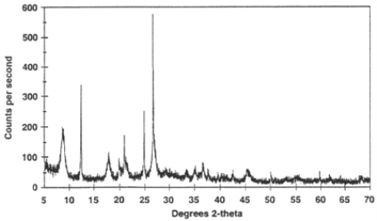
Figure 1.18 Example of an X-ray powder diffractogram produced during an X-ray scan.
When an X-ray beam hits a sample and is diffracted, we can measure the distances between the planes of the atoms that constitute the sample by applying Bragg's Law. Bragg's Law is:

where the integer n is the order of the diffracted beam,  is the wavelength of the incident X-ray beam, d is the distance between adjacent planes of atoms (the d-spacings), and
  is the angle of incidence of the X-ray beam. Since we know
  and we can measure
  , we can calculate the d-spacings. The geometry of an XRD unit is designed to accommodate this measurement (fig. 1.17). The characteristic set of d-spacings generated in a typical X-ray scan provides a unique "fingerprint" of the mineral or minerals present in the sample. When properly interpreted, by comparison with standard reference patterns and measurements, this "fingerprint" allows for the identification of the material.
Applications
XRD has a wide range of applications in geology, material science, environmental science, chemistry, forensic science, and the pharmaceutical industry, among others. At the U.S. Geological Survey, researchers use XRD to characterize geologic materials from a wide variety of settings; below are just a few examples.
Mineral-Environmental Studies
In studies of areas affected by acid mine drainage, the identification of secondary minerals and fine-grained precipitates is a critical element. Acid is generated when iron sulfide minerals, such as pyrite, weather. Elements derived from the alteration of the sulfide minerals can form secondary minerals or go into solution. Elements that go into solution may form mineral precipitates as conditions (temperature, acidity, solution composition) change. Accurate mineralogical characterization of the precipitates and secondary minerals, together with hydrogeochemical data, helps us to better understand the solubility, transport, and storage of metals.
Ore Genesis Studies
Minerals form under specific ranges of temperature and pressure. Mineralogical identification of ore minerals and associated minerals, including fine-grained hydrothermal alteration minerals, provides evidence used to deduce the conditions under which ore deposits formed and the conditions under which, in many cases, they were subsequently altered.
Predictive Stratigraphic Analysis
Mineralogical characteristics of paleosols (ancient buried soil horizons) and underclays (the fine-grained detrital material lying immediately beneath a coal bed) have been instrumental in correlating coal zones from the Appalachian basin into the Western Interior Basin. They have been the key to quantifying the paleolatitudinal climate gradient in North America during the late Middle Pennsylvanian.
Remote-Sensing Studies
Mineralogical analysis by XRD is used in conjunction with remotely sensed data in several research investigations. XRD is used to identify the minerals composing clay-rich, hydrothermally altered rocks that occur on several Cascade volcanoes. Such rocks are believed to play an important role in the generation of large landslides and mudflows. XRD is used to analyze saline minerals, including borates. Many saline hydrate minerals produce diagnostic spectral bands, and spectral data provide a basis for mineral exploration using remote-sensing data. Analysis of airborne imaging spectrometer data can directly map mineral occurrences by detecting diagnostic spectral absorption bands, the shape, and position of which are determined by individual mineral structures. A detailed knowledge of sample mineralogy, provided at least in part by XRD, is required to understand the observed spectral absorption features.
The genesis of Coal Beds
XRD is one of the primary tools used to evaluate the lateral and vertical variations in mineral matter and major, minor, and trace elements in coal beds. These data are used to help determine the impact of geologic and geochemical processes on coal bed formation to understand and predict both inorganic and organic variability within and among minable coal beds.
Mineral-Resource Assessments
Mineralogical characterization provides part of the data required to determine the particular kind of mineral deposits encountered in mineral-resource assessment studies. XRD allows us to identify fine-grained mixtures of minerals found in associated gangue and alteration assemblages, which cannot be resolved by other methods.
Scientists have identified over 4,000 different minerals. A small group of these minerals makes up almost 90% of the rocks of Earth’s crust. These minerals are known as the common rock-forming minerals.
To be considered a common rock-forming mineral, a mineral must:
Minerals that easily meet these criteria include plagioclase feldspars, alkali feldspars, quartz, pyroxenes, amphiboles, micas, clays, olivine, calcite, and dolomite.
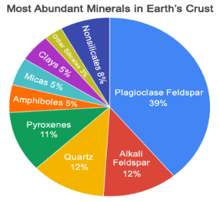
Fig 1.19 The Most Abundant Minerals in Earth's Crust: Known as the "common rock-forming minerals"
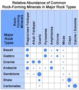
Fig 1.20
Rock-Forming Minerals in Major Rock Types:
This chart shows the relative abundance of the common rock-forming minerals in some of Earth's most abundant rock types. Basalt and gabbro account for most of the rock in the oceanic crust, granite (rhyolite) and andesite (diorite) represent abundant rock types of the continental crust. Sandstone, shale, and carbonates represent the common materials in the sedimentary cover of continents and ocean basins.
Minerals of the Oceanic Crust
As an example of the influence of just a few minerals, let’s consider the rocks of the oceanic crust. The oceanic crust is mainly composed of basalt and gabbro. These two rock types are made up mainly of plagioclase feldspar and pyroxenes, with smaller amounts of olivine, micas, and amphiboles. This small group of minerals makes up most of the rocks of the oceanic crust.
Minerals of the Continental Crust
As a second example, let’s consider the rocks of the continental crust. The continental crust is made up mainly of rocks with a granitic to andesitic composition. These rocks are composed mainly of alkali feldspar, quartz, and plagioclase feldspar, with smaller amounts of amphiboles and micas. This small number of minerals makes up most of the continental crust.
Minerals in the Sedimentary Cover
Both the oceanic and continental crusts are partly covered with a thin layer of sedimentary rocks and sediments. These consist mainly of clastic rocks such as sandstone, siltstone, and shale, along with carbonate rocks such as dolostone and limestone. These clastic rocks are composed of mainly quartz, clay minerals, and a small number of micas and feldspar minerals. The carbonate rocks consist primarily of calcite and dolomite. A small number of materials, composed of a small number of minerals, make up most of the sediment and sedimentary rocks that cover the continents and ocean basins.
Primary Minerals:
The primary minerals are those which are formed owing to the crystallization of the molten magma. We have already seen that the earth’s crust contains a dominant amount of oxygen (46.60%) followed by silicon (27.72%).
To achieve neutrality between the negatively-charged oxygen and the positively-charged silicon, there would be a greater tendency for silicon and oxygen to combine to form the basic compound, called the silicon-oxygen tetrahedron (SiO4). This explains the dominance (>90%) of silicate minerals (compounds containing silicon and oxygen, and one or more metal cations) in the earth’s crust.
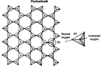
Fig. 1.21
A more complex linkage is in the sheet structure in which all tetrahedral (away from the sheet edge) share three oxygen ions with the neighboring tetrahedra. This further reduces the overall negative charge imbalance to one only. The sheet structures are phyllosilicates, of which micas are a typical example which is depicted in Fig. 1.21.The maximum linkage is attained in a 3-dimensional network in which all oxygen ions are shared between tetrahedra. Here each silicon is associated with 4 shared oxygen ions.This results in 4 positive and 4 negative charges for any tetrahedral unit, thereby achieving an electrically neutral structure. Such minerals with 3-dimensional structures are termed tectosilicates; typical examples of which are quartz and feldspars.
Secondary Minerals:
The secondary minerals are formed at the earth’s surface by weathering on the pre-existing primary minerals under variable conditions of temperature and pressure. During weathering, water accompanied by CO2 from the atmosphere plays an important role in processes, like hydrolysis, hydration, and solution. As a result, the primary minerals are altered or decomposed.
Feldspar + water → clay mineral + cations + anions + soluble silicaOne may observe that because of weathering, many elements are released into solution; a part of which may be used as a source of plant nutrients, a part may be leached out into the ground-water; still, another part together with other constituents (like CO2, H2O) of the environment may recombine to form secondary minerals.
The most commonly formed secondary minerals are clay minerals (e.g.illite, montmorillonite, and kaolinite) and iron and aluminum oxides.
References: