Unit - 7
Flow Through Pipes
When water flows in a pipe, it experiences some resistance to its motion, due to which its velocity and ultimately the head of water available is reduced.
This loss is due to friction.
2. Darcy – Weisbach formula
The loss of head in pipes due to friction is calculated from Darcy-Weisbach formula which is given by

Where, h f = loss of head due to friction,
f = co-efficient of friction, (a function of Reynolds number, Re)
f =  for Re varying from 4000 to 106
=  for Re < 2000 (laminar/ viscous flow)
L = Length of the pipe
V = Mean velocity of flow, and
D = Diameter of the pipe.
3. Minor Energy Loses
The loss of energy due to change of velocity of the flowing fluid in magnitude or direction is called minor loss of energy.
The minor loss of energy (or head) includes the following cases:
4. Loss of head due to Sudden Enlargement
Consider a liquid flowing through a pipe which has sudden enlargement as shown in fig.
 =
= 
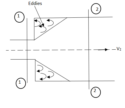
Fig no 1 Loss of head due to sudden contraction
5. Loss of head due to Sudden Contraction
Consider a liquid flowing in a pipe which has a Sudden Contraction in area as shown in fig.
 =
=  [
[  ]2
]2
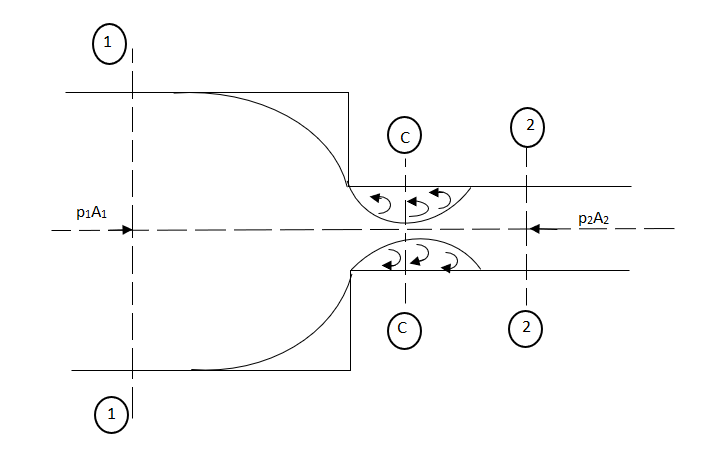
Fig no 2 Loss of head due to sudden contraction
6. Loss of head at the entrance of a pipe:
This is the loss of energy which occurs when a liquid enters a pipe which is connected to a large tank or reservoir.

7. Loss of head at the exit of pipe:
This is the loss of head due to the velocity of the liquid at the outlet of the pipe which is dissipated either in the form of a free jet or it is lost in the tank or reservoir.

8. Loss of head due to an obstruction in a pipe:
Whenever there is an obstruction in a pipe, the loss of energy takes place due to reduction of the area of the cross-section of the pipe at the place where obstruction is present.
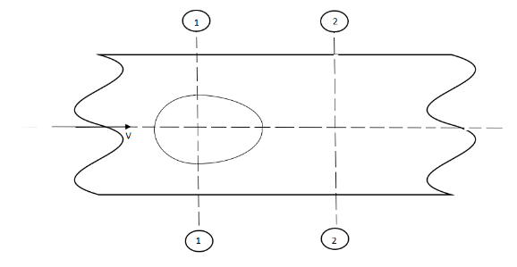
Fig no 3 Loss of head due to an obstruction in a pipe
a = Maximum area of obstruction
A = Area of pipe
V = Velocity of liquid in pipe
 [
[  ]2
]2
9. Loss of head due to bend in pipe:
When there is any bend in a pipe, the velocity of the flow changes, due to which the separation of the flow from the boundary and also the formation of eddies takes place.


10. Loss of head in various pipe fittings:
The loss of head in various pipe fittings such as valves, couplings etc. is expressed as


Key takeaways:
Major energy losses
This loss is due to friction.
Minor energy loss
The loss of energy due to change of velocity of the flowing fluid in magnitude or direction is called minor loss of energy.
Loss of head due to Sudden Enlargement
Loss of head due to Sudden Contraction
Loss of head at the entrance of a pipe:
Loss of head at the exit of pipe:
Loss of head due to an obstruction in a pipe:
Loss of head due to bend in pipe:
Loss of head in various pipe fittings:
Fig shows a horizontal pipe having steady flow.
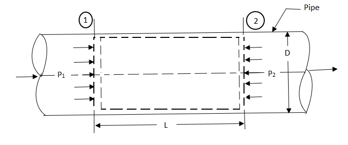
Fig no 4 Darcy wiesbatch equation
Consider control volume enclosed between section 1 and 2 of the pipe.
p1 = Intensity of pressure at section 1,
p2 = Intensity of pressure at section 2,
L = Length of the pipe, between section 1 and 2,
D = Diameter of the pipe,
f = Non-dimensional factor (Whose value depends on the material and nature of the pipe surface), and
hf= Loss of head due to friction.
Propelling force on the following fluid between the two section is = (p1 – p2) A
(Where, A = area of cross section of the pipe
Frictional resistance force = f ’ PLV
Where P = wetted perimeter, and
V = Average flow velocity
Under Equilibrium condition,
Propelling force = Frictional resistance force
i.e. (p1 – p2) A = f PLV2.
Dividing both sides by weight density W, we have
( ) A =
) A =  PLV2
PLV2
hf=  LV2
LV2
hf= 
=  *
*  *
* 
The ratio  is called the hydraulic mean depth or hydraulic radius, denoted by m (or R).
The term ( ) has dimensions of hf and thus the term
  is a non-dimensional quantity and let us replace it by another constant f.
 ------- 1
In case of a circular pipe,
Hydraulic mean depth, 
Substituting this value in equation 1, we get
 ---------2
(The factor f is known as Darcy coefficient of friction.)
Equation 2 is known as Darcy-Weisbatch equation.
Key takeaways
Darcy weisbatch equation

The small loss of pipeline flow is a major factor in calculating the flow, pressure, or reduction in power in piping systems. Piped fluid carries pressure and energy due to the force acting on it such as pressure and gravity. Just as certain system components can increase the strength of a liquid, there are systemic substances that work against this liquid and reduce its power, speed or intensity. Collisions and minor losses of pipes are the most contributing factors.
Below is a list of common piping elements and its kinematic energy
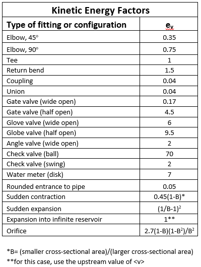
Fig no 5 Kinematic energy factor
The kinetic energy factor is used to calculate corrective head loss, energy loss in system objects. Corrective head loss, H LC can be calculated using the following equation.
H LC = V2/ 2g (∑ e v,i )
Where:
H Lc = Head configuration
v = Low velocity
g = Earth's gravity
∑e v,i= Total total kinetic energy in the system
Friction losses
Before being able to apply a small head loss in the equation, system loss due to collision should also be calculated.
Equation for friction losses
H L f = V2 / g R h (∑ L I ) f
H L f= Frictional head loss
v = Low velocity
g = Earth's gravity
R h = Hydraulic radius
∑ L I = Total length of pipes
f = Fanning conflict feature
Total Head loss
After the calculation of minimal loss and conflict loss is calculated, these values can be summarized to determine the total head loss.
The total number of head loss, H L can be simplified and rewritten as:
H L = v 2 / 2 g R h [( 2 ∑ L I ) f + R h ( ∑ e v , I )]
H L= Deceptive head loss
v = Low velocity
g = Earth's gravity
f = Fanning conflict featur
Once calculated, the total head loss can be used to solve the Bernoulli Equation and to obtain unknown system values.
Key takeaway:
H LC = V2/ 2g (∑ e v,i )
H L f = V2 / g R h (∑ L I) f
H L = v 2 / 2 g R h [(2 ∑ L I) f + R h( ∑ e v , I )]
Total head = 
Key takeaways:
Total head = 


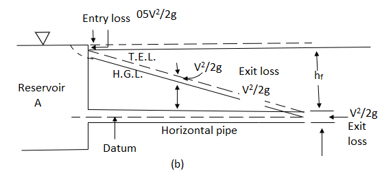
Fig no 6 Hydraulic gradient line
Key takeaways
If a line is drawn joining the piezometric levels at various points, the line so obtained is called the ‘Hydraulic gradient line.
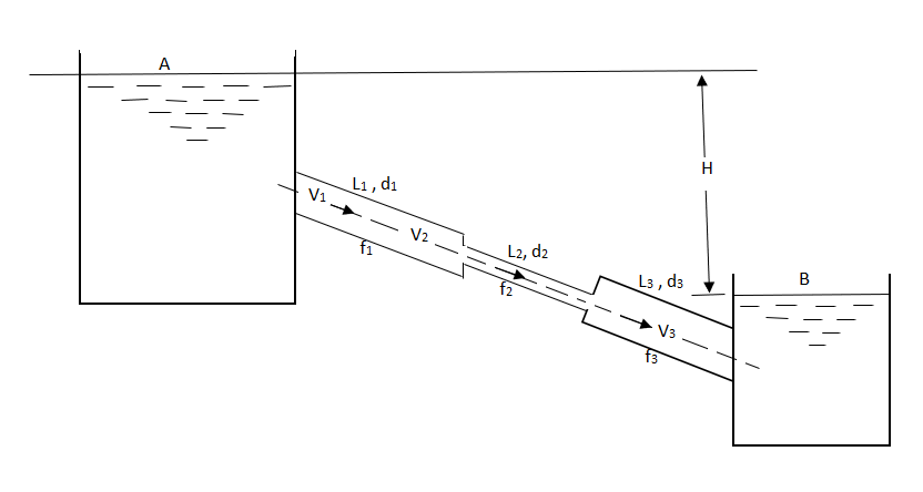
Fig no 7 Pipes in series
L1, L2,L3 = Length of pipes 1, 2 and 3 respectively
d1, d2, d3 = diameters of pipes 1, 2, 3 respectively
v1, v2, v3 = velocity of flow through pipes 1, 2, 3
f1, f2, f3 = coefficients of frictions for pipes 1, 2, 3
H = difference of water level in the two tanks
The discharge passing through each pipe is same


The difference in liquid surface levels is equal to the sum of the total head loss in the pipes.

If minor losses are neglected, then above equation becomes as

Key takeaways
The difference in tanks when pipe connected in series

L1= length of pipe 1 and d1 = diameter of pipe 1
L2 = length of pipe 2 and d2 = diameter of pipe 2
L3 = length of pipe 3 and d3 = diameter of pipe 3
H = total head loss
L = length of equivalent pipe
d = diameter of equivalent pipe
Total head loss in the compound pipe, neglecting minor losses
 --------- 1
f1 = f2 = f3 = f


Substituting these values in equation 1, we have

 --------- 2
Head loss in the equivalent pipe, 
Where 
 --------- 3
Head loss in compound pipe and in equivalent pipe is same hence equating equations 2 and 3, we have

or 
 --------- 4
Equation 4 is known as Dupuit equation
Key takeaways:
When there is an equivalent pipe the equation use is a

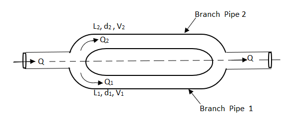
Fig no 8 Pipes are connected in parallel

In this arrangement, the loss of head for each branch pipe is same.
Hence, Loss of head for branch pipe 1 = Loss of head of branch pipe 2

Key takeaways
When pipes are connected in parallel loss of head for branch pipe1 = loss of head of branch pipe 2

Key takeaways:
Lateral flow also known as lateral flow immune chromatographic assays or rapid tests, are simple devices intended to detect the presence of a target object in a liquid sample without the need for special and expensive equipment.
These tests are widely used in clinical home testing, point-of-care care, or laboratory use. For example, a home pregnancy test is a lateral flow test that detects a particular hormone. These tests are simple, economical and usually show results in about 5-30 minutes.
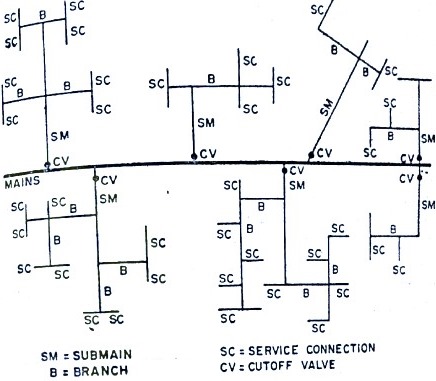
Fig no 9 Dead Water Supply System
Advantages of the Dead End System
Disadvantages
Key takeaways:
The last dead system, the name itself means that it contains items that are no longer in the pipeline system. Therefore, water does not flow continuously in the dead end system. In this system the entire pipeline network is divided into several smaller networks. That is the main line, sub mains, branch lines and app connections.
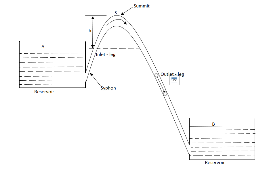
Fig no 10 Siphons
Key takeaways:
A Syphon is a long bent pipe employed for carrying water from a reservoir at a higher elevation to another reservoir at a lower elevation when the reservoirs are separated by a hill or a high level ground
Consider a pipe AB connected to a high level storage tank as shown in fig.
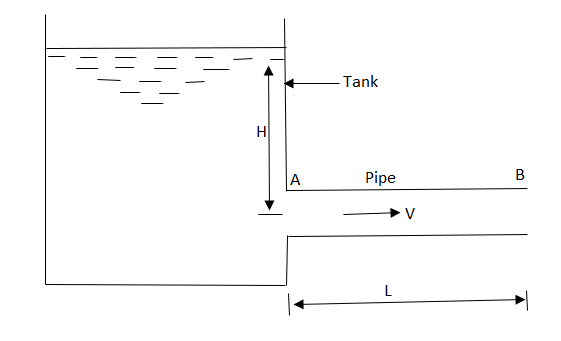
Fig no 11 Power transmission through pipes
H = Head of water available at the inlet of the pipe, m,
L = Length of the pipe, m,
D = Diameter of the pipe, m,
V = Velocity of water in the pipe, m/s,
f = coefficient of friction, and
hf = Loss of head in the pipe AB, due to friction, m,
WQ = weight of water flowing through the pipe per second = WAV
(where, Q = discharge of water through the pipe, m3/s)
And, net head water available at B (neglecting minor losses)

Also, the efficiency of transmission,

And power, 


It is evident from above equation that power transmitted depends upon the velocity of water (v), as the other things are constant.
Hence, power Transmitted will be maximum when


It means that power transmitted through the pipe is maximum when head lost due to friction in the pipe is equal to  of the total supply head.
Key takeaways
The transmission of power through pipes carrying water or other liquids is commonly used for working of several hydraulic machines.
It means that power transmitted through the pipe is maximum when head lost due to friction in the pipe is equal to  of the total supply head.
Network Pipeline Analysis
Hardy-Cross method
This approach involves considering the distribution of flow in a network in such a way that the law of continuity is satisfied at each intersection. Adjustments to this estimated motion are calculated sequentially for each loop in the network, until the adjustment is reduced to an acceptable size.
If Qa is the imaginary flow and Q is the actual pipe flow, the d correction is given by
d = Q-Qa; or Q = Qa + d
Now, expressing the head loss (HL) as
HL = K.Qx
We have, head loss in the pipeline
= K. (Qa + d) x
= K. [Qax + x.Qax-1d + ......... small words)
= K. [Qax + x.Qax-1d]
Now, around the closed loop, the summary of head loss should be zero.
\ SK. [Qax + x.Qax-1d] = 0
or SK.Qax = - SKx Qax-1d
Since the d is the same for all loop pipelines, it can be extracted from the summary.
\ SK.Qax = - d. SKx Qax-1
or d = -SK.Qax / Sx.KQax-1
Since d is given the same symbol (direction) across all loop pipes, the denominator of the above equation is taken as the total sum of each item in the summation. Therefore,
Or d = -SK.Qax / S l x.Kaxax-1 l
Or d = -SHL / x.S lHL / Qal
Where HL loses its head with the Qa-assumed flow.
The numerator in the above figure is an algebraic total of head loss in various closed loop pipes connected to the imaginary flow. Since the direction and magnitude of the flow of these pipes have already been considered, their head loss in sequence by signing can be easily calculated after considering their width. The total amount of KQax-1 or appropriate HL / Qa is calculated. Eventually the value of d is found in each loop, and the assumed flow is adjusted. Repeated adjustments are made until the desired accuracy is achieved.
Key takeaways
Analysis of the water distribution system includes finding the amount of flow and head loss in the various pipeline lines, as well as the remaining residual pressure. In any plumbing network, the following two conditions must be met:
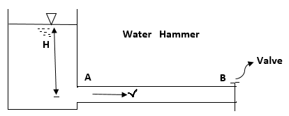
Fig no 12 Water hammer
Control measures:
Key takeaways:
This high pressure wave will be passed along the pipe by a velocity equal to the velocity of the sound wave and can create a noise called Knocking,
And this high pressure wave has the effect of moving the walls of the pipe, hence the name water hammer.
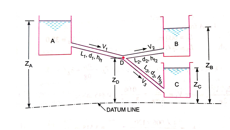
Fig no 13 Branched pipes
Key takeaways
When three or more reservoirs are connected by means of pipes having one or more junctions, the system is called branching pipe system.
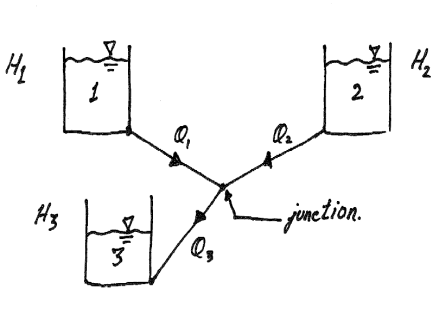
Fig no 14 Three reservoir problems
The following are the necessary conditions for any network pipes:
The value of R depends upon the length of pipe, diameter of pipe and coefficient of friction of Pipe. The value of n for turbulent flow is 2.
We know that


Therefore, 
Key takeaways
A pipe network is an interconnected system of pipes forming several loops of circuits.
The pipe network is shown in figure.
The examples of such networks of pipes are the municipal water distribution system in cities and laboratory supply system.
Examples:
Q.1 A pipe of diameter 300mm diameter suddenly converges t 150mm diameter, due to this the pressure changes from 95 kN/m² to 50 kN/m², if coefficient of contraction I 0.65, calculate the flow rate carried by the pipe.
Soln.:
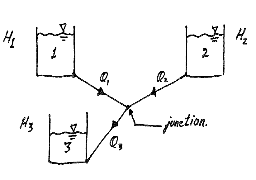
Given:
d=300 mm = 0.3m,
d₂ = 150 mm = 0.15m.
P₁ = 95 kN/m², P₂ = 50 kN/m², Cc = 0.65
To find: Q


By continuity equation


Loss due to sudden contraction

By Bernoulli’s equation

Z1= Z2


Discharge

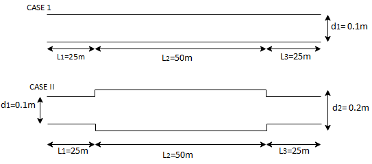
Q. 2 Three pipes of diameter 10 cm each, and having length 25 m, 50 m and 25 m are joined together in series. Water flows through this pipe at 2.15 m/s. The central pipe of length 50 m is replaced by 20 cm diameter pipe. The change in section due to replacement at both ends is sudden. Assuming friction factor f-0.032 and Cc is 0.62, find the net saving in head
Soln.:
Given: Three pipes of diameter d, 10 cm = 0.1 m=d,
L₁25 m, L=50 m, L=25 m. V₁ = 2.15 m/s V,
Central pipe L50 cm replaced by d, = 20 cm = 0.2 m.
f=0.032, C-0.62
To find: 1) Net saving in head.
Area

 0.031416 m
Discharge


Case I
Head loss due to friction (Considering total length)

Case II
Head loss= [ head loss due to friction] + [Head loss due sudden expansion]+[ Head loss due to friction] + [Head loss due to contraction] + [Head loss due friction]


Net saving in head = [head lost] case I –[ head lost] case II
= 7.5392-4.1084 = 3.4308 m
Q. 3 A 50m long pipe of 10cm diameter carries water at a velocity 5m/s it has been decided to replace 25m of above pipe by enlarged diameter pipe of 20cm, the change of section being sudden, Assuming f= 0.02 and coefficient of contraction Cc=0.62, find saving in the loss due to replacement of pipe.
Soln.:
Given:
L=50 m, L₁= L = 25 m. Cc = 0.62,
f = 0.02 d=10 cm = 0.1 m,
d, = 20 cm = 0.2 m, d₂ = 0.1 m
To find: Saving head loss
(1) Head loss in initial pipe of L=50 m
Area


2) Head lost due to sudden contraction:

Using continuity equation


Head loss due friction


Total head loss = head loss due to friction + head loss due to contraction

Solving in head loss


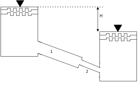
Q.4 Two reservoir at different elevations are connected with a compound pipe of 1 km total length; consisting of two sections. First section connect to higher level reservoir is 500 m long and 200 mm in a diameter and other half is connected to lower level reservoir and has 100 mm diameter. Darcy Weisbach friction factors for the pipes are 0.019 and 0.02 respectively. If velocity of flow of water in the second section is 1.5 m/s. Find the difference in water levels in the reservoirs considering all losses. Find the rate of flow of water also. Find diameter of single uniform diameter pipe replace the above pipeline to carry same discharge. Take f = 0.018 for the pipe.
Soln.:
Given:
d₁= 200 mm = 0.2 m
f₁ = 0.019 d₂ = 100 mm = 0.1 m
f₂ = 0.02
L = 1 km
By continuity equation,
A₁V₁ = A₂V₂


Case I:
Major losses = Loss due to friction Loss due to friction in pipe 1 in pipe 2


Minor losses = Loss at entry + Loss due to contraction + loss at exit


Total losses = Major losses+ Minor losses

Case II: New pipe with uniform diameter.


The diameter of single equivalent pipe is 114.16 mm.
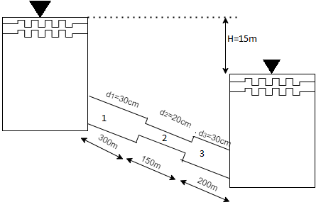
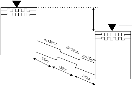
Q.5 The difference in water level, between two tanks which are connected by three pipes in series is 15 m. length and diameter of these pipes are 300 m, 150 m, 200 m and 30 cm, 20 cm, 30 cm respectively. Find the discharge through the pipeline and tabulate all losses if f for the three pipes to be taken as 0.02, 0.025 and 0.03.
Soln.:
Given:
H=15 cm, d,= 30 cm = 03 m. f = 0.02
L₁= 300 m. d2 = 20 cm = 0.2 m.
F= 0.025,
L = 150 m,
d3 = 30 cm=0.3 m.
f = 0.03,
L = 200 m
Let V. V, and V, are the velocities in the 1", 2, and 3 pipe.
by continuity equation,


Case 1: Major Losses-Frictional loss in pipe 1+ Frictional loss in pipe 2+ Frictional loss in pipe 3

Put value we get,

Minor losses = loss at entry + loss due to contraction between pipe 1 and 2 + loss due to expansion between pipe 2 and 3 + loss at exit


Total loss = major losses + minor losses


Rate of flow of water

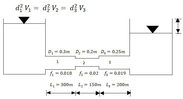
Q. 6 Three pipes 300 m, 150 m, 200 m long having diameters 300 mm, 200 mm and 250 mm respectively are connected in a series in the same order. Pipe having 300 mm diameter in connected to the reservoir. Water level in the reservoir is 15 m above the pipe are 0.018, 0.02 and 0.019. Determine the flow rate, magnitude of loss in each pipe section, and the diameter when the three pipes are replaced by a single pipe (f = 0.016) to give the same discharge. Neglect the minor losses.
Soln.
Let V, V, and V, are the velocities in the pipe 1, 2, 3 respectively.
By continuity equation


Major loss = hf1+hf2+hf3


Flow rate

Head loss in each pipe


Diameter when three pipes are replaced by single pipe
Using Dupit’s equation


Q.7 Three pipe: 300 m long, 30 cm diameter; 150 m long, 20 cm diameter; 200 m long, 25 cm diameter; are connected in series in the same order between two reservoirs. Darcy Weisbach friction factors for the three pipes are 0.018, 0.02 and 0.019 respectively. Determine the flow rate, if the difference of elevations of water levels in the two reservoirs is 15 m. Account for all losses: contractions and expansions are suddenly. Also determine magnitude of each loss in flow between the reservoir. Use the given table. Loss coefficient for sudden contraction:
Ag/A1 | 0.2 | 0.3 | 0.4 | 0.5 | 0.6 | 0.7 |
K | 0.41 | 0.36 | 0.3 | 0.24 | 0.18 | 0.12 |
If the three pipes are replaced by a single pipe (f = 0.016 to give the same discharge), determine the diameter of pipe.
Soln.:
Given:
L₁ = 300 m,
f₁ = 0.018,
L₂=150 m. f₂ = 0.0,2
L₁ = 200 m, f = 0.019
d₁ = 30 cm = 0.3 m,
d₂ = 20 cm = 0.2 m, d3 = 25 cm = 0.25 m.
Major losses = Frictional loss in pipe 1 + Frictional loss in pipe 2+ Frictional loss in pipe 3


Case I
Minor losses= loss due to entrance + loss due to contraction + loss due to expansion+ loss due to exit

By continuity equation


The value K is calculated by interpolation method

Put the value V1, V2 and V3 and K in equation of minor losses


Now magnitude
Major loss


minor loss

2. Loss due to contraction

3. Loss due to expansion

4. Loss due to exit

Case II
Diameter when the compound pipe is replaced by a single pipe


The diameter of new pipe i2 22.62 m
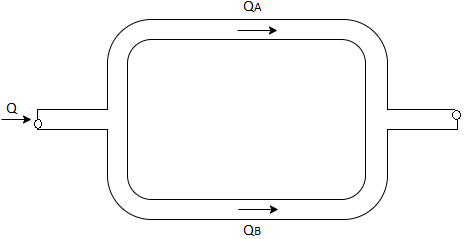
Q.8 two pipes running parallel are joined end to end the total discharge to be carried by the system is 2000 liter/sec Determine the discharge carried by each pipe particular of pipes are as follows:
Pipe | Friction factor | Diameter | Length |
A | 0.018 | 0.60 | 1000 |
B | 0.020 | 0.80 | 800 |
Solution:
Given:
Q= 2000 liter/sec
For parallel pipe


Discharge through pipe A


The discharge through pipe


Q.9 Two pipes of 20cm and 30 cm diameter are laid in parallel to pass a total discharge of100 l.p.s. each pipe is 250 m long. Determine discharge through each pipe. Now these pipes are connected in series to connect two tanks 500 m apart to carry same total discharge. Determine water level difference between the tanks neglect minor losses in both cases. Take f=0.02 for both pipes
Solution:
Given:
d1= 20cm= 0.2 m
d2 = 30cm= 0.3 m
Q= 100lps= 0.1 m^3/sec
L = 250 m
f = 0.02 for both pipes
To find: H
Case I
For parallel pipe head loss remain same in both pipes


For parallel pipe


Discharge


Case II
For pipe in series


Water level difference between tanks is 14.61 m
References: