Unit - 1
Simple Stresses and Strains
1. Stress
In mechanics, stress is defined as a force applied per unit area. It is given by the formula
σ=F/A
Where,
σ is the stress applied
F is the force applied
A is the area of force application
The unit of stress is N/
Stress applied to a material can be of two types. They are:
2. Strain:
According to the strain definition, it is defined as the amount of deformation experienced by the body in the direction of force applied, divided by initial dimensions of the body. The relation for deformation in terms of length of a solid is given below.

Where,
 is the strain due to stress applied
 is the change in length
L is the original length of the material.
The strain is a dimensionless quantity as it just defines the relative change in shape.
Depending on stress application, strain experienced in a body can be of two types.
Key takeaway:
Maximum principle strain theory is also known as St. Venant’s theory
This theory state as that the material subjected to complex stresses will fails when the maximum principle strain in it reaches the value of strain at yield point in a simple tensile test on materials
If  are the principle stresses acting on three mutually perpendicular planes then maximum principle strain (e1) for no failure condition is given by,


 where e1 must be positive and e3 must be negative
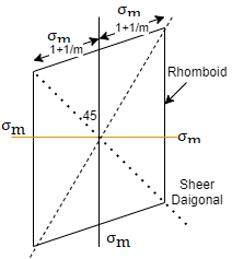
This equation shows the maximum principle strain  may be greater than
  which is unexpected condition in machine component so this theory is very little consideration
For two direction stress maximum principle strain theory is represented is shown in fig which is rhombus failure envelope.
Key takeaway:


1. Stress diagram
The internal resistance set up per unit cross sectional area is called as stress. It is denoted by 

In the equilibrium condition the internal resistance R is equal to an external load P
i.e., R=P

Where

P = load acting on the body
A = cross sectional area of the body
2. Strain Diagram:
Strain is simply a measure of deformation produced in a member due to the loads acting on it.
It is defined as the ratio of change in dimension to the original of the member

Key takeaway:

1. Elasticity:
It is property of a material by virtue of which its regions its original size and shape after deformation when the loads causing deformation are removed
2. Plasticity:
Lack of elasticity is called plasticity
The plasticity of a material is the ability to change its shape without destruction under the action of external load and to regain the shape given to it when the forces are removed.
1. Stresses:
It is the force applied per unit area which results in the increase in length (or area) of a body. Objects under tensile stress become thinner and longer.
2. Compressive Stress:
It is the force applied per unit area which results in the decrease in length (or area) of a body. The object under compressive stress becomes thicker and shorter.
3. Shear stress:
When two equal opposite and parallel force acting tangential to the surface of the body is called as shear stress
2. Strains:
It is the change in length (or area) of a body due to the application of tensile stress.
2. Compressive Strain:
It is the change in length (or area) of a body due to the application of compressive stress
When we study solids and their mechanical properties, information regarding their elastic properties is most important. These can be obtained by studying the stress-strain relationships, under different loads, in these materials.
3. Shear strains:
The measure of small distortion of the block caused by the shear force is called shear strain
Key takeaway:
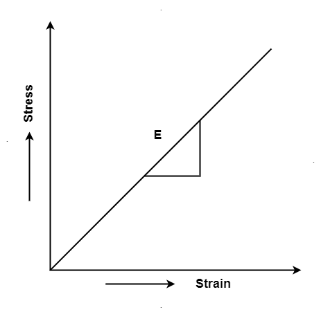
Hooke's law states that the strain of the material is proportional to the applied stress within the elastic limit of that material.
When the elastic materials are stretched, the atoms and molecules deform until stress is been applied and when the stress is removed, they return to their initial state
i.e., σ = E
Where,
σ is the stress
E is the modulus of elasticity also known as Young’s modulus
ε is the strain
When the stress is removed from the material, there are two types of deformation that can take place: plastic deformation and elastic deformation
Key takeaway:
Stress-Strain Diagram for mild steel (ductile material)
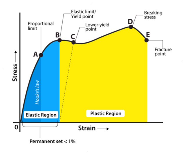
Explaining Stress-Strain Graph
The stress-strain graph has different points or regions as follows:
Proportional limit
Elastic limit
Yield point
Ultimate stress point
Fracture or breaking point
(i) Proportional Limit
It is the region in the stress-strain curve that obeys Hooke’s Law. In this limit, the ratio of stress with strain gives us proportionality constant known as young’s modulus. The point OA in the graph is called the proportional limit.
(ii) Elastic Limit
It is the point in the graph up to which the material returns to its original position when the load acting on it is completely removed. Beyond this limit, the material doesn’t return to its original position and a plastic deformation starts to appear in it.
(iii) Yield Point
The yield point is defined as the point at which the material starts to deform plastically. After the yield point is passed, permanent plastic deformation occurs. There are two yield points (i) upper yield point (ii) lower yield point.
(iv) Ultimate Stress Point
It is a point that represents the maximum stress that a material can endure before failure. Beyond this point, failure occurs.
(v) Fracture or Breaking Point
It is the point in the stress-strain curve at which the failure of the material takes place.
Key takeaway:
It is defined as the ratio of the actual axial load and the original cross-sectional area of the specimen.

Working stress is the maximum allowable stress to which a material is subjected during its service load
For a safety of a structure, it is very essential that the working stress should be within the elastic limit of the material
The ratio of the ultimate stress to the working stress for a brittle material is called factor of safety.

The ratio of the yield stress to the working stress for a ductile material is called factor of safety

In designing to resist accidental loads sufficient reserve strength is required to be ensured which is called out by taking a suitable factor is called as factor of safety
Strain in the direction at right angles to the direction of applied force is known as lateral strain.
It is the ratio of change on lateral dimension to the original lateral dimension of the member.
Lateral strain = 
For rectangular bar
Lateral strain  or
or =
= 
When a body is subjected to simple tensile stress within its elastic limits then there is a change in the dimensions of the body in the direction of the load as well as in the opposite direction.
When these changed dimensions are divided with their original dimensions, longitudinal strain and lateral strain are obtained.
The ratio of the lateral strain to the longitudinal strain is called Poisson’s ratio.
It is represented by the symbol “µ”. Poisson’s ratio is maximum for an ideal elastic incompressible material and its value is 0.5.
For most of the engineering materials, Poisson’s ratio lies between 0.25 and 0.33. It has no units.
When a body is subjected to external forces on its face, there will be a change in its volume
The Ratio of change in volume to the original volume is known as volumetric strain
It is denoted by  .
.

Where  change in volume and
 original volume

By partial differentiation


i.e., 
Volumetric Strain is the algebraic sum of all axial or linear strains
i.e., 
Where, 


Different elastic constants are as follows:
1. Young’s Modulus
According to Hooke’s law, when a body is subjected to tensile stress or compressive stress, the stress applied is directly proportional to the strain within the elastic limits of that body. The ratio of applied stress to the strain is constant and is known as Young’s modulus or modulus of elasticity.
Young’s modulus is denoted by letter “E”. The unit of modulus of elasticity is the same as the unit of stress which is megapascal (Mpa).
1 Mpa is equal to 1 N/mm2.

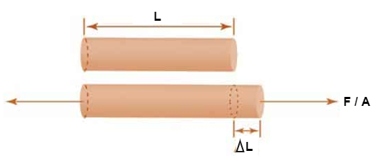
Fig: Body Subjected to Tensile Stress
2. Bulk Modulus
When a body is subjected to mutually perpendicular direct stresses which are alike and equal, within its elastic limits, the ratio of direct stress to the corresponding volumetric strain is found to be constant.
This ratio is called bulk modulus and is represented by letter “K”.
Unit of Bulk modulus is Mpa.

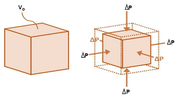
Fig: Volumetric Change of Body
3. Rigidity Modulus
When a body is subjected to shear stress the shape of the body gets changed, the ratio of shear stress to the corresponding shear strain is called rigidity modulus or modulus of rigidity.
It is denoted by the letter’s “G” or “C” or “N”.
Unit of rigidity modulus is Mpa.

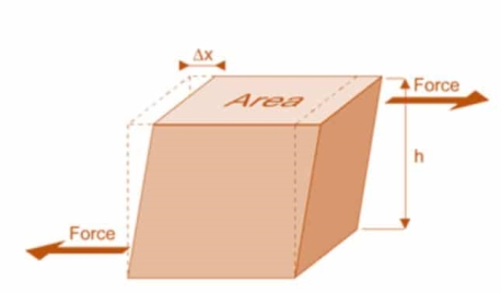
Fig: Shear Deformation of Body
4. Poisson’s Ratio
When a body is subjected to simple tensile stress within its elastic limits then there is a change in the dimensions of the body in the direction of the load as well as in the opposite direction.
When these changed dimensions are divided with their original dimensions, longitudinal strain and lateral strain are obtained.
The ratio of the lateral strain to the longitudinal strain is called Poisson’s ratio.
It is represented by the symbol “µ”. Poisson’s ratio is maximum for an ideal elastic incompressible material and its value is 0.5.
For most of the engineering materials, Poisson’s ratio lies between 0.25 and 0.33. It has no units.
5. Relationship between Elastic Constants


A composite bar product of bars of various substances rigidly constant collectively in order that each bars strain collectively below outside load.
Since traces within side the bars are same, the stresses within side the bars rely on their Young’s modulus of elasticity. In different words, a stiffer bar will proportion predominant element of outside load.
In a composite machine the 2 bars of one-of-a-kind substances aren't joined collectively, however they assist a 0.33 inflexible bar.
Load utility at the 0.33 inflexible bar is such that extrude in period of each bar is the same, generating one-of-a-kind stresses in bars.
A meeting of bars, located co-axially, however having one-of-a-kind lengths.
Bar of Varying Sections. The strain and deformation of duration prompted in every of the sections of the bar are different, even though the axial load performing at the bar is the same.
The derivation is accompanied with the aid of using the precept that, Total Change in duration, dL = Sum of Change in duration of Section 1, Section 2 and Section 3.
A composite bar fabricated from two bars of various substances rigidly constant collectively in order that both bars stress collectively be neat outside load.
In a composite gadget the two bars of various substances aren't joined collectively, however they assist a 3rd rigid bar.
The quantity of any square solid, together with a cube, is the area of its base (period instances width) accelerated with the aid of using its height: V = l × w × h. Therefore, if a pass section is parallel to the pinnacle or backside of the solid, the area of the pass-section is l × w
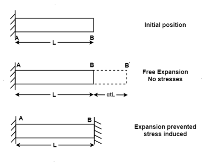
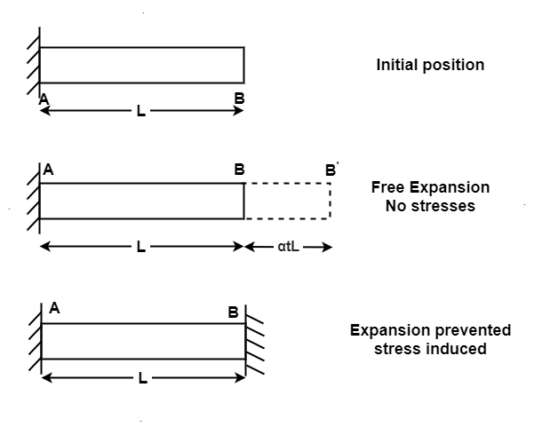
When the expansion or Contraction of the member due to temperature variation is prevented the stresses induced in the member is called Temperature stresses
When the Temp is rise, the stresses induced in the member are compressive in nature.
When Temp falls, the stresses induced are Tensile in nature
We know, 


Where, = Coefficient of thermal expansion in 1 C or 1
 k
k
T = Temperature Variation in  or K.
or K.
E = Young’s Modulus,
1. Strain energy
When a load is applied on an elastic body it gets deformed i.e., the work is done by the load on the body
This work done is stored in a body is called as strain energy or resilience
When the load is removed the body regains to its original position because of stored energy
It can be easily visualized in springs when the springs is loaded it gets compressed and regain to its original position immediately when the load is removed
The amount of the strain energy stored in a body is depended on the type of loading i.e., axial load, bending load, shear load and torsion load etc.
2. Resilience:
The energy which is stored in a body within an elastic limit is called a strain energy or resilience it is denoted by U
3. Stress due to gradually applied load:
When a body is subjected to the gradually applied load, the stress increases from zero to the maximum value gradually
Let p= gradually applied load
 L = Extension due to load
 = maximum stress induced in the member


Strain energy stored in body

But Work done = Strain Energy stored


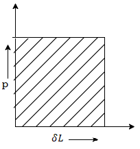
4. Stress due to suddenly applied load
When the load acting on a body is sudden the body gets deformed immediately after applying load for e.g., Weight of truck enter on weighing machine is an example of sudden load
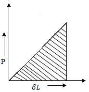
Let P= suddenly applied load


Work done by load = Area under curve
= P. 
Strain energy stored in a body = 
But work done = strain energy stored


Stress due to sudden load is twice the stress due to gradually applied load.
4. Stresses due to Impact load
When a load applied on a body is falls from a certain height is called as impact or falling load
Consider a member is fixed at its top and a collar is attached to its lower end as shown in fig.
Let, W= weight of movable load
H = height of fall
L= length of member
A = cross sectional area
 L: = Deformation of length
 = Instateneous stress
Work done by external movable load = W (h+ )
)

But work done by load = Energy Stored in member


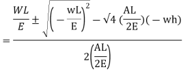
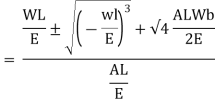
Multiplying both numerator and denominator by E/2E we get,

Maximum instantaneous stress

But 


The dimensionless ratio  is called as load factor and it is denoted by n

5. Shock loading – simple application
Shock loading:
Shock loading present sainted resting set of problems to the designed engineer. In the engineering com-munity, layout for static loading traditionally has been the maximum commonly used design procedure.
Designing for surprise loading, however, requires change of thinking in ever all areas.
The objectives of this discussion are to introduce the simple principles of surprise loading and to consider their effect upon the intently of structure
Static loading happens whilst a pressure is slowly applied to a member.
This is a gradual or constant loading system this is equivalent to loading them ember over a length of 1min.
Designing for static loading traditionally has been the method used for an extensive type of components, inclusive of buildings, water towers, dams.
Fatigue loading happens whilst the member stories alternating, repeated, or fluctuating stresses.
Fatigue loading generally is classified through the number of loading cycles at the member and the stress level.
Key takeaways:
References: