Unit - 5
Shear Stresses
1. Shear stresses:
The shear force at the cross section of a beam is defined as the algebraic sum of all the unbalanced vertical forces either left or right of the section.
SF = (∑ Fy) L = (∑ Fy) R
Sign convention for shear force:
An upward force to the left of section or downward force to the right of a section will be considered as a positive shear force.
When the force is downward to the left side of section and upward on the right of a section, will be considered as a negative shear force.
2. Derivation of formula
Consider a small portion ABCD of length dx of a beam with bending moment varying from m to m=dm due to udl over its length dx
The distribution of compressive stresses due to bending moment shown in fig
Let
M = bending moment at AB
M + dM = bending moment at CD
F = shear force at AB
F+ dF = shear force at CD
Consider element strip EF at a distance y from the neutral axis as shown in fig.

Let
σ = bending stress across AB at a distance y from neutral axis
σ + d σ = bending stress across
I = moment of inertia
By using flexural formula

On face AB, 
On face CD, 
Face acting across AB 
Similarly, force acting across CD, 
Net unbalanced force on the strip

The load unbalanced force F above neutral axis can be found out by integrating from 0 to d/2


But ∫ y x dA= first moment of area under consideration from neutral axis= Ay
F = dM/ I x Ax y
This unbalanced force is balanced by a shearing stress 𝜏 acting along the length dx and width b,
Shear stress = shear force/ shear area


But 

Where,
S = shear force at the section under consideration
A = area above or below the layer under consideration
y = distance of centroid of area under consideration from neutral axis
b = width at the layer under consideration
I = moment of inertia of the section.
Key takeaway:
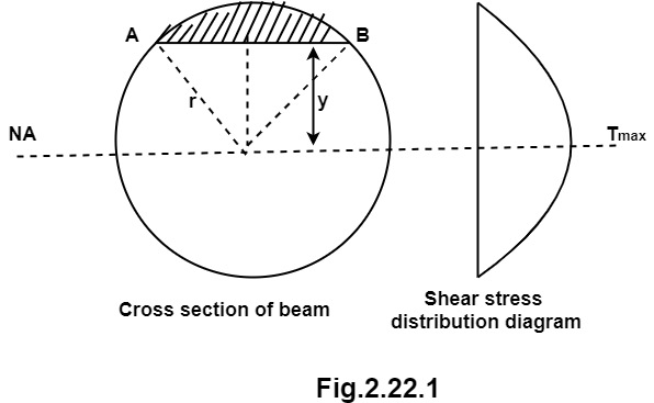
1. Shear stress distribution over a circular section:
Consider a circular section of diameter d as shown in fig.
Diagram

The shear stress on a layer AB at a distance is given as,

Width of strip AB in a circular section

Where, r= radius of circular section
Area of shaded strip =
Moment of area about neutral axis =
The moment of whole shaded area about neutral axis

But 

Again, 
Squaring both side
2b db = 4(-2y) dy

Substituting the value of y. dy in equation (i)

We know that, when y= r. and b = 0
The limit of integration may be changed from y to r, from b to 0 in equation (i)


Now substituting Ay in shear stress formula


Observations from above equation
From Equation (iii) shear stress 𝜏 increases as y decreases
At y = 𝜏 𝜏 = 0
At y = 0 𝜏 is maximum

Put r= d/2

put I = 𝛑/64 d4


Therefore,


2. Shear stress distribution over a rectangular section:
Consider a beam of a rectangular section of width b and depth d as shown in fig.

Shear stress at any layer CD of beam at a distance y from the neutral axis

Where,
S = shear force at the section
A = Area of beam above y
y = Distance of centroid of shaded area from neutral axis
I = Moment of inertia of the section
b = Width of section CD
Area of shaded portion 
Distance of centroid of area from neutral axis


Moment of inertia 
Shear stress at any layer CD


From above equation we can observe that,
𝜏 increases as y decrease
Variation of 𝜏 is parabolic as the equation in of second degree
When y = d/2, 𝜏 = 0
When y= 0, 𝜏 is maximum
The variation of shear stress across the depth of the beam is parabolic.
Shear Stress
At top and bottom, y= d/2 
At neutral axis, y= 0


Where

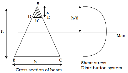
3. Shear stress distribution over a triangle section:
Consider a beam of triangular section ABC of base b and height h as shown in fig Shear stress on a layer DE at a distance y from neutral axis.

Consider a section DE at distance x from apex A
Width of the trip DE (say b)

By similarity of triangle


Area of shaded portion ADE

Distance of centroid of area above layer DE

Shear stress at DE


Observation from above equation the variation of shear stress with respect to x is parabolic
At x= 0, 
At bottom x=h, 
At a neutral axis x=2/3 h


For maximum shear stress 
h-2x = 0
x= h/2
Maximum shear stress occurs at h/2 for triangular section


For triangle section maximum shear stress occurs at h/2 and is on neutral axis
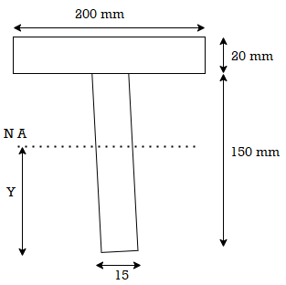
4. Shear stress distribution over a T section:
Draw shear stress distribution on a T section with flange 150 x 15 deep and flange 200x 20 wide. The section is symmetric at vertical axis the shear force applied is 110KN

Solution:
Given:
T section
Shear force S= 110 KN
To find: Shear stress distribution
Position of neutral axis

A1= 15x 150= 2250 mm2
y1 = 150/2 = 75 mm
A2 = 200x20 = 4000mm2
y2 = 150+ 10 = 160mm

y = 129.4 mm
moment of inertia
I = Ixx1+ Ixx2
[
= 14.756x106 mm4
Shear stress at extreme top and bottom is zero
Shear stress at junction
Area above junction A = 200x 20 = 4000mm2
C.G of area above junction wrt.NA
y = (170-129.4)-20/2 = 30.6 mm
Width of junction b1= 200mm and b2 = 15mm


References: