Unit-1
Analysis of Indeterminate Structure by force methods
The pressure approach of analysis additionally knows because the approach of steady deformation makes use of equilibrium equations and compatibility situations to decide the unknowns in statically indeterminate systems. In this approach, the unknowns are the redundant forces. For indeterminate systems, Statics (equilibrium) on my own isn't always enough to behavior structural analysis. Compatibility and fabric facts are essential.
Number of unknown Reactions > Number of equilibrium equations
Advantages:
Disadvantages:
2. Methods of analysis:
3. Techniques of analysis there are most important techniques:
Flexibility Method or Method of Consistent Deformation:
4. Static Indeterminacy
The Static Indeterminacy (SI) for beams and frames is described as,
SI = nu — ne
Where,
nu = Number of unknown assist reactions
ne = Number of equations of equilibrium
In fashionable for a -dimensional shape, there are 3 equations of equilibrium (ne = 3) and for a 3-dimensional shape there are six (ne = 6).
For a truss, static indeterminacy entails each outer and inner indeterminacy due to the inner individuals in a truss.
Static indeterminacy (SI) within side the case of a truss is described as,
SI = b + r — 2j
Where,
b = Number of individuals within side the truss
r = Number of reactions on the supports
j = Number of joints within side the truss
5. Sign Conventions
1) Static Calculations
∑F x = 0, ∑F y = 0 & ∑M = 0
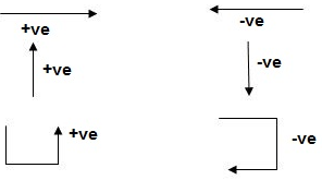
Fig.1.1 Static calculation
2) For Structural Actions
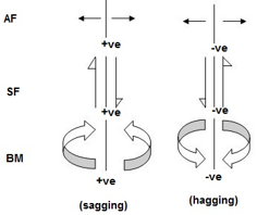
Fig.1.2 Structural action sign convention
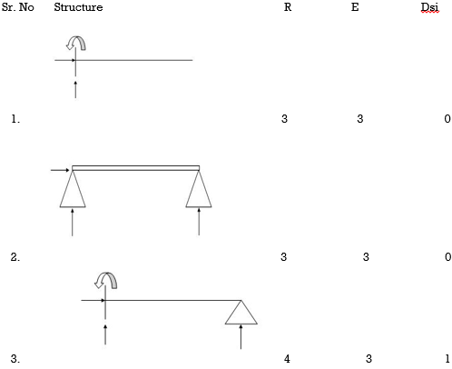
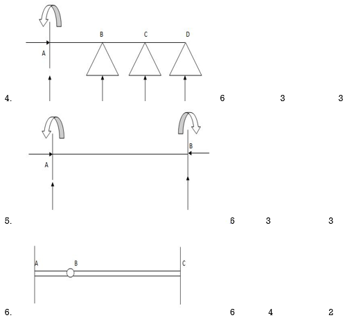
6. Degree of static indeterminacy (Dsi)
Dsi = No of Unknown Actions –No of Eqn.
Dsi = R – E
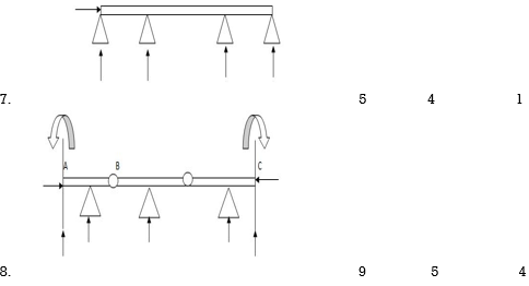
7. External Indeterminacy
When we can't discover assist reactions the use of legal guidelines at statics, it's miles referred to as externally indeterminate structure.
8. Internal Indeterminacy
When we can't discover inner member movements the use of legal guidelines of statics, its miles referred to as internally indeterminate structure.
Boundary condition
Displacement Re stained Displacement allow
Δ x, Δ y, ϴz Nil
Δ y, ϴz, Δ x
Δ x, Δ y, ϴz
Dsi for beams = R – E
Where,
R = No of assist reactions
E = No of Equilibrium equations
Note: For one inner pin, no of extra equations of equilibrium are = m – 1
m = no of individuals linked via way of means of pin.
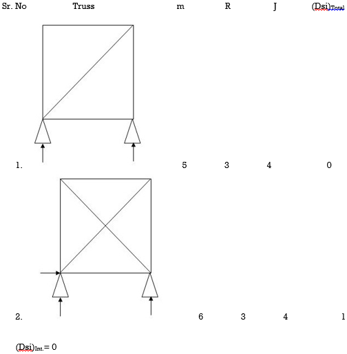
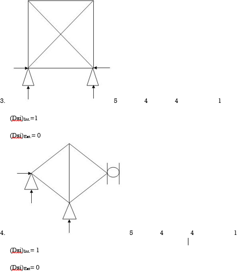
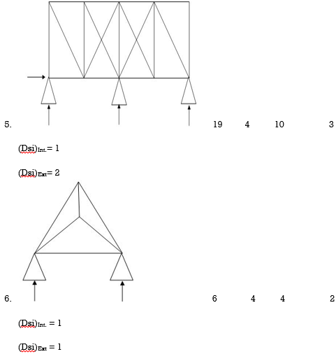
(Dsi)Total = (m + R) – (2J)
Where,
M = No of members
R = No of support reactions
J = No of Joints
(Dsi)External = R – 3
(Dsi)Internal = (Dsi)total – (Dsi)ext
Dsi = (M + R) – 2j
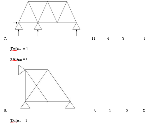
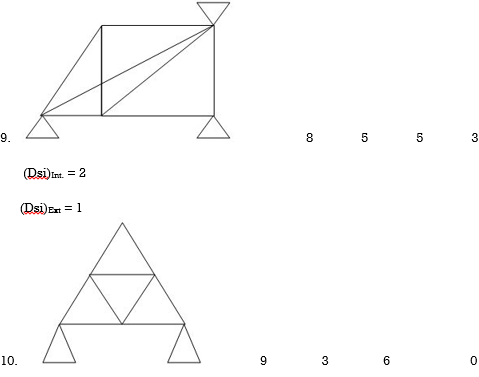
10. Dsi for Frames:
(Dsi)Total = 3m + R – 3J
(Dsi)External = R – 3
(Dsi)Internal = (Dsi)Total – (Dsi)ext
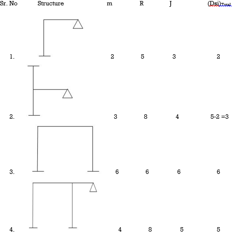
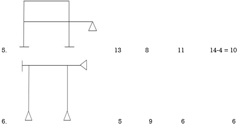
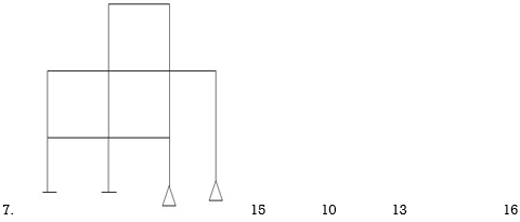
Note:
For Frames:
(Dsi)Ext = R – 3
(Dsi)Int. = 3 {No of closed loops}
(Dsi)Total = (Dsi)Ext + (Dsi)Int.
& for Int. pin Reduced (Dsi) Total by (m-1)
11. Arches:
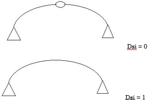
Examples:
1)

R – E = 9-4 = 5
Dsi = 5
2)
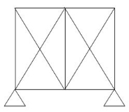
R – E = 5-3
(Dsi)Ext = 2
(Dsi)Int. = 2
(Dsi)Total – (Dsi)Ext = (Dsi)Int.
Dsi = m + R – 2j
= 11 + 5 – 2(6)
= 4
3)
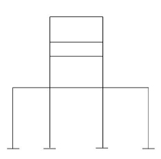
(Dsi)Ext = 9
(Dsi)Int. = 9
R = 12
m = 16
j = 16
(Dsi)T = (3m + R) – 3j - 18
(Dsi)T = (Dsi) + (R - 3)Ext
= 18 – 9
= 92>. Axial deformation of members is neglected.
12. Dki for beams:
 1)
1) ΔXB, ΔYB, ϴB = 2
2)  ϴB = 1
 3)
3)  ΔXB&ϴB = 1
4)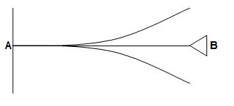 ΔYB&ϴB = 2
5) ϴB, ϴC, ϴD = 3
6)  ϴB, ϴC, ϴDΔYD = 4
7)  = 0
= 0
8)  ϴBA, ϴBC, Δ By = 3
9)  ϴB, Δ By = 2
10) ϴDE, ϴDC, Δ Dy = 6
ϴC, ϴB Δ By
11)  ϴA, ϴB,
ϴD, ϴCB, ϴCD = 10
ΔYC, ϴE
ΔYE, ΔYF1, ϴE
12. Dki for frames:
Frames are of two types
Sway – Horizontal translation of beam in a frame is called as sway.
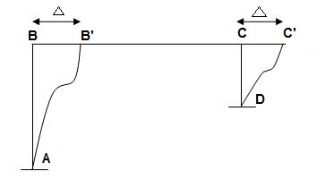
Sway = Δ
13. Application of Force Method to Analysis of Indeterminate Beams:
The flexibility approach is primarily based totally upon the answer of "equilibrium equations and compatibility equations". There will continually be as many compatibility equations as redundant. It is referred to as the flexibility approach due to the fact flexibilities seem within side the equations of compatibility. Another call for the approach is the pressure approach due to the fact forces is the unknown portions in equations of compatibility.
Q= [DQL]+[F][Q]-compatibility equation
DQ=External displacement at redundant position
 Displacement at the redundant position because of applied loading

F=flexibility matrix


It is also called as Force Method
In this method, horizontal displacement is neglected
Degree of indeterminacy=R-E
R=Reaction
E=Equilibrium equation


=4-2
=2
The redundant structure is 2.

1) Use flexibility Matrix Method
Step 1)


=4-2
=2
Redundant structure is 2.

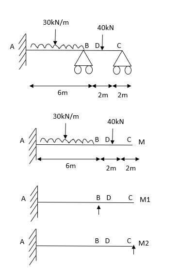
Zone | Limit | Origin | M |
|
|
CD | 0-2 | C | 0 | 0 | x |
DB | 0-2 | D | -40 | 0 | x+2 |
BA | 0-6 | B |
| X | x+4 |


=


 = - 11100 /EI


=333.33/


Key takeaways
1. Find degree of indeterminacy
2. Find reactions (RA, RB, & RC)
3. Flexibility method (Find F11, F12, F21 & F22)
These are methods primarily based totally on linear elastic conduct and conservation of electricity, Energy U = Fx/2 = F2/2k wherein F is the implemented pressure, x is the space moved within side the route of the pressure at its factor of utility and okay is the elastic stiffness of the part, once more within side the route of the pressure at its factor of utility. , i.e. the work done via way of means of outside forces equals the electricity saved within side the structural below
Q.1) EI = 17250 Kn.m2 find strain energy?
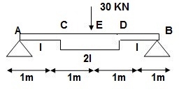
Solution:
∑MA = 0
30 x 2 – RB x 4 = 0
RB = 15
VA = VB = 15 KN
BMC = BMD = 15(1) = 15 KN.M
BMC = 15(2) = 30 KN.M
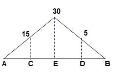
‘M/EI’ Dia.
C.B
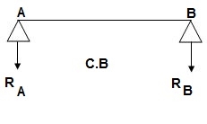
A1 = 1 / 2 x 1 x 15/EI = 7.5/EI
A2 = 2 x 7.5/EI = 15/EI
A3 = 1 /2 x 2 x 7.5/EI = 7.5/EI
A4 = 1 / 2 x 15/EI x 1 = 7.5/EI
Analysis of conjugate beam:
∑MA = -RB(4) + 1/EI{7.5(2/3 x 1) + 15(2) + 7.5(2) + 7.5(3 + 1/31)} = 0
= - RB x 4 + 1/EI[ 5 + 30 + 15 + 25 ] = 0
RB x 4 = 75/17250
RB = 18.75/EI
∑fy = 0
-RA + RB + A1 + A2 + A3 + A4 = 0
RA = 18.75/EI
RA = RB = ½{A1 + A2 + A3 + A4} = 18.75/EI
Slope & Deflection:
(ϴA)R.B = (SFA)C.B = (-)18.75/EI

 = 18.75/EIxC = 1.086 x 10⁻³radxC

 (ϴB)R.B = (SFB)C.B = 18.75/EIxC = 1.086 x 10⁻³ rad xC
(ΔE)R.B = (BME)CB
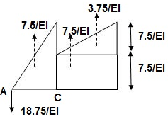
(BME)CB= 1/EI{ -18.75 + 7.5(1 + 1/3 x 1) + 7.5(0.5) + 3.75 (1/3 x 1)}
=1/EI{-22.5}

 ΔE = 22.5/EI xC = 1.304 mm xC
Key take ways
1. Find Reactions
2. M/EI Diagram
3. C.B
4. Analysis of Conjugate Beam
5. Slope and Deflection
The minimal overall capability strength precept is a essential idea used in engineering. It dictates that at low temperatures a shape or frame shall deform or displace to a role that (locally) minimizes the overall capability strength, with the misplaced capability strength being transformed into kinetic strength. His general capability strength is the sum of the elastic stress strength, U, saved within side the deformed frame and the capability strength, V, related to the implemented forces
Π = U + V (1)
This strength is at a desk bound function whilst an infinitesimal version from such function entails no alternate in strength
δ Π = δ ( U + V ) = 0 (2)
The precept of minimal general capability strength can be derived as a unique case of the digital work precept for elastic structures issue to conservative forces.
The equality among outside and inner digital work (because of digital displacements) is:
∫ S t δ u T T d S + ∫ V δ u T f d V = ∫ V δ ϵ T σ d V (3)
In the unique case of elastic bodies, the right-hand-aspect of (3) may be taken to be the alternate, of elastic stress strength U because of infinitesimal versions of actual displacements. In addition, whilst the outside forces are conservative forces, the left-hand-aspect of (3) may be visible because the alternate within side the capability strength function V of the forces. The function V is described as
V = − ∫ S t u T T d S − ∫ V u T f d V
Where in: the minus signal implies a lack of capability strength because the force is displaced in its direction. With those subsidiary conditions, (3) becomes:
− δ V = δ U
This leads to (2) as desired. The variation shape of (2) is frequently used as the idea for growing the finite detail approach in structural mechanics.
Virtual work is the work done with the aid of using a actual pressure appearing via a digital displacement or a digital pressure appearing via a actual displacement. The Unit Load Method When the precept of digital work is used to calculate the displacement, at a co-ordinate, the device of outside forces,̄ F"> is selected for you to consist best of a unmarried unit pressure at coordinate. A digital displacement is any displacement constant with the restrictions of the shape, i.e., that fulfill the boundary situations on he supports. A digital pressure is any device of forces in equilibrium. f(x) and y(x) are actual forces and related displacements. ̄y(x) is a digital displacement constant with the boundary situations.
1. Castiglione’s 1st theorem:
It states that displacement at a point of application of load in the direction of load is equal to partial derivative of strain energy of structure with respect to load.
1]. ӘU/ӘQi = Δj
U = strain energy
Qj = Force in the direction j
Δj = Displacement in the direction j
2]. Strain energy: UAxial force = ∫L0P2dx/2EA
UB.M = ∫L0M2dx/2EI
UTorsion = ∫L0T2dx/2GJ
Deflection = translation
3]. Procedure of displacement analysis by Castiglione’s theorem:
Step 1:
Apply imaginary load ‘Q’ at section where displacement is required.
Note:
1. For horizontal translation apply ‘Q’ in horizontal direction For vertical translation apply force Q in vertical direction
2. For finding ‘slope’ (rotation) apply couple Q.
Step 2: Find support reactions and draw member F.B.D’s
Step 3: Prepare table:
Zone origin limits EI M ӘM/ӘQ
Step 4: Find displacement using Δj = ∫L0M/EI {ӘM/ӘQj} dx
Find ΔB:

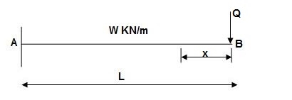
Zone Origin Limits EI M ӘM/ӘQ
BA B 0 to L EI –Q(x) – W(x2/2)-x
ΔB = ∫L0 M/EI (ӘM/ӘQ) dx = ∫L0 {-W(x2/2)}(-x) dx
= W/2EI{x4/4}L0
 ΔB = WL4/8EI ( )
Find
1]. Vertical deflection at ‘c’,
EI = constant
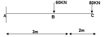
M Diagram
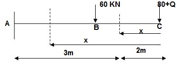
From above Fig:
Table
Zone Origin limits EI M ӘM/ӘQj
CB C 0-2 EI -(80 + Q)x - x
BA C 2-5 EI -(80 + Q)x - x-60(x-2)
ΔC = ∫20-(80) x/EI {-x} dx + ∫52 {80x – 60(x-2) (-x) dx/EI}
= ∫2080x2/EI dx + ∫52 {80x2 – 60x2 + 2x}dx/EI
= 1/EI {213.33 + 4200}
 ΔC = 4413.33/EI ( )
2]. Find vertical deflection at point C
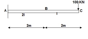
M Diagram
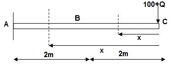
Zone Origin Limit EI M ӘM/ӘQ
CB C 0 – 2 EI - (100 + Q)x -x
BA C 2 – 4 EI -(100 + Q)x -x
ΔC = ∫20 – 100x/EI (-x) dx + ∫42 -100x/EI (-x)dx
= ∫20100x2/EI dx + ∫42100x2/2EIdx
= 266.66 + 1866.6/2 = 266.66 + 933.33
For cantilever always write load from free end. For simply write load from supports.
ΔC = 1200/EI
3]. Find slope at ‘A’, deflection at ‘C’.
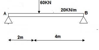
M Diagram
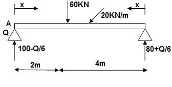
Reactions in M dia.
∑MA = VB (6) – 20 x 6 x 3 – 60(2) – Q = 0
VB = 80 + Q/6
∑F y = VA + VB – 60 – 20 x 6 = 0
VA = 100 – Q/6
Zone Origin limits EI M ӘM/ӘQ
AC A 0 – 2 EI (100-Q/6)(x) 1 – x/6 + Q – 20(x2/2)
BC B 0 – 4 EI (80+Q/6) (x)-20x2/2 x/6
ϴA = ∫20 {100(x) – 10x2} {1-x/6} dx/d EI + ∫40{80x – 10x2}x/6dx/EI
= 1/EI {135.55 + 177.78}
 ϴA = 313.32/EI ( )
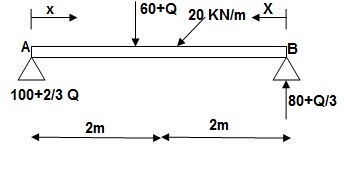
∑MA = VB (6) – 20(6)(3) – (60 + Q)2 = 0
VB = 80 + Q/3
∑F y = VA + VB – (60 + Q) – 20(6) = 0
VA = -80 – Q/3 + 60 + Q + 120 = 0
VA = 100 + 2/3Q
4]. Find a deflection at a point C

i) M Diagram
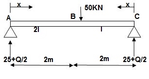
Zone Origin Limit EI M ӘM/ӘQ
AC A 0 – 2 EI (25 + Q/2)x x/2
BC B 0 – 2 EI (25 + Q/2)x x/2
ΔC = ∫20(25x)x/2dx/EI + ∫2025x(x/2)dx/2EI
= 33.33 + 16.66/EI
 ΔC = 50/EI ( )
2. Slope & Deflection of Beams and frames by Castiglione’s 1st theorem:
1]. Find deflection at D
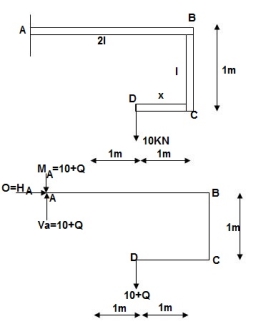
∑MA = MA – (10+Q)(1) = 0
MA = 10 + Q
∑F y = VA – (10 + Q) = 0 VA = 10 + Q
∑F x = HA = 0
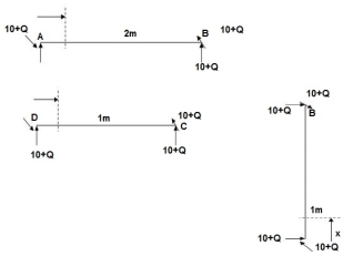
Zone origin limits EI M ӘM/ӘQ
AB A 0 – 2 2EI (10+Q) x-(10+Q) x-1
CB C 0 – 1 EI - (10 + Q) -1
DC D 0 – 1 EI - (10 + Q) x - x
Δ D y = ∫20 (10x - 10)(x-1)dx/2EI + ∫10 -10(-1)dx/EI + ∫10 -10x(-x)dx/EI
= 3.33 + 10 + 3.33/EI
 Δ D y = 16.66/EI ( )
3. Castiglione’s second theorem
Basics (1)
i) Beam fixed at both end is called as Fixed beam
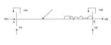
ii) Fixed beam is statically indeterminate
Number of unknown Reactions = R=6
Number of Equilibrium equation = E=3
Dsi – R-E = 6-3 =3
Note:
For beam subjected to vertical loads lonely-horizontal reactions are zero.
For Fixed beam subjected to vertical loads only.
Number of unknown reactions = R=4
Number of equilibrium equation = E=2
Dsi – R-E = 4-2 =2

For vertically downward load fixed and moments are begging in nature.


4) Advantages of fixed beam
5) For fixed beam,
Tangents drawn at both ends are horizontal therefore angle betn tangents is equal to area of  Diagram is equal to zero.

1= Area  ‘Dia’ =0
Position of B with respect to tangent drawn at A
BA = Area  Dia
Dia =0
=0
Key takeaways
1. ӘU/ӘQi = Δj
2. Strain energy: UAxial force = ∫L0P2dx/2EA
3. Procedure of displacement analysis by Castiglione’s theorem
Step1: Apply imaginary load ‘Q’ at section where displacement is required.
Step2: Find support reactions and draw member F.B.D’s
Step 3: Prepare table:
Zone origin limits EI M ӘM/ӘQ
Step 4: Find displacement using Δj = ∫L0M/EI {ӘM/ӘQj} dx
Reciprocal theorem is Maxwell reciprocal theorem. Reciprocal theorem is one of the simple ideas of structural analysis. Reciprocal theorem may be used to lessen the wide variety of aspect calculate in given shape. Maxwell reciprocal theorem is likewise referred to as Maxwell reciprocal rule. Reciprocal theorem is a courting are similarly separate distortions in an elastic shape under load. Reciprocal theorem is likewise used to test the calculation has correctly anticipated are similarly of separate distortions. Maxwell Theorem of Reciprocal Deflections This theorem states that, Deflection at A because of a unit load carried out at B = Deflection at B because of a unit load carried out at A
Unit Load Method is also named as virtual (digital) work approach. Digital work is a process for computing a single factor of deflection at any factor on a shape. The approach lets in the fashion dressmaker to consist of in deflection computations the influence of assist settlements, temperature change, and fabrication errors. These different outcomes consist of the actual loads, temperature change, assist agreement and so forth. In different words, the deflected form because of the actual forces is thought to be the digital deflected form of the dummy shape, and the precept of labor and power is applied
The Unit Load Method When the precept of digital work is used to calculate the displacement at a coordinate, the gadget of outside forces, is selected in order to consist simplest of an unmarried unit pressure at coordinate Unit Load Method for Deflection Calculation
The unit load approach is also known as the approach of digital work. The primary equation to calculate displacement (whether or not translational or rotational) at a given factor of a beam or body is given as,
A = f M m dx A = f El
Where, M Moment at any factor in a shape because of implemented hundreds m Moment at any factor in a shape because of the unit load (pressure or second) at the focal point similar to the parameter of interest (deflection or rotation) E Modulus of elasticity I Moment of inertia of the go phase of a member To compute a factor of deflection with the aid of using the approach of digital work, the fashion dressmaker applies a unit pressure to the shape on the factor and within side the path of the desired displacement. This pressure is frequently referred to as a dummy load the displacement it will go through is produced with the aid of using different outcomes.
1. Influence line:
An influence line for a given characteristic, which includes a reaction, axial pressure, shear pressure, or bending moment, is a graph that indicates the version of that characteristic at any given factor on a shape because of the software of a unit load at any factor on the shape. Influence line is additive and scalar. The scaled most and minimal are the essential magnitudes that need to be designed for within side the beam or truss.
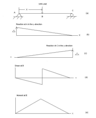
Examples:
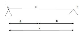
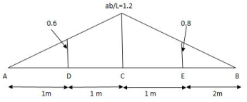
1] A simply supported beam is subjected to loads as shown in fig.
Using influence lines find
i) support reactions
ii) shear force & bending moment at ‘C’
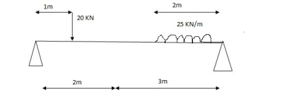
Solution:
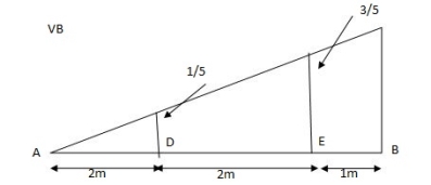
1) VA& VB
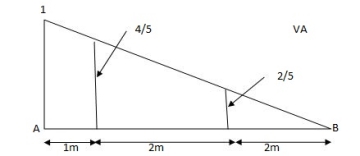
VA = 20 + 25 1
 = 16 + 10 = 26 KN
VB = 20  + 25
+ 25  +
+  = 4 + 40 = 44 KN

 =
=  =0.6
=0.6
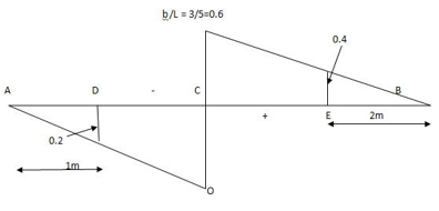
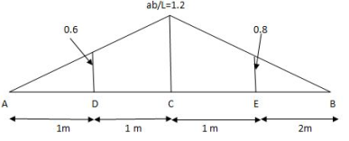
SF@ c = 20 (-0.2) + 25= 5KN
BM@ c = 20 (0.6) +  (2 0.8) (25)
= 32 KN. M
2. Rolling loads:
Loads which roll over the given structural detail from one quit to the every other quit. In a rolling load most shears force, bending moments.
Example: train on the railway track, automobiles at the bridges or roads are rolling loads etc.
Rolling loads there are 3 types:
Uniformly distributed load there are main types: 1) Longer than span 2) Smaller than span
ILD for beams and rolling load:
It is a diagram which shows version of AF, SF and BM on the sort of characteristic at a unique section for numerous function of moving load.
It is a diagram which indicates variation of AF, SF and BM on any such function at a particular section for various position of moving load.
AFD, SFD, BMD ILD
Load position fixed (for particular %)
How to find value of function from ILD
i) Structure subjected to point loads

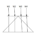
Meg. of function = W1Y1 +W2Y2 +W3Y3+W4Y4
ii) Structure subjected to udl
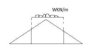
Magnitude of function = {Area of ILD under UDL} 𝓌
1) i)VA =? (ii) MA=? (iii) SF = (iv) BM =
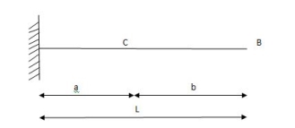
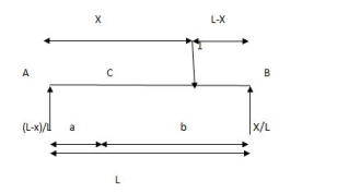
1) ILD’s for VA & MA
Consider unit load at a distance
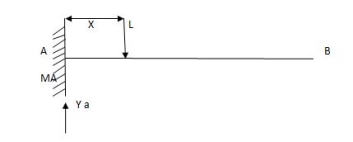
MA = MA -1 (x) =0
MA =x
X VA MA
0 1 0
L 1 0
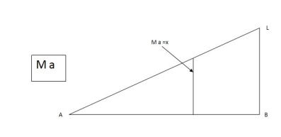
ILD for bending moment at A is as below
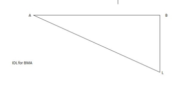
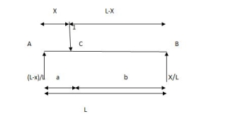
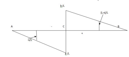
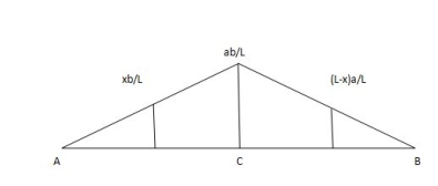
ILD for shear force & BM at ‘C’

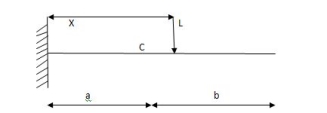
SF@ c =0, BMC =0
SFC =1; BMC = -1 (x-a)
For x = a; BM@ c =0 X = L;
BMC = -1(1-a) c b
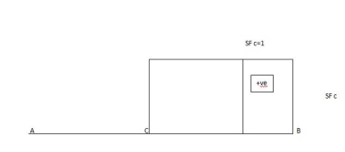
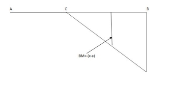
2)
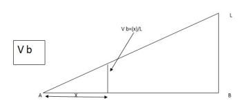
1) ILD’s for VA& VB
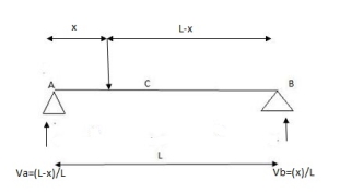
x VA VB
0 1 0
L 0 1
2) SF c & BM c
1)
2)
Example:
1] A simply supported beam subjected to moving udl
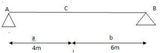
Solution:
1)
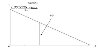
VA max =  (20) = 75 KN
VA max =  20 = 75 KN
Note:-
Absolute maximum shear force is nothing but greater 07 VA, max & VB, max
Abs. max SF = 75 KN
2)
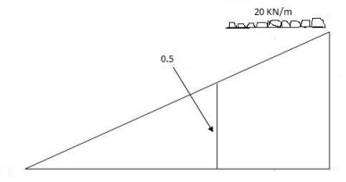
max.(–ve) SFc = (-)  (20)
(20)
= ( ) 16KN
Max. +ve SF c = 
=35KN
Max .SFc = 35 KN
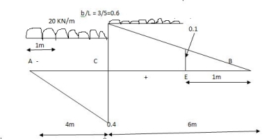
Note:
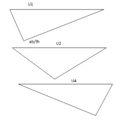
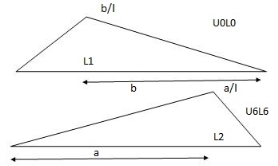
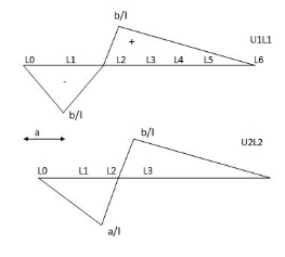
When length of udl is smaller than bas of triangle, placed udl such that load per a on LH & RHS of height of triangle is same.
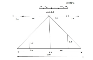
 =
= 
x = 2m
 =
=  (5) (20) =180 KNm
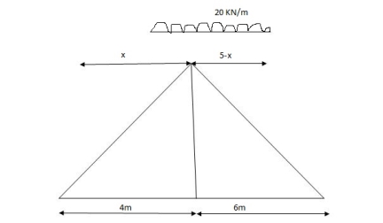
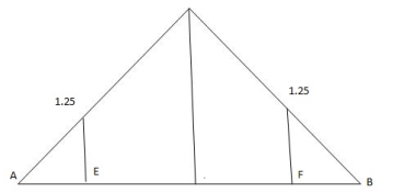
Abs. max BM =  (5) (20) =187.5 KNm
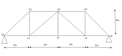
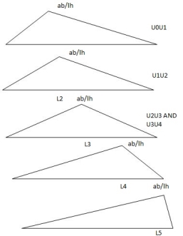
Diagonal members design
Top camp
Key takeaways
1. Find VA VB
2. Find SF
2. Find BM
3. Draw influence line
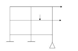
2. Braced frame structure
Rigid jointed plane Frames
e. Semicircular hinged arch

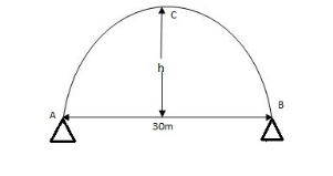
Circular Eqn
IMP
At diffn level
 =
= 
Parabolic Eqn for half portion
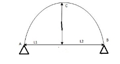
Y =  (2l1 -x)
Y =  (2l2 -x)
2. At same level Parabolic arch
1. Draw FBD
2. Find Real due to Equilibrium condition =0, efs = 0cm,
3. Consider half part of Arch (i.e. left/Right) find Horizontal thrust.
4. Find B.M. consider parabolic can find vertical dossy
5. Find normal thrust I Radial shear.
3. At different level parabolic arch
1. Find length  =
=  , efy = 0
2. Consider half portion I take moment at c you will get VA& VB
3. Equating with Efy = 0 get H
4. Find normal thrust Radial Shear
4. Hinged parabolic Arch at some level
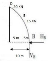
Example: A 3 hinged arch has a span of 30 cm & arise of 10m the arch carries of UDL 6 KN/M on the left half of the span it also carries two concentrated load of 16 KN I 20 KN at 5m I 10m from the right end determine an at support. B.M. at 10m from right I radial shear & normal trust at c from left end.
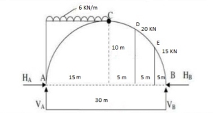
Step1. Draw FDB
Step2. Find resultant by equilibrium can
EMA = 0
6 x 15 x 7.5 – 20 x 20 – 16 x 25 + VB x 30 = 0
VB= 49.17kn
EFY = 0
VA + VB = 6 x 15 + 20 + 16
VA = 76.83 KN
EFx= 0
HA – HB = 0
HA = HB
Step3. Cut the arch from CPI
Consider left part of Arch AC
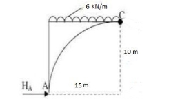
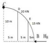
VA= 76.83 EMC = 0
EMC = 0 - 20 V 5 – 16 x 10 – H5 x 10
- 76. 83 x 15 + HA x 10 + 6 x 15 x 7.5 = 0
- HA = 47.75Kn HB = 47.75Kn
Consider any part you will get some on
RA= RB =
RB = 
Step 4 = Find BM at 10m from right end
20kn x = 10 m y =?
EMD yd = 4
- 16x5 – HB x YDv
+ VB x 10olD =
- 16 X 5 -47.75 X 8.8+ 49.17 X 10
MD = - 8.5KNM
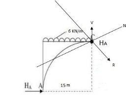
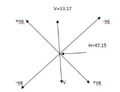
N = + HCOSO – Csinq
R = Hsinq + VcosQ
Q) Find by parabolic eq.n
l = 30, x = 15m
y = 
y = 
Differentiate

Tan =
= 
 = 0
= 0
N = 47.75 cos - 13.17 sino
N = 47.75 KN
R = 47.75 sino + 13.17 coso
R = 13.17kn
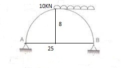
Example: A parabolic 3 hinged arch curries 4UDl 30kn/m on the left of the span it has a span of 16m. Iacenthaleire 3m. Determine the resultant ref 6 supports find the D. m. normal trust I redial should udl xx 2m from left sun
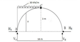
EmA= 0
VB X 16 – 30 X 8 X 4 = 0
VB = 60 KN
VA = 180 KN
EMc = 0
- VA X 8 + 4 X 3 + 30 X 8 X 4 = 0
H = 160 KN
HA = HB = 160 KN
RA = 
RB= 
B. m. at x = 2 m from A
By using parabolic Arch
Y = 
X = 2m
L = eise – 3m
L = 16
Y = 
Y = 1.3125
Mx =Yax 2 ++4 AXY + 30 x 2 x 1 =
- 18ax2 + 160 x 1.31 2 x 1
Mx = 90.4knm
Radial sheat
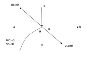
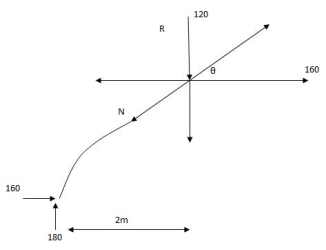
Na = Hcos+ usin
Rx = Ucos - HsinQ
 =
= 
 = tan =
= tan 
= 29˚21’
Rx = 12.cos 29l I – 160sin 29.21
Rx = 26.1 J KN
N = 160cos29.21˚+ 120sin29.21’
N = 198.28kn
Key take ways
At same level Parabolic arch
1. Draw FBD
2. Find Real due to Equilibrium condition =0, efs = 0cm,
3. Consider half part of Arch (i.e. left/Right) find Horizontal thrust.
4. Find B.M. consider parabolic can find vertical dossy.
5. Find normal thrust I Radial shear.
At different level parabolic arch
1. Find length  =
=  , efy = 0
2. Consider half portion I take moment at c you will get VA& VB
3. Equating with E f y = 0 get H
4. Find normal thrust Radial Shear
Influence liens for simply supported beam

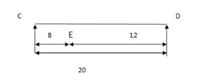
Find reactions at support, S.F.& B.M. at a section _______ at A RA=?
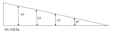
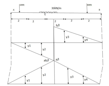
10 y1 +  2 30 + 60 y4
 =
=  y1 =0.8
  =
=  y3=0.4
 =
=  y2 =0.6
  =
=  y4=0.2
RA = 10 0.8 +  2 30 + 60 0.2
RA = 50 KN
RB= 10 y1 +  30 2 + 60 y4
 =
=  y1 =0.2
  =
=  y3=0.6
 =
=  y2 =0.4
  =
=  y4=0.8
RB = 10 0.2 +  2 30 + 60 0.2
RA = 62 KN
Near for at E
 =
=  = 0.5
= 0.5  =
=  y3
y3
 =
=  = 0.5
= 0.5  =
=  y4
y4
 =
=  y2
y2  =
=  y1
y1
at E = 10 y1 +30 1 + 30 1
  + 60 y4
at E = 8 KN
 -ve S.F.at E = 10 -y1 + 30 1
 =
=  =
=  =2.5
=2.5
 =
=
 =
= =
=
 =
= y2
y2 =
=
B.M. at E = 10 y1 + 30 1  +30 1 + 60 y4
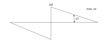
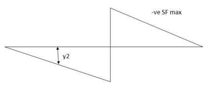
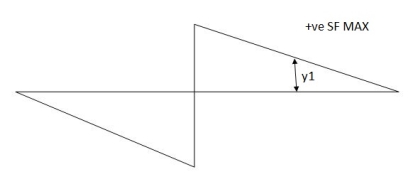
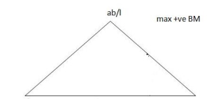
Find the position of loads to get max-ve S.F. of B.M.
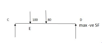
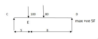
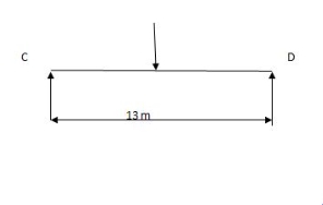
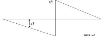
Two wheel loads of 80 KN & 100 KN at 3 m find max.m the S.F. & maxm -ve S.F. and B.M. at 5 m from left

Key takeaways
1. Find reactions at support, S.F. & B.M. at a section
2. Find the position of loads to get max -ve S.F. of B.M.
3. Draw SFD & BMD
Application of Determinate and Indeterminate Structure:
A simply supported beam is subjected to loads as shown in fig.
Using influence lines find
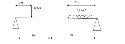
1) VA& VB
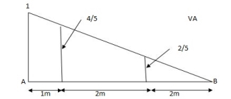
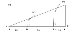
VA = 20 + 25 1
 = 16 + 10 = 26 KN
VB = 20  + 25
+ 25  +
+  = 4 + 40 = 44 KN


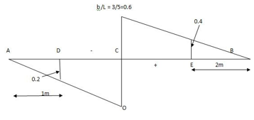
SFc = 20 (-0.2) + 25= 5KN
BMc = 20 (0.6) +  (2 0.8) (25)
= 32 KN/M
References:
1. Mechanics of Structures Vol. II by S B Junnarkar and Dr. H J Shah, Twenty second
edition, Charotar Publishing House Pvt. Ltd.
2. Basic Structural Analysis by C. S. Reddy, Second Edition, Tata Mc Graw Hill.
3. Structural Analysis by R. C. Hibbler, sixth edition, Pearson Education.
4. Plastic Methods of Structural Analysis by B. G. Neal, Champman and Hall.
5. Elementary Structural Analysis by Senoltku, Charles Head Norris, John Benson
Wilbur, TMH.
6. Intermediate Structural Analysis by C K Wang, Tata McGraw Hill.


