Unit-2
Analysis of Beams and Frames
Analysis of beam and rectangular portal frames with indeterminacy up to second degrees
Case I):
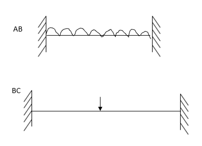
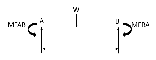
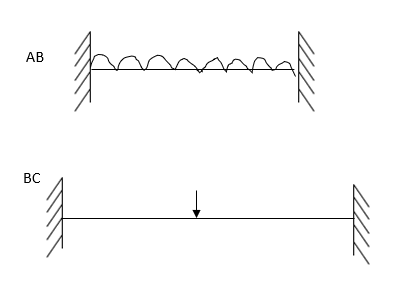
1. Fixed beam carrying udl throughout:

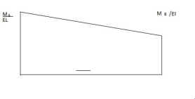
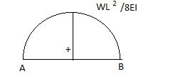
Area & (A ) @B
) @B
For fig (i) ……………..
(-)  (L) …………..(i)
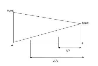
(A ) @B =
= (-)  +
+ 
= (-) ……………. (II)
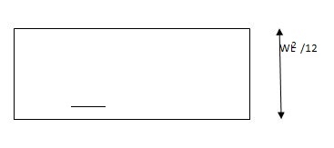
Fig (2)
A =  (L)
(L)  =
= 
A B =
B = =
= 
As per principle (1)
Total area =0
 +
+  =0
=0
 =
=  ……….(I)
As per principle (2)
 @B =0
@B =0
 +
+  =0
=0
( ……………. (2)
From (1),
MB =  = MA put in (2)
2MA +  MA +
MA + 
MA =
MA = 
MB = 
2. Fixed beam carrying udl end moments are 

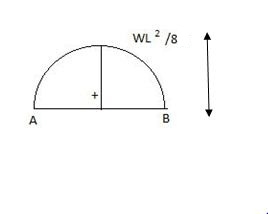
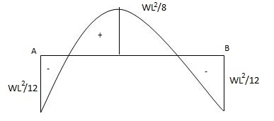
Case (II):
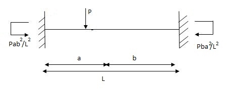
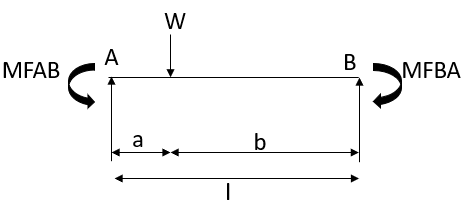
Fixed beam with point load.
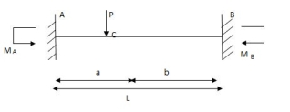
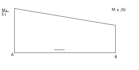
Area & @B for free BMD
A =  (L)
(L) 
A =
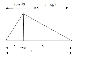
 @B =
@B = 
= 
As per principle (1)
Total Area =0
 (L) +
(L) +  =0
=0
MA + MB =  ……….. (1)
As per principle (2)
 @B = 0
(-)  (2MA+2MB) +
 =0
=0
2MA+2MB = (L + b) ………… (2)
From (1)
MB =  MA (Put in eqnc2)
2MA +  (L +b)
MA =
= 
MA =
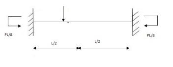
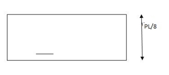
Special cases

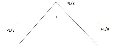
Case (III)
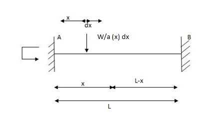
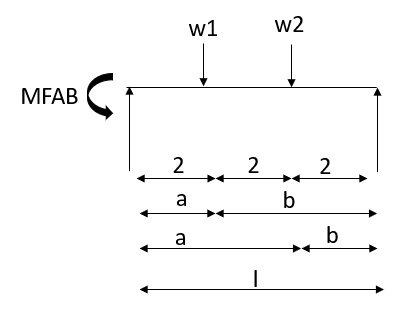
Fixed beam carrying partial udl
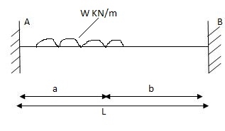
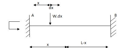
= 
MA = 
MB = 
= 
= 
=
=
MB= 
Special case:

MA = 
= 
MB = 
= 

MB = 
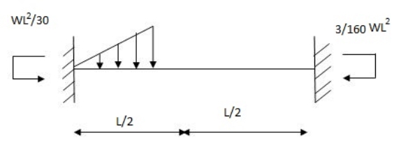
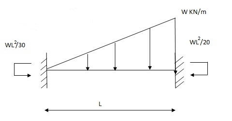
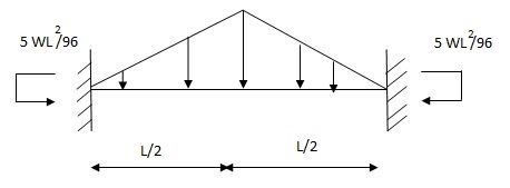
Case (IV)
Fixed beam with partial uvl
Diagram:
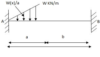
MB = 
= w - 
Case (V)
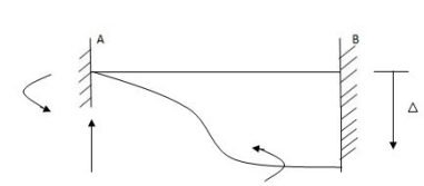
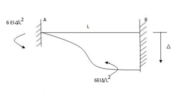
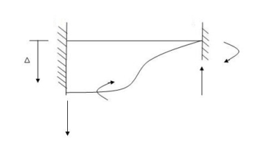
Fixed beam with sinking of support (A)
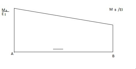
As per principle (1)

 Area of M dia. = 0
EI

 (-) MA + MB (L) = 0
2 EI
MA + MB = 0
MA = - MB (1)
As per principle (2)
 (AX) @ B =0

 tBA = (AX) @ B =
 (-) L2 (2MA + MB) = (-)
6EI
3M – LM2 = ………..From (1)
Final Fig.
Case (VI)
Fixed beam with rotational fielding
Diagram
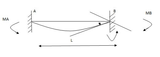
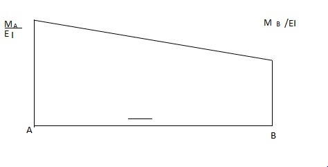
 i) Area M dia. = B
EI

(-1) 1 MA + MB (L) = B

 EI 2
EI 2

 MA + MB= (-) 2EI (B) (1)
L


 Area M xXB = tBA = 0
EI

 (-) L2 2MA + MB = 0
6EI
 2MA + MB = 0 (2)
From (1)
…………..
2MA = 2EI (B) - MA = 0
 L
L
MA = 2EI (B)
 L
L
MB = 4 EI (B)
 L
L
For rotation B anticlockwise
Diagram

(Both end moment & rotation clockwise)
Fixed beam with couple
Diagram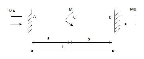
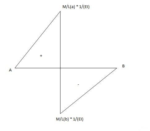
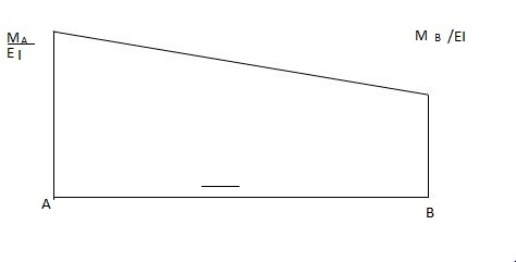
Area & (AX) (a) B

 A1 = 1 mA + mB (L)
 EI 2
EI 2

A2 = 1 1 x ax m (a)


 EI 2 L
= ma2
 2LEI
2LEI

A3 =  x b x
x b x (b)
(b)
= - mb2
 2 LEI
2 LEI


 (A x) 1 (a) B = (-) L2 2mA + mB
6 EI


 (A x) 2 (a) B = (-) Ma2 b + 1 a
2 LEI 3

 (A x) 3 (a) B = (-) Mb2 2 b

 2 LEI 3
= (-) Mb3
 3 LEI
3 LEI
As per principle (1)
Total Area = 0
∑ A = 0

 (-) mA + mB (L) + ma2 - mb2 - 0

 2 2L 2L

 mA + mB (L) = m (a2 – b2)
2 2L
 mA+ mB = m (a-b) (1)
 L
L
(3) (Ax) (a) B = 0
 (-) L2 (2 mA + mB) + ma2 b + a - mb3 = 0


 6 2L 3 3L

 2MA + MB= 6 (m) a2b+a - b3


 L2 2L 3 3L
 2MA + MB = M 3a2b + a3 – 2b3

 L (2)
L (2)
From (1),
MB= M (a-b) - MA put in (2)
 L
L


 2MA + M (a-b) – MA = M 3a2b + a3 – 2b3
L L3


 MA = M 3a2b + a3 – 2b3 - M (a-b)
L3 L
 Multiply ÷ by ………….
 MA = M 3a2b + a3 – 2b3 -(a-b) ( ………..)
L3

 MA = M 3a2b + a3 – 2b3 -(a-b) ( ………..)
L3

= M 2a2b – b3 – ab2
 L3
L3
MA = MB (a – o) (………….)
 L3
L3
 MA = MB (2 a-b)
L3

 MB = M (a-b) - MB (2a-b)
L L2
MB = (-) MQ (2b – a)
 L2
L2
Note:
(Free end moment)
Show FEM in the direction of couple applied and after substituting a & b if answer is respective arrow shall be corrected sign changes.
Special case:
Couple at centre
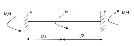
B = 10mm (1)
E = 200 G pa
I = 8 x 106 mm4
EI = 1600 KN/M2
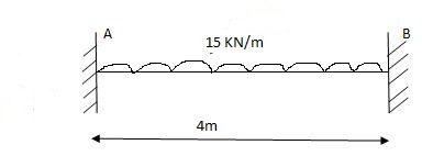
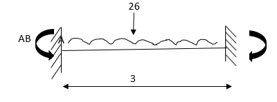
(1) FEM

MA1 = (-) MB1 = WL2 = 15 X 16 = 20 KNM

 12 12
12 12
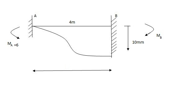
MA = MB
Final MA =?
MB =?
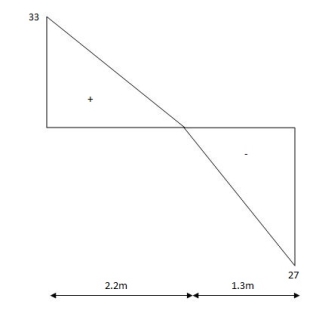
MA = VB (4) – 1
VA = 27
∑Fy = 0
VA /VA =
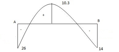
BMP
BMA= (-) 26 KNM
BMB = (-)19 KNM
 BMC = 33 (2.2) – 26 – 15 (2.2)2
 Z
Z
BMC = 10.3 KNM
BMP
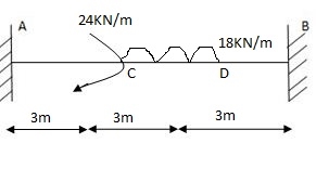
(1) FEM’S
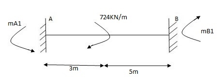
MA1= (-) Mb (2a-b)
 L2
L2
= (-) 24 x 5 (1)
 (8)2
(8)2
= (-) (1.875) KNM
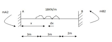
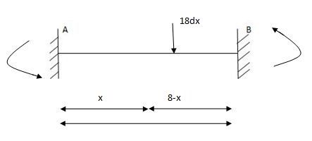
MA1 = 
=
MA2= 
MA2= 
MA2 = 44.92 KNM
MB2 = (-) 56.320 KNM
MA = MA1 + MA2
= 1.875 + 44.92
MA = 43.045 KNM
MB = - 7.875 – 56.32 = - 64.195 KNM
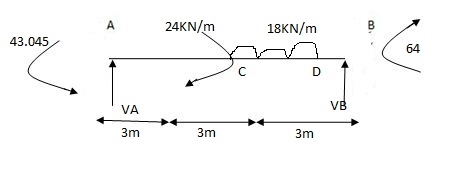
 X1 = y1 (a)
 y1 + y2
∑F y =VA + VB – 18 3 =0
 VA =17.98 x 18KN
VA = 18KN
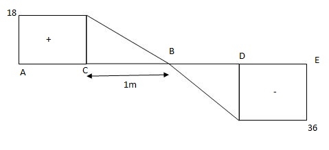
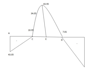
BMD
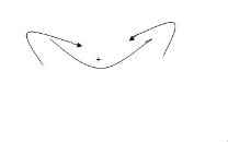
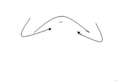
BMA = - 43.05 KNM
BMB = - 64.19 KNM
BMC(R) = 18 (3) – 43.05 = 10.95 KNM
BMC(R) = 10.95 + 24 = 34.95 KNM
BMF = 18 (4) – 43.05 + 24 - 18 = 43.95 KNM
 2
2
1. Principle (I):
Angle between tangents drawn to elastic curve at any two points A & B is equal to area of M/EI diagram between A & B
2. Principle II:
Position of B on elastic curve with respect to tangent drawn at A is equal to moment of area of M/EI diagram between A & B about B.
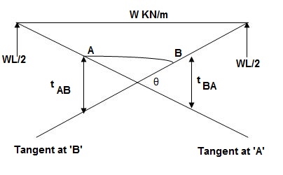
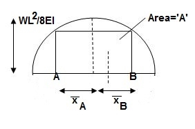
As per principle 1:ϴ = Area (A)
 Principle 2: t BA = (A) (xB)
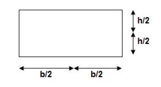
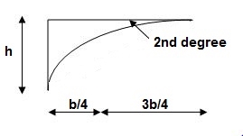
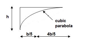
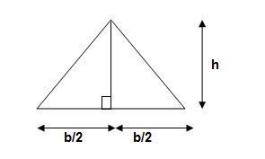
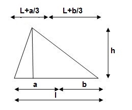
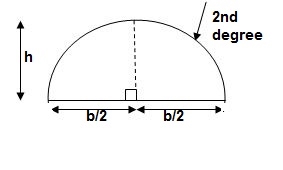
3. Area and CG
For rectangle
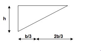
For parabola (udl)
For cubic parabola (UVL Load)
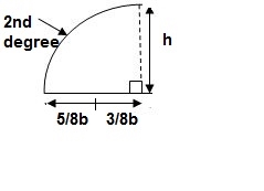
4. Steps for Analysis Moment Area method:


Example:1]
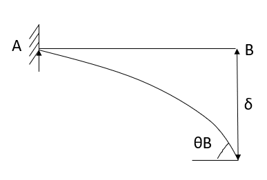
Derive slope & Deflection at free end of cantilever
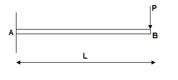
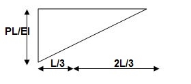
Solution:
ϴB = Area of (M/EL) AB
= ½ x L (PL/EI)
 ϴB = PL2/ZEI ( )
t BA = ΔB = (Area)AB x xB
= (PL2/2EI) (2/3L)
 ΔB = PL3/3EI ( )
Example: 2]
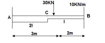
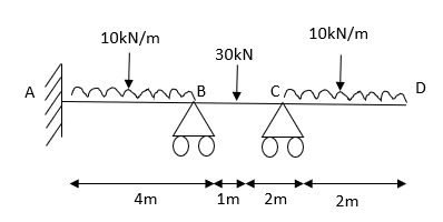
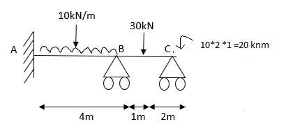
Find: ϴC, ΔC?
Solution:
BMD:
BM at c = 0
BMB = (-) 10 x 2 x 1
= (-) 20 KNM
BMA = (-) 30 x 3 – 10 x 2(4)
= (-) 170 KNM
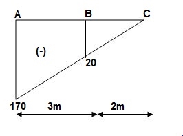
A1 = 30/EI
A2 = ½ x 75/EI x 3 = 112.5/EI
A3 = 1/3 x 2 x 20 x 20/EI = 13.33/EI
Elastic curve
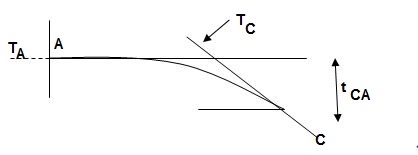
Slope & Deflection:
ϴC = Area of (M/EI) dia. |CA
ϴC = A1 + A2 + A3 = 1/EI {30 + 112.5 +13.33}
 ϴC = 155.83/EI ( )
ΔC = t CA = (A1x1 + A2x2 + A3x3) C
= 1/EI (30 x (3.5) + 112.5(2 + 2/3 x 3) + 13.33 (3/4 x 2))
 ΔC = 575/EI ( )
Example: 3]
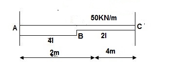
Find: ϴC&ΔC
Solution:
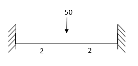
E = 2 x 10⁵ M Pa
I = 250 x 3503/12
EI = 1.78 x 10⁵ KNm2
BMA = -50 x 4 x (2 + 2)
= - 800 KNM
BMB = -50 x 4 x 2
= -400 KNM
BMC = 0
BMD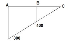
M/EI Dia.:
A1 = 100 x 2/EI = 200/EI
A2 = 1/ 2x 100/EI x 2 = 100/EI
A3 = 1/3 x 200/EI x 4 = 266.67/EI
Elastic curve
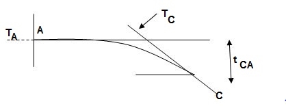
ϴC = Area of (M/EI) AC
= A1 + A2 + A3
= 200 + 100 + 266.67/EI
= 566.67/EI
 ϴC = 3.17 x 10⁻³ rad. ( )
 ΔC = t CA = {Area}A-C x xC
= (A1x1 + A2x2 + A3x3)@C
= 200/EI x (4+1) + 100/EI x (4 + 2/3 x 2) + 266.67/EI(3/4 x 4)
= 1000/EI + 533.33/EI + 800.01/EI
= 2333.34/EI
= 13.1 x 10⁻³ m
 ΔC = 13.1 mm ( )
Example: 4]
Find ϴC&ΔC
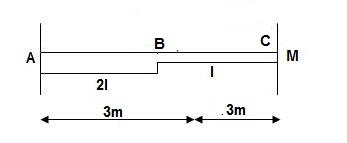
Solution:
BMD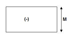
A1 = M/2EI x 3 = 1.5M/EI
A2 = M/EI x 3 = 3M/EI
ϴC = Area (M/EI) A-C
=A1 + A2
ϴC = 4.5M/EI
ΔC = t CA= (A1x1 + A2x2)@c
= 1.5M/EI x (3+1.5) + 3M/EI (1.5)
 ΔC = 11.25M/EI ( )
Example: 5]
Find: ΔC
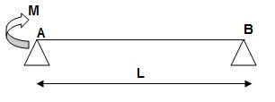
Solution:
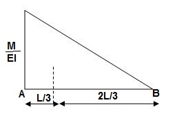
BMA = M
BMB = 0
BMD/‘M/EI Dia.
Elastic Curve
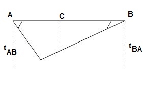
Slope & Deflection
 t AB = {Area}A-B x(xA)
= 1 / 2 x M/EI x L {1/3L}
t AB = ML2/6EI
 t BA = {Area}A-B x(xB)
= 1 / 2 x M/EI x L {2/3 L}
t BA = ML2/3EI
 ϴA ≈ tan (ϴA) = t BA/L = ML/3EI ( )
 ϴB ≈ tan (ϴB) = t AB/L = ML/6EI ( )
t AB/L = C1C3/L/2
C1C3 = t AB/2 = ML2/12EI
 t CB = Area C-B x (xc)
= 1 / 2 x M/2EI x L/2 x {1/3 x L/2}
t CB = ML2/48EI
ΔC = C1– C2
= C1C3 – C2C3
= ML2/12EI – ML2/48EI
 ΔC = ML2/16EI ( )
Example:6]
Find: ϴC, ΔC=?
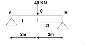
Solution:
BMA = BMB = 0
BMC = PL/4
= 40 x 4/4
= 40 KNM
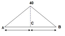
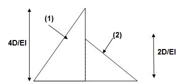
A1 = 1 / 2 x 2 x 40/EI = 40/EI
A2 = 1 / 2 x 2 x 20/EI = 20/EI
Elastic curve
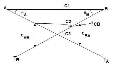
Slope & Deflection
 t AB = (Area)A-B x xA
(A1x1 + A2x2)@A
= 40/EI x (2/3 x 2) + 20/EI (2 + 1/3(2))
= 53.33/EI + 53.33/EI
t AB = 106.67/EI
 t BA = {Area}AB x xB
= (A1x1 + A2x2)@B
= 1/EI {40 x (2 + 1/32) + 20(2/3 x 2)}
= 133.33/EI
 ϴA ≈ tan (ϴA) = t BA/L = 133.33/4EI = 33.33/EI ( )
 ϴB ≈ tan (ϴB) = tan AB/L = 106.67/4EI = 26.67/EI ( )
For ΔC (C1, C2)
t AB/4 = C1C3/2
C1C3 = t AB/2 = 106.67/2EI = 53.33/EI
 t CB = {Area}CB x (xC)
= 20/EI x (1/3 x 2) = 13.33/EI
ΔC = C1C3 – C2C3
= 53.33 – 13.33
ΔC = 39.99/EI
 ΔC = 40/EI ( )
Example: 7]
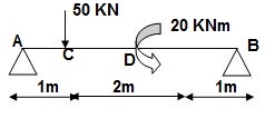
Find: ϴA& ΔC?
Solution:
∑MA = 0
-50 x 1 + VB x 4 + 20 = 4VB = 30
VB = 7.5 KN
VA + VB = 50
VA = 42.5KN
BMA = 0
BMB = 0
BMC = 42.5 x 1 = 42.5 KNM
BMDL = 42.5 x 3 – 50 x 2 = 27.5 KNM
BMDR = 7.5 x (1) = 7.5 KNM
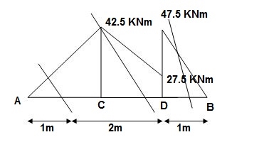
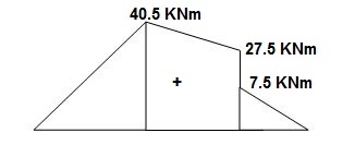
A1 = 1 / 2 x 1 x 42.5/EI = 21.25/EI
A2 = 1 / 2 x 2 x 15/EI = 15/EI
A3 = 27.5/EI x 2 = 55/EI
A4 = 7.5/2EI x 1 = 3.75/EI
Elastic curve:
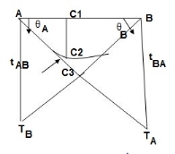
Slope &Deflection:
 t AB = {Area}A-B x xA
= (A1x1 + A2x2 + A3x3 + A4x4)@A
= 21.25/EI x [2/3 x (1)] + 15/EI(1 + 1/3 x 2) + 55/EI(1 + 1)+ 3.75/EI(3 + 1/3 x 1)
= 14.16/EI + 25/EI + 110/EI + 12.5/EI
= 161.66/EI
 t BA = Area(B-A) x xB
= {A1x1 + A2x2 + A3x3 + A4x4}@B
= 1/EI {21.25(3 + 1/3 x 1) + 15(1 + 2/3 x 2) + 55(2) + 3.75 x 2/3}
= 218.33/EI
ϴA ≈ tan (ϴA) = t BA/4
 ϴA = 218.33/4EI = 54.58/EI ( )
 ϴB ≈ tan (ϴB) = t AB/4 = 161.66/4EI = 40.41/EI ( )
To find ΔC
t BA/4 = C1C3/1
C1C3 = 54.58/EI
 C1C2 = t CA = Area CA x xC
= A1xC
= 21.25/EI (1/3 x 1)
= 7.08/EI
ΔC = C1C3– C1C2
 = 54.58/EI – 7.08/EI
= 47.5/EI ( )
Key takeaways


Slope deflection methods: means it is a method or tool by which we find out how a structure or a member of a structure behaves when subjected to certain excitation.
In other words finding out internal forces (axial force, shear force, moment), stress, strain, deflection, etc in a structure under applied load conditions.
1. Fixed End Moments: Standard Cases Fixed End Moments
Standard Cases
1.
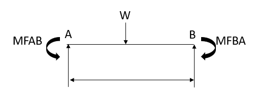

2.


3.
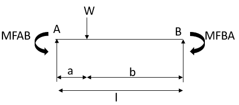

4.


5.
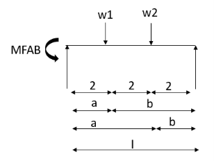


2. Derivation of slope Deflection Method
In beam, a continuous beam ABCD, consider AB part and take fixed end moments and rotation at support as given below
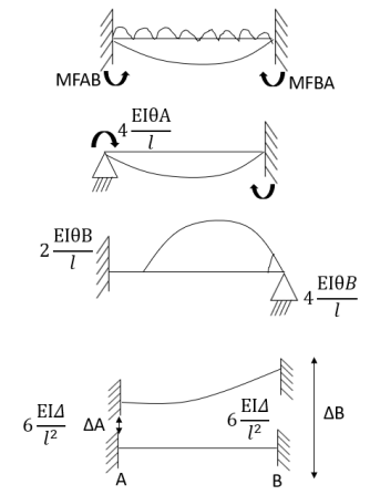
As per the diagram
Slop deflection equations are


3. Slope Deflection Method


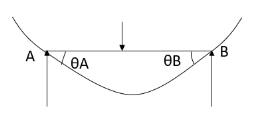
At support  form
form 
At the simply supported end
2.  is always zero.
3.  is always zero.
4. M Cantilever
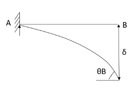


2.  At fixed end
4. Types of numerical for slope deflection method
1. The beam is without sink (  is zero.)
2. Beam with sink (is given)
3. Analyze of the frame without sink
4. Analyze the frame with the sink.

Steps for analysis of the slope deflection method.
1. Find unknown slope .
.
2. Find fixed end moment
3. Apply the slope deflection equation.


4. Use the joint equilibrium equation at the joint.
5. Find final moments.
6. Find relation by equation &Draw SFI
7. Draw BMD
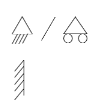


1) Analyze the continuous beam shown in figure Draw also B.M. and S.F. 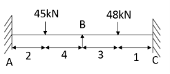
Step-1 Find fixed end moments


Step-II Slope deflection method


Step-III Apply equilibrium condition at joint


Step-IV Find final moments.


Step-V Find reaction

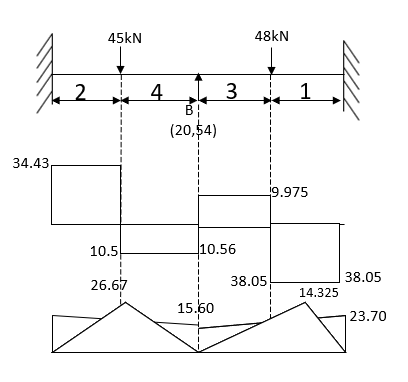
S.F. at A Take a moment at A is


SFD & BMD
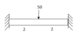
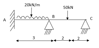
2) Determine support moments & draw BMD for the beam shown by using S.D.


2. Find fixed end moments
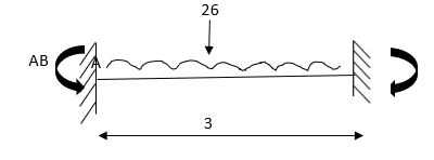


For BC Beam


3. Apply the SD equation
AB=>


BC=>


Apply equilibrium condition joint B


 ------- due to Hinge support


Put in equation (1) (2) (3) & (4)


Draw BMD Diagram
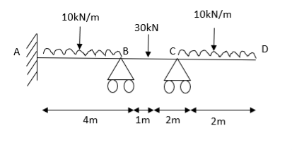
4. Analyze the continuous beam ABCD by S.D. method draw BMD

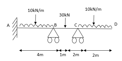
Modify Diagram
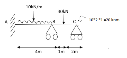


Apply S.D. equation


Joint equilibrium equation
Joint at B


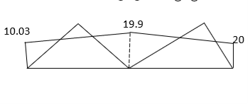
5. Analyze the continuous beam as shown in the figure by S.D. method Draw BMD

Find fixed end moment
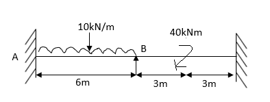
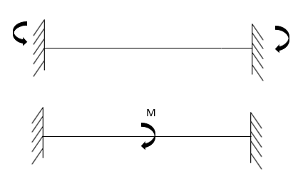

 KNM
KNM


S.D. equation
Span AB


Joint equilibrium equation
Joint B.


 KNM
KNM


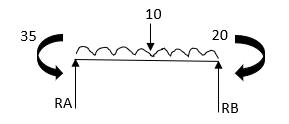


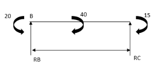


SFD
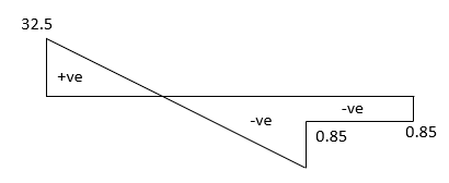
BMD

6. Analyze the continuous beam by S.D. equation
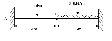


Apply S.D. equation
AB=>


 2)
2)
BC=>


Joint equilibrium condition


BMD
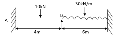

7. Analysis of fixes beam by S.D method
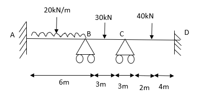
Step 1) Dki = 2 
Step 2) Find Fixed End Moments
Solution:
For AB
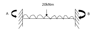


For BC


For CD


Apply S.D. equation


Joint equilibrium condition


8. Determine the final moments by slope deflection method take EI are constant.
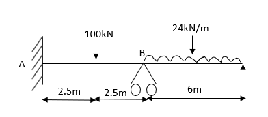
Step 1) Dki = 2
Step 2) Find fixed end moments


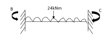


Step 3) Apply S.D. equation


For beam BC

 --------(3)

 -------(4)
OR
For member, BC apply modified equation


Step4)


9.5 + 1.46 EI  + 0.33EI
 -------(A)

0 -------(B)
Equating equation A & B get 

OR
Apply this condition to the modified equation


Step 6) BMD

2. Problems based on sink
Sink means deflection which occurs due to load which is acting on the beam
Note: always take EI in terms of KNM2


1) Analyze continuous beam ABCD having 
Point B is sunk by 2.5mm also draw BMD
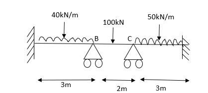
Solution:
Step 1) Dki = 2 


Step 2) Fixed end moments


STEP 3) Apply S.D. equation
AB=> ,l = 3m


BC=>


Apply equilibrium condition
Joint B


Joint C


 KNM
KNM
 KNM
KNM
 KNM
KNM

 KNM
KNM
 KNM
KNM
BMD

2) Determine the moment at the end of the fixed support A of the propped cantilever shown
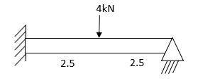
Take EI Draw BMD
CASE 1) … because support at the same level
STEP 1) Dki = 1
Step 2) Fixed end moments


AB =>


 simply supported end


Case 2) 
AB =>


Equilibrium Equation


Frames


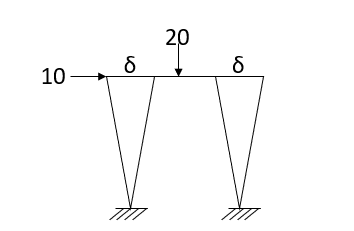
 occurred only in column
 is zero in the beam
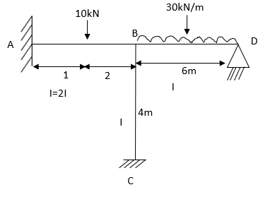


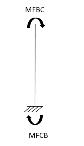


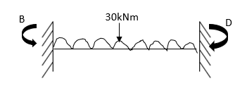


AB =>


Equilibrium condition
Joint at B


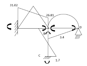
2. Analyze the frame by SD method by BMD

Find fixed end moments
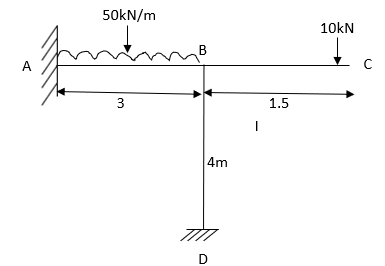


 ----due to no loading
S.D. equation
AB =>


BD =>


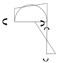
3. Equilibrium condition joint B


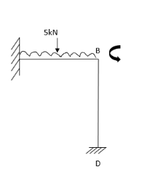


BMD
3. Analyze the frame shown in Figure support A is fixed B& C are winged. Draw BMD
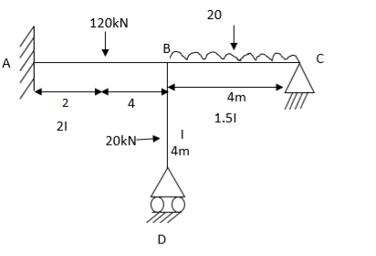
Find a fixed end


S.D. equation
For AB Span l =6m,  ,I =2I,


For BD Span l =4m,  ,I =I,


For BC Span l =4m,  ,I =1.5I,


Equilibrium condition joint B


 +
+ +
+  =0
=0
-16.67+3.83 +
+ +
+ ---------(A)
 ------(B)
 --------(C)
Equating Equation A, B & C you will get 
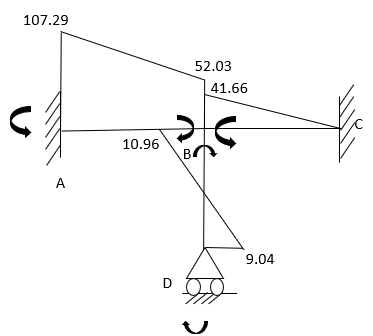
3. Problem on sway Frame
Example: 1] Analyze the frame shown in fig slope deflection method
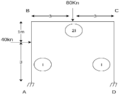
Step 1) Sway Frame: due to lateral loud frame in sway
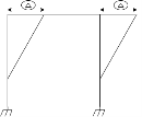
Find Fixed Ends Moments:
M FAB =  =
=  = 7.5KKNM
MFBA =  =
=  = -22.5KNM
M FBC = M FCB = =
=  =
=  60 KNM..
Apply Slope Deflection equations
For AB: ƟA=0, ƟB =?
MAB = MFAB (2ƟA+ ƟB-
 )
)
MAB = 7.5 +  ------------1)
MBA = -22.5 +  ---------------2)
For BC:  =?
=?
MBC = +60+ (
( ) -------3)
MCB = -60+ (ƟB
(ƟB ) -------------4)
MDC = MF DC (2ƟD+ ƟC-
 )
)
MDC =  (ƟC-
(ƟC- ) ---------5)
MCD =  (2ƟC-
(2ƟC- ) --------6)
4) Apply joint equilibrium equation
MBA+MBC = 0
-22.5 +  = 0---------------(A)
MCB+MCD = 0
-60+ (ƟB
(ƟB ) +
) + ( 2ƟC-
 )= 0 ------------(B)
Shear equation: HA +HD -40= 0 --------------7)
For AB Column
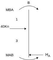
- HA 4 +MAB +MBA+ 40 *1=0
4HA = MAB + MBA+ 40 *1
Put Equation 1&2
4HA =7.5 +  -----(8)

This Fig 4HD = MDC+MCD
Put Equation 5 & 6
4HD =  (ƟC-
(ƟC- ) +
) + ( 2ƟC-
 ) ---------9)
Put equation 8 & 9 in Equation (7) Equation u will get equation (C)
Then Equating Equation (A,B,&C)
QB = -39.25/EI
QC = 19.25/EI
 = 110/EI
Final moments
MAB = 29.12 KNM
MBA = -20.5 KNM
MBC = 20.5 KNM
MCB = -60.51 KNM
MCD = 60.51KNM
MDC = +50.875 KNM
Key takeaways
Steps for analysis of the slope deflection method
1. Find unknown slope .
.
2. Find fixed end moment
3. Apply the slope deflection equation.


4. Use the joint equilibrium equation at the joint.
5. Find final moments.
6. Find relation by equation &Draw SFI
7. Draw BMD
1. Concepts – i) Moment at simply supported end is always zero.
ii) Moment at fixed & intermediate is created
2. Formula:
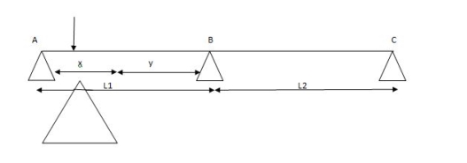
For span ABC

 MAl1 + 2MB (l1+l2) + Mcl2 = 6a1x1 + 6a2x2
l 1 l2
For different I -


 MAl1 + 2MB (l1+l2) + Mcl2 = 6a1x1 + 6a2x2


 I1 I1 I2 I2 l1I1 l2 I2
Area due to loading:
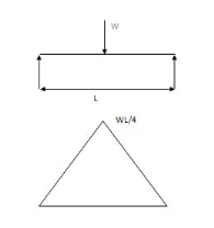
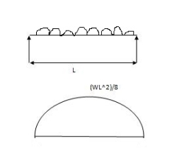
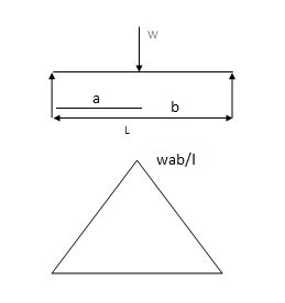
Case (1) Both ends are simply supported end
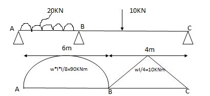
2) 6a1x1 = A = 2 x 6 x 90 = 360 A2 = 1 x 4 x 10 = 20m2

 3 2
3 2

 x1 = 6/2 = 3m x2 = 4/2 = 2m
6a1x1 = 6 x 360 x 3 = 1080

 l1 6
l1 6
6a2x2 = 6 x 20 x 3 = 60

 l2 4
l2 4
3) Apply 3 moments theorem
For span ABC
MAl1 + 2MB (l1+l2) + Mcl2 = 6a1x1 + 6a2x2

 l 1 l2
MA = MC = 0 l 1=6m l 2 =4m
0 + 2MB (6+4) + 0 = 1080 + 60
2MB (10) = 1140
S.F.D. Due to external load

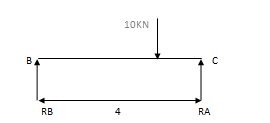
 RA = Wl = 20x6 = 60 KN RB = W = 10 = 5 KN


 2 2 2 2
RB = Wl = 20x6 = 60KN RB = W = 10 = 5 KN


 2 2 2 2
2) Due to moment

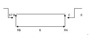
EMA=0 EMB = 0
 RB x 6 – 57 = 0 RC x 4 + 57 = 0
RB = 9.5 KN RC = 14.25 KN
Efi = 0
RA + RB = 0 RC + RB = 0
RA = - 9.5 KN RB = 14.25 KN
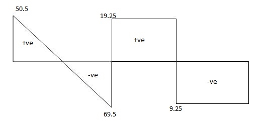
Total reaction:
RA = 50.5 KN
RB= 69.5 KN
RC = 5-14.25 = - 9.25 KN
RB = 5 + 14.25 = 19.25 KN

-2 One end is fixed & other is Hinge
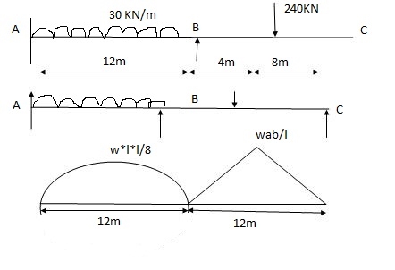
A1 = 2 x wl2 x 12 = 2 x 30 x 122 x 12 = 4320 mm2


 3 3 8
3 3 8
 x1 = l1 = 12 = 6 = 6m

 2 2
2 2
 A2 = 1 x Wab x 12 = 1 x 240 x 4 x 8 x 12 = 3840 mm2

 2 2 12


 x1 = l2 = 12 = 6m x1 = L + a x2 = l +b

 2 2 3 3

Apply 3 Moment Theorem
A’AB

 MA1l1 + 2MA (l1+ l1 ) + MB l1 = 6a1x1 + 6a1x1
l1 l1
0 + 2MA (0+12) + 12MB = 0 + 6 x 4320 x 6
 12
12
 24MA + 12MB = 12960 (1)
Span ABC
 MAl1 + 2MB (l1+ l2) + MCl2 = 6a1x1 + 6a2x2
 l1 l2
l1 l2
12MA + 2 MB (12 + 12) + 0 = 6 x 4320 x 6 + 6 x 3840 x 6

 12 12
12 12
 12MA + 48 MB = 24480 (2)
Add eqn. (1) & (2)
MA = 325.71 KNM
MB = 428.57 KNM
Draw S.F.D.
1) Due to external load

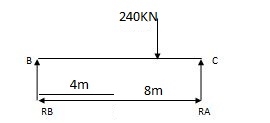


 RA = wl = 30 x 12 = 180 KNW RB = wb = 160 KN
2 2 l


 RB = wl = 30 x 12 = 180 KN RC = wa =120 KN =
2 2 l
2) Due to moment

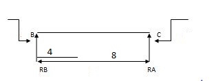
EMA=0 EMB=0

 325.71 – 428.57 + RB x 12 = 0 428.57 + RC x 12 = 0
RB = 8.57 RC = 35.71 KN


RA = 8.57 KN RB = 35.71 KN
Total Reaction:
RA = 180 – 8.57 = 171.43 KN
RB = 180 + 8.57 = 188.57 KN
RB = 160 + 35.71 = 124.29 KN
RC = 120 + 35.71 = 155.71 KN
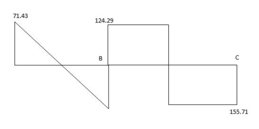

(3) Both ends are fixed
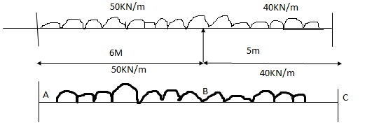

A1 = 0
 xi = 0


 A1 = 2 x wl2 x 6 = 112.5 A2 = 2 x wl2 x 5 = 125
 3 8 3 8


 x1 = 6/2 = 3 x2 = 5/2 = 2.5
A12 = 0 x12 = 0
Span A1AB
MAl1+ 2MB (l11 + l1) + MBl1 = 6a11x11 + 6a1x1

 l11 l1
0 + 2MA (0+6) + 6MB = 0 + 6 x 112.5 x 3
 6
6

12MA + 6MB = 337.5
Span ABC
MAl1+ 2MB (l11 +l1 ) + MC = 6a1x1 + 6a2x2

 l1 l2
l1 l2
6MA + 2 MB (6+ 5) + MC x 5 = 6 x 112.5 x 3 + 6 x 175 x 2.5

 6 5
6 5

 6MA + 22MB + 5MC = 712.5 (2)
Span BCC
MBl2+ 2MC (l2 + l12) + MC1l12 = 6a2x2 + 6a12x12

 l2 l12
5MB + 2MC (5+0) + 0 = 6 x 125 x 2.5


 5MB + 10 MC = 375 (3)

MA = 17.33 KNM
MB = 21.59 KNM
MC = 26.70 KNM
Reaction due to external load


RA = wl = 150 RB = wl = 100 KN

 2 2
2 2
RB = wl = 150 RC = wl = 100 KN

 2 2
2 2
Reaction due to moments


17.33 – 21.59 + RB x 6
RB= 1.022
RB = 0.71 RA = 0.71 RC = 1.022
Total Reaction:
RA = 150 – 0.71 = 149.29 KN
RB = 150 + 0.71 = 150.71 KN
RB = 100 – 1.02 = 98.98 KN
RC = 100 + 1.02 = 101.02 KN
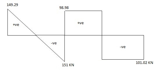

Overhung Numerical:


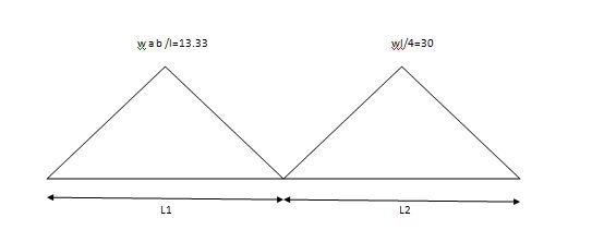


 A1 = 1 x 3 x wab A2 = 1 x wl x 4
2 l 2 4
 1 x 3 x (20 x 1 x 2) = 20m2 A2 = 60 m2
 2 3
2 3
x1 = 4 /3 3 +1 = 4/3 = 1.33
 3
3
Span ABC
MAl1+ 2MB (l1 + l2) + MCl2 = 6a1x1 + 6a2x2

 l1 l2
l1 l2
0 + 2 MB (3+ 4) + 15 x 4 = 6 x 20 x 1.33 + 6 x 60 x 2

 3 4
3 4
14MB + 60 = 53.2 + 180
MB = 173.2 KN
Key take ways
1. Find the reaction
2. Apply three moment theorem
3. Draw SFD
4. Draw BMD
It is used for the analysis of indeterminate structures. In this method solution of simultaneous equations of the slope, the election method is replaced by an iterative distribution procedure.
1. Carryover moment: A moment is allowed to a member permitting rotation at the point of application and keeping the other end fixed additional moment develops at the far end this is called.
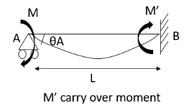
2. Carryover factor:-the ratio of carryover moment to applied moment is called carry-over factor.
Carryover factor=
3. Stiffness:- Moment required to rotate an end by a unit angel when rotation is permitted at that end is called stiffness of the beam.
Stiffness of the beam AB=
4. Distribution factor:-When a moment is applied to a right joint where a number of members are meeting, the applied moment is shared by the members meeting at the joint. The ratio of the moment shared by a member to the applied moment at the joint is called.
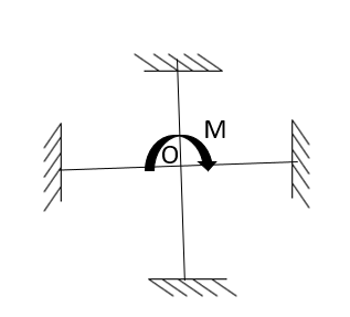

Examples:
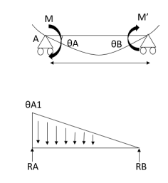


Then consider at the B end
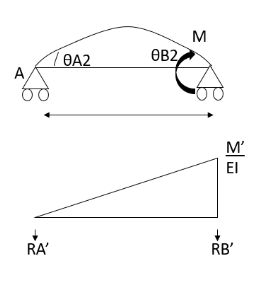


Carryover factor = 


Put 


Distribution factor =>
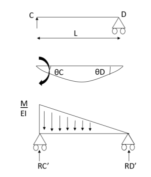
2. Continuous beam with simply supported ends lets CD lost span let
M act at joint C.


5. Carryover factor:-
Types of toe and support.
Relative stiffness factor (I/l)


5. Distribution factor: A moment which tends to rotate without translation a joint to which several members are connected will be divided amongst connected member in proportion to their stiffness.
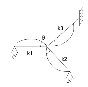

6. Carryover moment:-when a movement is applied to produce rotation without translation at the near supported and B of a beam whose father end A is fixed the carry over the moment  at the further and is ½ are applied movement m I is of the same as the applied moment.
7. Application of MD method to continuous beam with fixed ends:-
8. Steps for analysis of moment distribution method.
Distribution factor is=
K=stiffness -it depends on the support condition.
1. Far end fixed &intermediate support =
2. The far end simply supports = 
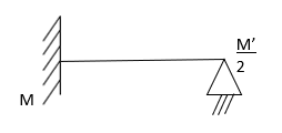
COF -> support
O -> simply support
½ -> fixed
½ -> intermediate
Examples:
AB=>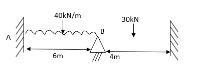


1) Draw distribution table
Joint | Member | K |
|
|
B | BA
BC |
|
| 0.4
0.6 |
2) Moment distribution Table
0.4 | 0.6 | |||
Member | AB BA | BC CD | ||
Fixed end
Balancing | 120 - 120
42 | 15 -15
63 | ||
COF
Balancing | 21 0 0 | 31.5 | ||
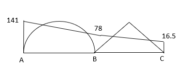
Final moments
| 141 -78 | 78 16.5 | ||


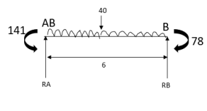
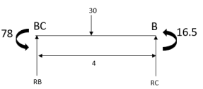


SFD
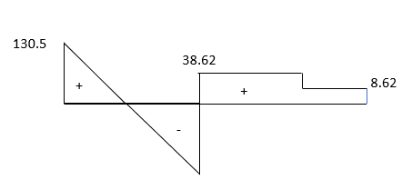
BMD
2. Analyze the given beam ABCD by Moment Distribution method
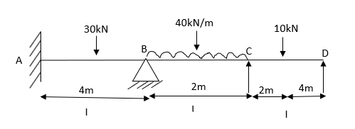
1) Find fixed moment

 KNM
KNM
 KNM
KNM
 KNM
KNM
 KNM
KNM
 KNM
KNM
Step 2)
JOINT | MEMBER | K |
|
|
B | BA
BC
|
|
5EI | 0.2
0.8 |
C | CB
CD |
|
4.5EI | 0.89
0.11 |
3) Moment Distribution Table
0.2 | 0.8 |
| 0.89 | 0.11 | ||||
Members | AB BA 15 -15
| BC CB 13.33 -13.33
| CD DC 8.89 -4.44
2.22 + 4.44 | |||||
Fixed End | ||||||||
Balancing | ||||||||
Initial Moments
Balancing | 15 -15
0.331 | 13.33 -13.33
1.34 1.98 | 11.1 0
0.25 | |||||
COF
Balancing | 0.165
-0.19
| 0.99 0.67
-0.79 -0.59 |
-0.07 | |||||
COF
Balancing | -0.09
0.058 | -0.29 -0.39
0.22 0.34 |
0.04 | |||||
Final Moments | 15.075 -14.801
| 14.8 -11.32 | 11.32 0 | |||||
 KNM
KNM
 KNM
KNM
 KNM
KNM
 KNM
KNM
 KNM
KNM
 KNM
KNM
BMD

3. Analyze the given beam by M.D. method
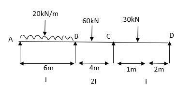
Step 1) Find fixed end moment


Step 2) Distribution Factor
Joint | Members | K |
|
|
B | BA
BC |
|
2.5 EI | 0.2
0.8 |
C | CB
CD |
|
| 0.66
0.33 |
Moment distribution table
0.2 | 0.8 |
| 0.66 | 0.33 | ||||
Members | AB BA | BC CB | CD DC | |||||
Fixed End | 60 -60
-60 -30
| 30 -30
| 13.33 -6.66
3.33 +6.66
| |||||
Balancing | ||||||||
Initial Moments
Balancing | 0 – 90
12 | 30 -30
48 8.8 | 16.66 0
4.40 | |||||
COF
Balancing |
-0.88 | 4.4 24
-3.52 -15.84 |
-1.92 | |||||
COF
Balancing |
1.58 | -7.92 -1.76
6.33 1.16 |
0.58 | |||||
COF
Balancing |
- 0.11 | 0.58 3.16
-0.46 -2.08 |
-1.04 | |||||
COF
Balancing |
0.20 | -1.04 -0.23
0.83 0.15 |
0.07 | |||||
Final Moments | 0 -77.21 | 77.21 -12.64 | 12.75 0 | |||||
BMD
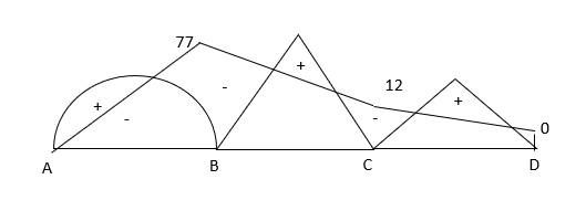
3) Analyze the given frame by MD method
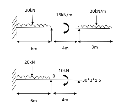
Step 1) Find Fixed End Moments


Step 2) Distribution table
Joint | member | K |
|
|
B | BA |
| 1.41 | 0.47 |
| BC |
| 1.41 | 0.53 |
Step 3) Moment Distribution Table
0.47 | 0.53 | |||
Member | AB BA | BC CB | ||
External moment
Fixed end
balancing |
60 - 60
| 135
2.5 -2.5
-1.25 2.5 | ||
Initial Moment
Balancing | 60 -60
27.61 | 1.25 135
31.13 | ||
COF
Balancing | 13.8 0
0 | 0
0 | ||
Final moments
| 73.8 -32.39 | 32.39135 | ||
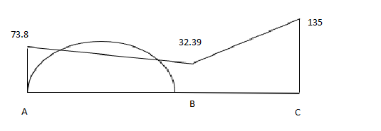
9. Problem-based on sink
1) Analyze the given beam ABCD having pt B is sink by 10mm
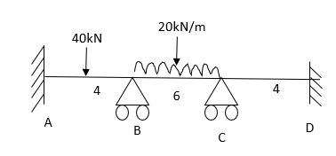
For AB Span 
 KNM
KNM

BC= +VE
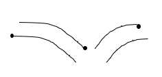


CD=0  No loading

Step 2) Distribution factors
Joint | Members | K |
|
|
B | BA
BC |
|
1.66 | 0.60
0.40 |
C | CB
CD |
|
| 0.40
0.60 |
Step 3) Moment Distribution Table
0.6 | 0.4 |
| 0.4 | 0.6 | ||||||||
Members | AB | BA | BC | CB | CD | DC | ||||||
Fixed end
Balance | 34.25
| -5.75
-28.74
| 53.66
-19.16 | -66.33
26.53 | 0
39.79 | 0
| ||||||
COF Balancing | +14.37 | -7.95 | 13.26 -5.30 | -9.58 +3.83 |
+5.74 | 19.89 | ||||||
COF Balancing | -3.97 |
-1.14 | 1.91 -0.76 | -2.65 1.06 |
1.59 |
| ||||||
COF
Balancing | -0.57 |
-0.31 | 0.53
-0.21 | 0.38
0.15 |
0.22 | 0.79 | ||||||
Final Moments | 15.34
| -43.89 | 43.89 | -46.61 | -46.61 | 20.68 | ||||||
2) Draw BMD by Moment Distribution Method and C support is sink by 25mm
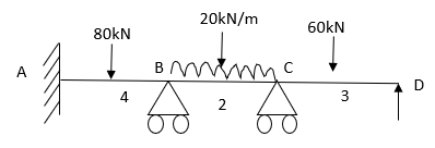
For AB 


For BC  mm
mm


For CD  mm
mm


Step 2) Distribution factor
Joint | Members | K |
|
|
B | BA
BC |
|
| 0.33
0.66 |
C | CB
CD |
|
| 0.66
0.33 |
Step 3) Moment Distribution Table
0.33 | 0.66 |
| 0.66 | 0.33 | ||||||||
Members | AB | BA | BC | CB | CD | DC | ||||||
Fixed end | 40 | -40 | 149.16 | 135.83 | -40.83 42.91 | -85.83 +85.83 | ||||||
Final Balance | 40 | -40 -36.02 | 149.16 -72.04 | 135.83 -91.02 | 2.08 -45.51 | 0
| ||||||
COF Balancing | -18.01 |
15.02 | -45.51 30.04 | -36.02 23.77 |
11.89 |
| ||||||
COF Balancing | 7.505 |
-3.92 | 11.89 -7.85 | 15.02 -9.91 |
-4.957 |
| ||||||
COF
Balancing | -1.96 |
1.64 | -4.96
3.28 | -3.93
2.59 |
1.296 |
| ||||||
Final Moments | 29.28 | -63.28 | 64.01 | 36.33 | -35.20 | 0 | ||||||
Examples:
1) Problems based on frame
Non- sway
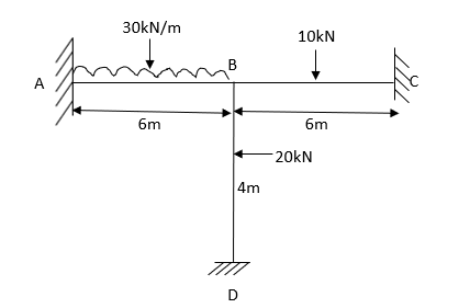
Step 1) Fixed End Moments


Step 2) Distribution Factor
Joint | Members | K |
|
|
B | BA
BD
BC |
|
2.33 | 0.28
0.43
0.28 |
Step 3) Moment Distribution Table
0.28 | 0.43 | 0.28 | ||||||
Members | AB | BA | BD | BC | CB | DB | ||
Fixed end
Balance | 90
| -90
20.3
| 10
31.17 | 7.5
20.3 | -1.5 | -10
| ||
Cot Balancing | 10.15 | 0 0 | 0 0 | 0 0 |
10.15 | 15.58 | ||
Final |
100.15 |
-69.7 |
42.17
|
27.8 |
2.65 |
5.58 | ||
BMD

Determine Moments of the given figure by moment Distribution Method
Step 1) Non-sway
Step 2) Fixed End moments

 knm
knm

Step 3) Distribution factor
Joint | Members | K |
|
|
B | BA
BC |
|
| 0.43
0.57 |
C | CB
CD |
|
| 0.64
0.36 |
Step 4) Moment Distribution table
0.43 | 0.57 |
| 0.64 | 0.36 | |||||||
Members | AB | BA | BC | CB | CD | DC | |||||
Fixed end | 0 | 0 | 22.5 | -22.5 | 0
| 0 | |||||
Initial Balance | 0 | 0 -0.96 | 22.5 -1.28 | -22.5 +1.14 | 0 +0.81 | 0
| |||||
COF Balancing | -0.48 |
0.24 | +0.57 0.32 | -0.64 0.40 |
0.23 |
| |||||
COF Balancing | 0.12 |
-0.086 | 0.20 -0.114 | 0.16 -0.10 |
-0.057 |
| |||||
Final Moments | -0.36 | -0.806 | 0.806 | -3.57 | -0.637 | 0 | |||||
Analysis the given frame as shown


Distribution Factor
Joint | Members | K |
|
|
B | BA
BD
BC |
|
3.455 EI | 0.40
0.28
0.32 |
Moment Distribution Table
0.40 | 0.28 | 0.32 | |||||||
Members | AB | BA | BD | BC | CB | DB | |||
Fixed end | 106.66 | -53.33 | 10 5 | 40 20 | -40 40
| -10 +10 | |||
Initial Balance | 106.66 | -53.33 -8.66 | 15 -6.06 | 60 -6.43 | 0
| 0
| |||
COF Balancing | -4.33 | 0 0 | 0 0 | 0 0 |
|
| |||
Final Moments |
102.35
| -61.99 |
8.94 |
53.07
|
0 |
0 | |||
BMD
Problem-based on non-sway form
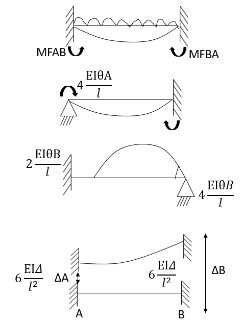


Distribution factor
Joint | Members | K |
|
|
B | BA
BC |
|
| 0.70
0.30 |
C | CB
CD |
|
| 0.30
0.70 |
Step 4) Moment Distribution table
0,70 | 0.30 |
| 0.30 | 0.70 | |||||||
Members | AB | BA | BC | CB | CD | DC | |||||
Fixed end | 30
-30 | -30
-15 | 90 | -90 | 30
15 | -30
30 | |||||
Initial
Balance | 0 | -45
-31.5 | 90
-13.5 | -90
13.5 | 45
31.5 | 0 | |||||
COF Balancing |
|
-4.72 | 6.75 -2.02 | -6.75 2.02 |
4.72 |
| |||||
COF Balancing |
|
-0.7 | 1.01 -0.3 | -1.01 0.3 |
0.7 |
| |||||
COF Balancing |
|
-0.1 | 0.15 -0.04 | -0.15 0.04 |
0.1 |
| |||||
Final Moments
|
0 |
-82.2 |
82.2 |
82.2 |
-82.2 |
0 | |||||


BMD
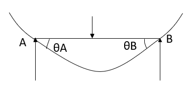
10. Problem-based on sway Frame
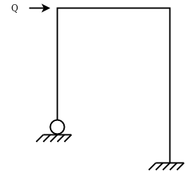 Concept: The carry over
  for fixed support
For Hinge support end moment 

 is not known.


Problems:
1) 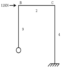 Analyze the given frame by moment distribution method take EI Constant
Step 1) Find Distribution Factor
Joint | Member | K | ƩK | D.F. | |
B | BA |
|
| 0.33 | |
BC |
| 0.67 | |||
C | CB |
|
| 0.67 | |
CD |
| 0.33 | |||
Step: 2 Non sway moment distribution moment Table
Members | AB BA | BC CB | CD DC |
Fixed End Balancing | 0 0 0 | 0 0 0 0 | 0 0 0 |
Final Moments | 0 0 | 0 0 | 0 0 |
Step 3: Assumption for sway Frame
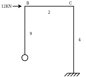


Step 4: Draw Sway Moment distribution Table
0.33 | 0.67 |
| 0.67 | 0.33 | ||||||
Member | AB | BA
| BC CB
| CD DC | ||||||
FEM Balancing | 0 | 8 | 0 | 0 | 9 | 9 | ||||
| -2.67 | -5.33 | -6.00 | -3.00 |
| |||||
| COF Balancing |
|
1 | -3 | -2.67 |
| 1.5 | |||
| 2 | 1.78 | 0.85 |
| ||||||
| COF Balancing |
|
-0.30 | 0.69 | 1 |
|
| |||
| -0.39 | -0.67 | -0.33 |
| ||||||
| COF Balancing |
|
0.11 | -0.33 | -0.30 |
| 0.17 | |||
| 0.22 | 0.20 | 0.10 |
| ||||||
| COF Balancing |
|
-0.03 | 0.10 | 0.11 |
| 0.05 | |||
| -0.07 | -0.07 | 0.05 |
| ||||||
| 0 | 6.11 | -6.11 | -6.62 | 6.62 | 7.83 | ||||
| ||||||||||
Horizontal thrust at A 


Actual Sway force of 12 KN

Step 6) Final Moments Table:
Member | AB BA | BC CB | CD DC | ||||
Non Sway Moment | 0 0 | 0 0 | 0 0 | ||||
Sway Moment | 0 | 6.11 | -6.11 | -6.62 | 6.62 | 7.83 | |
Actual Sway | 0 | +12.98 | -12.98 | -14.06 | +14.06 | +16.6 | |
Final Moment (Addition of Non Sway Moment +corrected moment by sway ) | 0 | +12.98 | -12.98 | -14.06 | +14.06 | +16.6 | |
 Correct Horizontal A reaction

2) A two hinged portal frame ABCD consist of a vertical columns AB, DC at 4m height if the beam BC of 3m the frame carried a vertical point load of 120kN on the beam at a distance of 1m from B find the reaction at support.
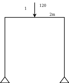
Solution:
(i) Non Sway analysis:

 and
and 
Step 2) Draw Distribution Factor Table
Joint | Member | K | ƩK | D.F. |
B | BA | 3EI/L= 3EI/4 = 0.75 EI |
2.08 EI | 0.36 |
BC | 4EI/L= 4EI/3=1.33 EI | 0.64 | ||
C | CB | 4EI/L = 4EI/3=1.33EI |
2.08 EI | 0.64 |
CD | 3EI/L= 3EI/4=0.75 EI | 0.36 |
Step 3) Draw Non sway moment distribution Table
0.36 | 0.64 |
| 0.64 | 0.36 | ||||
Member | AB BA | BC CB |
| CD DC | ||||
FEM Balancing | 0 -19.2 | 53.33 -26.66 -34.13 17.06 |
| 0 0 9.6 | ||||
COF Balancing |
-3.07 | 8.53 -17.07 -5.46 10.92 |
|
6.15 | ||||
COF Balancing |
-1.96 | 5.46 -2.73 -3.49 1.75 |
|
0.98 | ||||
Final Moments | 0 -24.23 | 24.24 -16.73 |
| 16.73 0 | ||||
Horizontal reaction 

 Sway force = 1.87 kN
(ii) Sway analysis
Step 4 )
Initial equivalent moments are negative.
 :
: 
0.36 | 0.64 |
| 0.64 | 0.36 | ||||
Member | AB BA | BC CB |
| CD DC | ||||
FEM Balancing | 0 -10 3.6 | 0 0 6.4 6.4 |
| -10 0 3.6 | ||||
COF Balancing |
- 1.15 | 3.2 3.2 -2.05 -2.05. |
|
-2.05 | ||||
COF Balancing |
0.35 | - 1.03 -1.03 0.66 0.66 |
|
0.35 | ||||
Final Moments | 0 -7.2 | 7.2 7.2 |
| -7.2 0 | ||||
Horizontal reaction 

Resolving force horizontally = 1.81 +1.81 =3.63kN
Actual Sway = 3
Sway 0 7.27 | 7.27 7.27 | -7.27 0 |
| +3.64 3.64 | -3.64 0 |
Non Sway 0 21.17 | -21.17 21.17 | -21.17 0 |


Key takeaways
The analysis of these symmetrical frame in which a joint translation is prevented can be performed in the same way as far as continuous beam
For symmetrical loading, symmetric quantities like bending moment displacement are symmetrical about the censorial vertical axis.
2. Anti-symmetrical frames:
If a frame whose joint do not translate laterally but are free to rotate is called anti symmetrical or unsymmetrical frames.
For anti-symmetrical loading symmetric quantities like bending moment displacement is zero at the point of censorial vertical axis.
Anti-symmetrical quantities like slope and shear force distributed about the censorial vertical axis.
Sway Correction Factor 
Analysis of frame with sway
Analysis the rigid frame shown in fig by M.D. method.
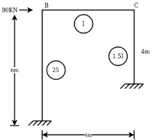
(i) Fixed end moment in all the members = 0
(ii) D.F
B | BA |
|
| 2.33EI | 0.57 |
BC |
|
| 0.43 | ||
C | CB |
|
| 2.5EI | 0.4 |
CD |
|
| 0.6 |

Conclude S = 80 KN

Sway Force
Consider FBD for column


SWAY ANALYSIS
Consider Sway on right hand side
 is
is 
 is
is 


Consider 
Moment distribution maybe carried out.
A B C D
10 | 0.5 10 | 0.5
| 0.5
| 0.5 20 |
20 |
| -5 | -5 | -10 | -10 |
|
-2.5
|
2.5 | -5 | -2.5 |
| -5 |
2.5 | 1.25 | 1.25 |
| ||
1.25
|
-0.32 | 0.63 | 1.25 |
| 0.63 |
-0.32 | -0.62 | -0.62 |
| ||
-0.16
|
+0.16 | -0.31 | -0.16 |
| -0.31 |
0.16 | 0.08 | 0.08 |
| ||
0.08
|
-0.02 | 0.04 | 0.08 |
| 0.04 |
-0.02 | -0.04 | 0.04 |
| ||
+8.67 | -7.32 | -7.32 | -10.66 | 10.66 | 15.35 |


Sway Correction Factor 


Arbitrary Sway | +8.67 | +7.32 | -7.332 | -10.66 | +10.66 | +15.37 |
Actual Sway | 8.67×6.37= 53.88 | 7.3×6.2= 45.44 | -45.44 |
|
|
|
Non Sway | +20.42 | -12.44 | +12.44 | +3.35 | -3.35 | -1.77 |
Final | +74.30 | +33.05 | -33.05 | -62.75 | +62.7 | +93.62 |
Key takeaways
1. Find end moment in all the members
2. Distribution factor
3. Sway force
4. Sway analysis
5. Find moment distribution
6. Find sway correction factor
1. Portal method:
Steps
1) Assume first assumption -> mark point of contra flexure at centre of each column & beam
2) Apply 2nd assumption -> Horizontal shear is double at interior column.
3) Find P& Q force.
4) Find moment at beam = always same as moment of column.
5) Find shear force at beam=moment at 
1) Analyse the given figure by portal method
Step 1) 1st Assumption-> Mark point of contra flexure of each member
Step 2) 2nd Assumption -> Interior Horizontal shear is double than (extreme) lost member.
P+2P+P=12
P=3KN
Q+2Q+Q=12+24
Q=9KN
Step 3) Moment at the end of column


Step 4) Moment at column


Step 5) Moment at the end of roof Beam

Step 6) Moment at the end of floor Beam


Step 7) Shear force in Beam


Similarly, 

2) Analyse the given figure by portal Method
Mark point of contra flexure at centre of each beam& column.
Horizontal share is double at interior column.
Find p & q
P+2P+P=20
P=5kN
Q +2Q +Q=50
Q=12.5KN
Moment at column AD= =
=
MBE=
MCF=
MDG=MGD=
MEH=MHE=
MFI=MIF=
3) Analysis the given figure by portal method
P+2P+2P+P=25
4P=25
P=4.16
Q+2Q+2Q+Q=60
6Q=60
Q=10KN
MAE=MEA= =4.16
=4.16
MBF=MFB=
MCG=MGC=
MDH=MHD=
MEI=MIE= =10
=10
MFI=MIF=
MGK=MKG=
MHL=MLH=
Shear force
SFAB=20.8/2=10.4
SFBC=20.8/3=6.93
SFCD=20.8/4=5.2
SFEF=60.8/2=30.4
SFFG=60.8/3=20.26
SFGH=60.8/4=15.3

3) Analysis the given figure by portal method
P=3.33 Q=3.33 R=10


4) Analysis the frame shown in figure below by portal method
Step1> Apply 1st assumption
2> Apply 2nd Assumption-> Horizontal shear is double at interior member
P+2p+p=25
P=6.25KN
Q+2Q+Q=25+50
Q=18.75KN
3) Moment at the end of column


4) Moment at the end of floor column


5) Moment at beam

6) Moment at end of beam


7) Shear force at (beam) floor

Key takeaways
1) Assume first assumption -> mark point of contra flexure at centre of each column & beam
2) Apply 2nd assumption -> Horizontal shear is double at interior column.
3) Find P& Q force.
4) Find moment at beam = always same as moment of column.
5) Find shear force at beam=moment at 
2. Cantilever Method
Assumption:
Step-1 Find centroidal distance
Take moment about A


Step-2> As per 2nd assumption
Vertical stresses in column are proportional to their absence from the C.G. of the columns in that storey.
1> Consider top storey
Assume  is downward &
 is upward.


Put  values

Take about point of contra flexure i.e. at 0 point.
Clockwise +ve Anti clockwise -ve
Upward +ve Downward -ve


Consider lowest storey
Assume  are downward
 are upward
As per 2nd assumption


Take a moment about 0 point.


Step-3) To find S.F. in proof Beam
S.F. in AB=1KN
SF in BC=1+0.42=1.42
SF in CD=1+0.42-0.28=1.14
S.F. in EF=6-1=5KN
S.F. in FG=6+2.57+1-0.48=7.15KN
SF in GH=6+2.37-1.71-1-1-0.42+0.28=5.72KN
Step-4) To find Moment in roof beam
Formula => Moment in roof beam=S.F. in that Beam*Balt of Beam span


> To find moment in floor beam


Step -5) To find Moment in column


Moment in column of floor beam


Step-6) S.F. in column
S.F. AE=2/1.5=1.33KNM
SF BF=5.55/1.5=3.7KN
S.F. CG=6.9/1.5=4.6KN
S.F. DH=3.42/1.5=2.28KN
S.F. in column EI=1.33*1.5+x+2=10
X=4KN
S.F. in column FJ=3.725*1.5+x+2=(17.85+10)
X=11.128KN
S.F. in column GK=4.667*1.5+x*2=(17.14+17.85)
X=13.99KN
S.F. in column HL=2.28*1.5+x+2=(17.142)
X=6.86KN
Key takeaways
1. Find censorial distance
2. As per 2nd assumption
3. To find S.F. in proof Beam
4. To find Moment in roof beam
5. To find Moment in column
6. S.F. in column
1. Flexibility matrix method
The flexibility method is based upon the solution of "equilibrium equations and compatibility equations". There will always be as many compatibility equations as redundant. It is called the flexibility method because flexibilities appear in the equations of compatibility. Another name for the method is the force method because forces are the unknown quantities in equations of compatibility.
DQ= [DQL]+[F][Q]-compatibility equation
DQ=External displacement at redundant position
 Displacement at the redundant position because of applied loading

F=flexibility matrix


1) Redundant reaction
It is also called as Force Method
In this method, horizontal displacement is neglected
Degree of indeterminacy=R-E
R=Reaction
E=Equilibrium equation


=4-2
=2
The redundant structure is 2.

1) Use flexibility Matrix Method
Step 1)


=4-2
=2
Redundant structure is 2.

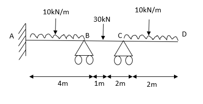
Zone | Limit | Origin | M |
|
|
CD | 0-2 | C | 0 | 0 | x |
DB | 0-2 | D | -40 | 0 | x+2 |
BA | 0-6 | B |
| x | x+4 |


 = - 11100 /EI


=333.33/


2) Analyze the beam by flexibility method
Step 1)

=4-2
=2
The redundant structure is 2.

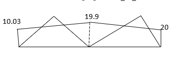
Zone | Limit | Origin | M |
|
|
CD | 0-4 | C |
| 0 | x |
DB | 0-2 | D |
| 0 | x+4 |
BA | 0-6 | B |
| X | x+6 |


= -19440 /EI


=-640-2600-51480
= -54780 /EI


=576 /EI

 KN
KN


 KN
KN
3) Using the flexibility method analyze the fixed beam AB as shown Draw SFD & BMD
Step 1)

=2

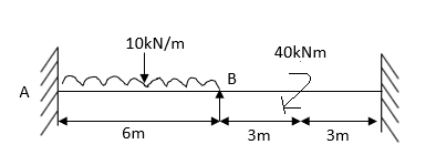
Zone | Limit | Origin | M |
|
| EI |
BC | 0-2 | B |
| 1 | X | I |
CA | 0-3 | C |
| 1 | x+2 | 2I |
Compatibility Equation


 /EI
/EI

=-380.31 /EI


=2+1.5
=3.5 /EI


=2+5.25
=7.25/ EI

=2.66+19.5
=22.16 /EI

M=-21.28 KNM


 KN
KN


 KNM
KNM
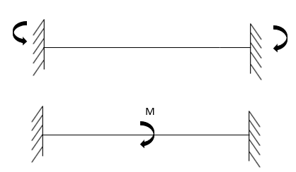
Key takeaways
1. Find Degree of indeterminacy
2. Find reactions (RA & RB)
3. Flexibility methods
It is a matrix method that makes use of the members' stiffness relations for computing member forces and displacements in structures. The direct stiffness method is the most common implementation of the finite element method (FEM).
It is also called a displacement method.
[S]+[D]+[AM]=[AJ]
S = Stiffness Matrix
[D]=unknown joint displacement
i.e. 
AM=Fixed end moments at particular points
AJ=External moment
1. Important Points
When  is present in your frame

2. Steps for analysis at stiffness matrix
1-> Find known rotation i.e. 
2 -> Find fixed end moment
3 -> Find AM value
4 -> Find S matrix
5 -> Put in compatibility equation [S]+[D]+[AM]=[AJ]
6 -> Apply S.D. equation
1) Analyze the beam shown in the figure by stiffness method Take EI= constant
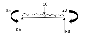
Step 1) Find fixed end moment
For Span AB
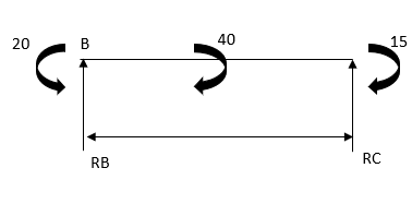


Span BC
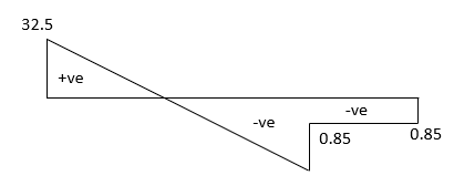


Step 2)

= -5+13.33
= 8.33


Step 3) Use compatibility equation
[S]+[D]+[AM]=[AJ]


Apply SD equation for span AB


2) Analyze the given figure by Stiffness Method
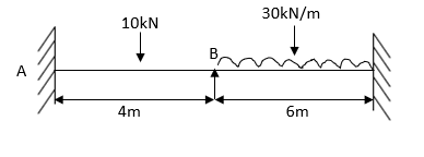
Step1) Find
Dki=
Step 2) Fixed end moments


Step 3) S.D. equation


Step 4) Stiffness Matrix


 =1.33
=1.33


= -3.34

=-13.33
Step 5) Compatibility Equation
[S+[D]+[AM]=[AJ ]


 /EI
/EI
 /EI
/EI


3) Analyse the given figure by Stiffness Method

Step 1) 
Step 2) Find fixed end moments


Step 3) S.D. equation


 -------(4)


Step 4) Stiffness Matrix


=1.11 


= -75

= -60+80
= 20
Step 5) Use compatibility equation
[S]{D} + {AM}={AJ}


4) Analyze the given beam shown in the figure by stiffness method
Take EI=
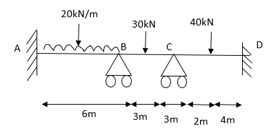
Step 1) Dki =?

Step 2) Find the fixed end


Step 3)

=125

= -135+60
=-75

Step 4) S.D. equation


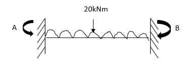

Step 5) Stiffness Matrix


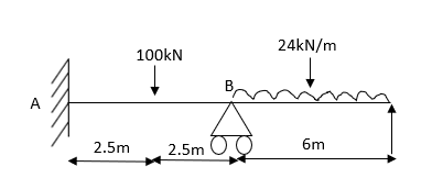

Step 6) Use compatibility equation
[S]{D}+{AM}={AJ}


 KNM
KNM

 KNM
KNM
 KNM
KNM
5) Analysis the given figure

Step 1) Dki = 2
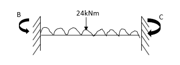
Step 2) Fixed End Moments


Step 3) S.D. equation


Step 4)

=-12.5+13.33
=0.83

Step 5) Apply compatibility equation
[S]{D}+{AM}={AJ}


 /EI
/EI


6) Analyze the given fig. By stiffness Matrix method take EI IS Constant
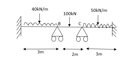


S.D. EQUATION


Stiffness Matrix

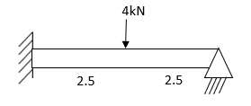
Apply compatibility equation
[S]{D}+ {AM}={AJ}


7) Analyze the given beam by stiffness method B is sink by 10mmEI=
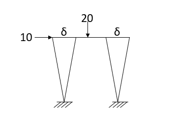


=126.33KNM


Apply S.D. equation


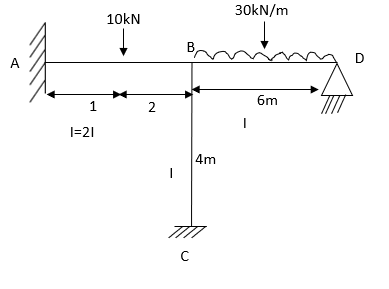
8) Analysis the beam by stiffness matrix method draw SFD & BMD
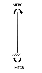


Apply S.D. equation


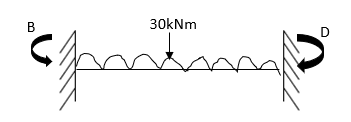
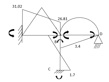
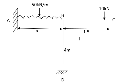


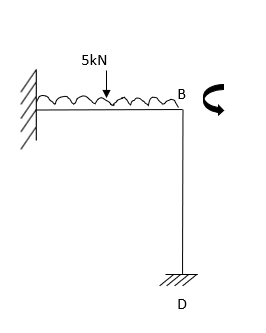


Draw SFD &BMD
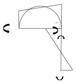
Key takeaways
1. Find known rotation i.e. 
2. Find fixed end moment
3. Find AM value
4. Find S matrix
5. Put in compatibility equation [S]+[D]+[AM]=[AJ]
6. Apply S.D. equation
References:
1. Structural Analysis: DeodasMenon---Narosa Publishing House.
2. Structural Analysis: Thandavamoorthy---Oxford University Press.
3. Structural Analysis: A Matrix Approach by Pundit and Gupta, McGraw Hills.
4. Structural Analysis by Hibbler, Pearson Education.
5. Structural Analysis: M. M. Das, B. M. Das---PHI Learning Pvt. Ltd. Delhi.
6. Fundamentals of Structural Analysis: 2nd ---West---Wiley.
7. Theory of Structures: Vol. I & II by B. C. Punmia, Laxmi Publication.
8. Theory of Structures: Vol. I & II by Perumull & Vaidyanathan, Laxmi Publication.
9. Fundamentals of Structural Analysis: K. M. Leet, Vang, Gilbert—McGraw Hills
10. Matrix Methods for structural engineering. by Gere, Weaver.
11. Introduction to the Finite element method, Dr. P.N. Godbole, New Age Publication, Delhi.
12. Finite element Analysis, S.S. Bhavikatti, New Age Publication, Delhi.
13. Basic Structural Analysis: Wilbur and Norris.


