MODULE - 4
Analysis of singly reinforced rectangular section
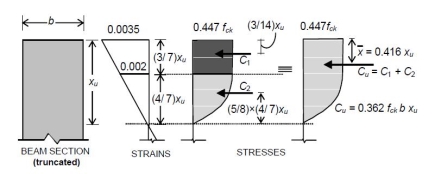
Analysis of a given reinforced concrete section at the ultimate limit state of flexure implies the determination of the ultimate moment MuR of resistance of the section. This is easily obtained from the couple resulting from the flexural stresses (Fig 1.9).


Where Cu and Tu are the resultant (ultimate) forces in compression and tension respectively, and z is the lever arm.

|
|
And the line of action of Tu corresponds to the level of the centroid of the tension steel.
Concrete Stress Block in Compression
In order to determine the magnitude of Cu and its line of action, it is necessary to analyse the concrete stress block in compression. As ultimate failure of a reinforced concrete beam inflexure occurs by the crushing of concrete, for both under- and over-reinforced beams, the shape of the compressive stress distribution (stress block) at failure will be, in both cases. The value of Cu can be computed knowing that the compressive stress in concrete is uniform at 0.447 fck for a depth of 3xu / 7, and below this it varies parabolically over a depth of 4xu / 7 to zero at the neutral axis.
Ultimate Moment of Resistance
Accordingly, in terms of the concrete compressive strength, |
M uR = 0.361 f ck bxu(d*0.416 xu) for all xu |
Alternatively, in terms of the steel tensile stress, |
M uR= f stAst(d*0.416 xu) for all xu |
With fst=0.87fy for xu=xu,max |

Case-1: | xu | Equal to the limiting value | xu,max | : Balanced section. |
| d |
| d | |
Case-2: | xu | Less than limiting value: under-reinforced section. | ||
d | ||||
|
|
|
| |
Case-3: | xu | More than limiting value: over-reinforced section. | ||
d | ||||
|
|
|
| |
In balanced section, the strain in steel and strain in concrete reach their maximum values simultaneously. The percentage of steel in this section is known as critical or limiting steel percentage. The depth of neutral axis (NA) is xuxu,max .
Under-reinforced section
An under-reinforced section is the one in which steel percentage (pt) is less than critical or limiting percentage ( pt,lim ). Due to this the actual NA is above the balanced NA and
xuxu,max.
Over-reinforced section
In the over reinforced section the steel percentage is more than limiting percentage due to which NA falls below the balanced NA and xuxu,max . Because of higher percentage of steel, yield does not take place in steel and failure occurs when the strain in extreme fibres in concrete reaches its ultimate value.
The designer has to make preliminary plan lay out including location of the beam, its span and spacing, estimate the imposed and other loads from the given functional requirement of the structure. The dead loads of the beam are estimated assuming the dimensions b and d initially. The bending moment, shear force and axial thrust are determined after estimating the different loads. In this illustrative problem, let us assume that the imposed and other loads are given. Therefore, the problem is such that the designer has to start with some initial dimensions and subsequently revise them, if needed. The following guidelines are helpful to assume the design parameters initially.
Selection of breadth of the beam b
Normally, the breadth of the beam b is governed by: (i) proper housing of reinforcing bars and (ii) architectural considerations. It is desirable that the width of the beam should be less than or equal to the width of its supporting structure like column width, or width of the wall etc. Practical aspects should also be kept in mind. It has been found that most of the requirements are satisfied with b as 150, 200, 230, 250 and 300 mm. Again, width to overall depth ratio is normally kept between 0.5 and 0.67.
Selection of depths of the beam d and D
The effective depth has the major role to play in satisfying (i) the strength requirements of bending moment and shear force, and (ii) deflection of the beam. The initial effective depth of the beam, however, is assumed to satisfy the deflection requirement depending on the span and type of the reinforcement. IS 456 stipulates the basic ratios of span to effective depth of beams for span up to 10 m as (Clause 23.2.1)
Cantilever - 7
Simply supported - 20
Continuous - 26
For spans above 10 m, the above values may be multiplied with 10/span in metres, except for cantilevers where the deflection calculations should be made. Further, these ratios are to bemultiplied with the modification factor depending on reinforcement percentage and type. Figures 4 and 5 of IS 456 give the different values of modification factors. The total depth D can be determined by adding 40 to 80 mm to the effective depth
Selection of the amount of steel reinforcement Ast
The amount of steel reinforcement should provide the required tensile force T to resist the factored moment Mu of the beam. Further, it should satisfy the minimum and maximum percentages of reinforcement requirements also. The minimum
Reinforcement As is provided for creep, shrinkage, thermal and other environmental requirements irrespective of the strength requirement.

|
|
|
|
The maximum tension reinforcement should not exceed 0.04 bD (cl. 26.5.1.1b of IS 456), where D is the total depth.
Selection of diameters of bar of tension reinforcement
Reinforcement bars are available in different diameters such as 6, 8, 10, 12, 14, 16, 18, 20, 22, 25, 28, 30, 32, 36 and 40 mm. Some of these bars are less available. The selection of the diameter of bars depends on its availability, minimum stiffness to resist while persons walk over them during construction, bond requirement etc. Normally, the diameters of main tensile bars are chosen from 12, 16, 20, 22, 25 and 32 mm.
Selection of grade of concrete
Besides strength and deflection, durability is a major factor to decide on the grade of concrete. Table 5 of IS 456 recommends M 20 as the minimum grade under mild environmental exposure and other grades of concrete under different environmental exposures also.
Selection of grade of steel
Normally, Fe 250, 415 and 500 are in used in reinforced concrete work. Mild steel (Fe 250) is more ductile and is preferred for structures in earthquake zones or where there are possibilities of vibration, impact, blast etc.
Failure Modes due to Shear

Web shear progress along dotted lines

Flexural tension

Flexural compression
Bending in reinforced concrete beams is usually accompanied by shear, the exact analysis of which is very complex. However, experimental studies confirmed the following three different modes of failure due to possible combinations of shear force and bending moment at a given section:
(i) Web shear
(ii) Flexural tension shear
(iii) Flexural compression shear
Web shear causes cracks which progress along the dotted line shown in Fig. 1.10a. Steel yields in flexural tension shear as shown in Fig. 1.10b, while concrete crushes in compression due to flexural compression shear as shown in Fig. 1.10c. An in-depth presentation of the three types of failure modes is beyond the scope here. Only the salient points needed for the routine design of beams in shear are presented here.
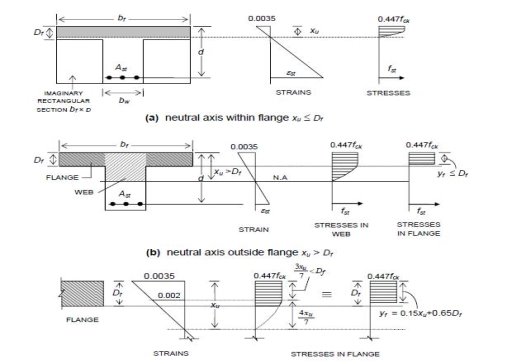
The procedure for analyzing flanged beams at ultimate loads depends on whether the neutral axis is located in the flange region or in the web region.
If the neutral axis lies within the flange (i.e., xu ≤ Df ), then as in the analysis at service loads all the concrete on the tension side of the neutral axis is assumed ineffective, and the T-section may be analyzed as a rectangular section of width bf and effective depth d.
If the neutral axis lies in the web region (i.e., xu>Df ), then the compressive stress is carried by the concrete in the flange and a portion of the web, as shown in Fig. 2.8(b). It is convenient to consider the contributions to the resultant compressive force Cu , from the web portion (bw × xu) and the flange portion (width bf−bw) separately, and to sum up these effects. Estimating the compressive force Cuw in the web and its moment contribution Muw is easy, as the full stress block is operative.


Design Procedure
In the case of a continuous flanged beam, the negative moment at the face of the support generally exceeds the maximum positive moment (at or near the midspan), and hence governs the proportioning of the beam cross-section. In such cases of negative moment, if the slab is located on top of the beam (as is usually the case) the flange is under flexural tension and hence the concrete in the flange is rendered ineffective. The beam section at the support is therefore to be designed as a rectangular section for the factored negative moment. Towards the mid span of the beam, however, the beam behaves as a proper flanged beam (with the flange under flexural compression).
The determination of the actual reinforcement in a flanged beam depends on the location of the neutral axis xu, which, of course, should be limited to xu,max. If Mu exceeds Mu,lim for a singly reinforced flange section, the depth of the section should be suitably increased; otherwise, a doubly reinforced section is to be designed.
Neutral Axis within Flange (xu≤Df):
This is, by far, the most common situation encountered in building design. Because of the very large compressive concrete area contributed by the flange in T-beam and L-beams of usual proportions, the neutral axis lies within the flange (xu ≤ Df),
Whereby the section behaves like a rectangular section having width bf and effective depth d.
Neutral Axis within Web (xu>Df):
When


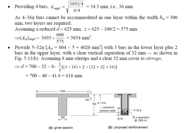
A continuous T-beam has the cross-sectional dimensions shown in figure below. The web dimensions have been determined from the consideration of negative moment at support and shear strength requirements. The span is 10 m and the design moment at mid span under factored loads is 800 kNm. Determine the flexural reinforcement requirement at mid span. Consider Fe 415 steel. Assume that the beam is subjected to moderate exposure conditions.
Determining approximate Ast
Effective flange width bf
Actual flange width provided =1500mm; Df=100 mm; bw=300mm
Maximum width permitted =(0.7x10000)/6 + 300 + (6x100) =2067 mm >1500 mm Therefore, bf =1500 mm
Assuming d=650 mm and a lever arm z equal to larger of 0.9d = 585 mm And d- Df/2 = 600mm i.e. z=600 mm

Determining actual Ast
xu,max= 0.479 × 618 =296 mm
As xu,max>Df=100mm, the condition xu=Df satisfies xuxu,max
• Assuming M 25 concrete, fck = 25 MPa
( MuR )xuDf 0.362 × 25 × 1500 × 100 × (618 – 0.416 × 100)
6
= 782.5 × 10 Nmm<Mu = 800 kNm
WhereCuw = 0.362fckbw u = 0.362 × 25 × 300xu = (2715xu) N
AndCuf = 0.447fck (bf – bw)yf = 0.447 × 25 × (1500 – 300)yf = (13410yf) Considering xu = 7Df /3 = 233 mm ( <xu,max = 296 mm), yf = Df = 100 mm
Cuf= 13410(0.15x.65 × 100) = (2011.5xu+ 871650) N Mu= 800 × 106= (2715xu)(618–0.416xu)

+ (2011.5xu+871650)x[618-(0.15xu+65)/2]
= -1280.3xu2+ 2790229.5xu+ 510.35×10⁶
Solving this quadratic equation,
xu= 109.3 mm<xu,max= 296 m
The reinforcement (5-32Φ; Ast=4020 mm2, based on appropriate estimate of Ast is evidently adequate and appropriate.
Reference Books:
- RCC Design and drawing By Neelam Sharma
- Limit state design of reinforced concrete by P.C. Verghese, PHI
- Reinforced concrete: Limit state by A.K. Jain
- Reinforced concrete by B.C. Punamia, A.K. Jain and A.K. Jain
- IS Code 456:2000