Module – 5
Limit state of collapse in shear
Limit states are the acceptable limits for the safety and serviceability requirements of the structure before failure occurs. The design of structures by this method will thus ensure that they will not reach limit states and will not become unfit for the use for which they are intended.
Limit state are two types
- Limit state of collapse
- Limit state of serviceability.
Limit states of collapse
The limit state of collapse of the structure or part of the structure could be assessed from rupture of one or more critical sections and from bucking due to elastic bending, shear, torsion and axial loads at every section shall not be less than the appropriate value at that section produced by the probable most unfavorable combination of loads on the structure using the appropriate factor of safely.
Recent laboratory experiments confirmed that reinforced concrete in beams has shear strength even without any shear reinforcement. This shear strength (τ ) depends on the grade of concrete and the percentage of tension steel in beams. On the other hand, the shear strength of reinforced concrete with the reinforcement is restricted to some maximum value τ depending on the grade of concrete. These minimum and maximum shear strengths of reinforced concrete (IS 456, cls. 40.2.1 and 40.2.3, respectively) are given by IS code.
Shear Stress:
The distribution of shear stress in reinforced concrete rectangular, T and L-beams of uniform and varying depths depends on the distribution of the normal stress. However, for the sake of simplicity the nominal shear stress τv is considered which is calculated as follows (IS 456, cls.40.1 and 40.1.1):
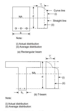
Distribution of shear stress and average shear stress In beams of uniform depth :

Where Vu= shear force due to design loads,
b = breadth of rectangular beams and breadth of the webb for flanged beams,
d = effective depth.
(ii) In beams of varying depth:

Whereηv, Vu, b or bw and d are the same as in (i),
Mu = bending moment at the section, and
β = angle between the top and the bottom edges.
Design Shear Strength of Reinforced Concrete
Recent laboratory experiments confirmed that reinforced concrete in beams has shear strength even without any shear reinforcement. This shear strength (τ ) depends on the grade of concrete and the percentage of tension steel in beams. On the other hand, the shear strength of reinforced concrete with the reinforcement is restricted to some maximum valueτ depending on the grade of concrete. These minimum and maximum shear strengths of reinforced concrete (IS 456, cls. 40.2.1 and 40.2.3, respectively) are given below:
Design shear strength without shear reinforcement (IS 456, cl. 40.2.1)
Table 19 of IS 456 stipulates the design shear strength of concrete τc for different grades of concrete with a wide range of percentages of positive tensile steel reinforcement. It is worth mentioning that the reinforced concrete beams must be provided with the minimum shear reinforcement as per cl. 40.3 even when τv is less than τc given in Table 3.
2
Table 3 Design shear strength of concrete, τc in N/mm
100 As / bd |
|
| Grade of concrete |
|
| ||
M 20 | M 25 |
| M 30 |
| M 35 | M40 and | |
|
|
| |||||
|
|
|
|
|
|
| Above |
≤ 0.15 | 0.28 | 0.29 |
| 0.29 |
| 0.29 | 0.30 |
0.25 | 0.36 | 0.36 |
| 0.37 |
| 0.37 | 0.38 |
0.50 | 0.48 | 0.49 |
| 0.50 |
| 0.50 | 0.51 |
0.75 | 0.56 | 0.57 |
| 0.59 |
| 0.59 | 0.60 |
1.00 | 0.62 | 0.64 | 0.66 | 0.67 | 0.68 | ||
1.25 | 0.67 | 0.70 | 0.71 | 0.73 | 0.74 | ||
1.50 | 0.72 | 0.74 | 0.76 | 0.78 | 0.79 | ||
1.75 | 0.75 | 0.78 | 0.80 | 0.82 | 0.84 | ||
2.00 | 0.79 | 0.82 | 0.84 | 0.86 | 0.88 | ||
2.25 | 0.81 | 0.85 | 0.88 | 0.90 | 0.92 | ||
2.50 | 0.82 | 0.88 | 0.91 | 0.93 | 0.95 | ||
2.75 | 0.82 | 0.90 | 0.94 | 0.96 | 0.98 | ||
≥ 3.00 | 0.82 | 0.92 | 0.96 | 0.99 | 1.01 | ||
In Table 3, As is the area of longitudinal tension reinforcement which continues at least one effective depth beyond the section considered except at support where the full area of tension reinforcement may be used provided the detailing is as per IS 456, cls. 26.2.2 and 26.2.3.
Maximum shear stress τcmax with shear reinforcement (cls. 40.2.3, 40.5.1 and 41.3.1)
Table 20 of IS 456 stipulates the maximum shear stress of reinforced concrete in beams τcmax as given below in Table 6.2. Under no circumstances, the nominal shear stress in beams τv shall exceed τcmax given in Table 6.2 for different grades of concrete.
Table 4 Maximum shear stress, τ | In N/mm | 2 |
|
|
| ||
|
|
|
| ||||
|
|
| Cmax |
|
|
|
|
|
|
|
|
|
|
|
|
Grade of | M 20 |
| M 25 |
| M 30 | M 35 | M 40 and |
Concrete |
|
|
|
|
|
| Above |
c,max N/mm2 | 2.8 |
| 3.1 |
| 3.5 | 3.7 | 4.0 |
|
|
|
|
|
|
|
|
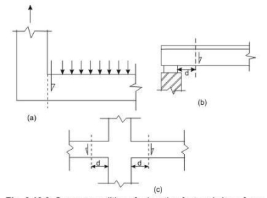
Support condition for
Locating factored shear force
Clauses 22.6.2 and 22.6.2.1 stipulate the critical section for shear and are as follows:
For beams generally subjected to uniformly distributed loads or where the principal load is located further than 2d from the face of the support, where d is the effective depth of the beam, the critical sections depend on the conditions of supports as shown in Figs. 1.12 a, b and c and are mentioned below.
(i) When the reaction in the direction of the applied shear introduces tension (Fig. 1.12a) into the end region of the member, the shear force is to be computed at the face of the support of the member at that section.
(ii) When the reaction in the direction of the applied shear introduces compression into the end region of the member (Figs. 1.12b and c), the shear force computed at a distance d from the face of the support is to be used for the design of sections located at a distance less than d
From the face of the support. The enhanced shear strength of sections close to supports, however, may be considered as discussed in the following section.
Minimum Shear Reinforcement (cls. 40.3, 26.5.1.5 and 26.5.1.6 of IS 456)
Minimum shear reinforcement has to be provided even when τv is less than τc given in Table 3 as recommended in cl. 40.3 of IS 456. The amount of minimum shear reinforcement, as given in cl. 26.5.1.6, is given below.
The minimum shear reinforcement in the form of stirrups shall be provided such that:

|
|
|
|
|
|
|
|
| |||
|
|
| |||
WhereAsv = total cross-sectional area of stirrup legs effective in shear, sv= stirrup spacing along the length of the member,
b = breadth of the beam or breadth of the web of the web of flanged beambw, and
2
fy= characteristic strength of the stirrup reinforcement in N/mm which shall not be
2
Taken greater than 415 N/mm .
The above provision is not applicable for members of minor structural importance such as lintels where the maximum shear stress calculated is less than half the permissible value.
(iii) Tension failure is prevented which would have occurred due to shrinkage, thermal stresses and internal cracking in beams.
(iv) To hold the reinforcement in place when concrete is poured.
(v) Section becomes effective with the tie effect of the compression steel.
Further, cl. 26.5.1.5 of IS 456 stipulates that the maximum spacing of shear reinforcement measured along the axis of the member shall not be more than 0.75 d for vertical stirrups.
When τv is more than τc given in Table 6.1, shear reinforcement shall be provided in any of the three following forms:
(a) Vertical stirrups,
(b) Bent-up bars along with stirrups, and
(c) Inclined stirrups.
In the case of bent-up bars, it is to be seen that the contribution towards shear resistance of bent-up bars should not be more than fifty per cent of that of the total shear reinforcement.

|
|
Where b is the breadth of rectangular beams or bw in the case of flanged beams. |
|
The strengths of shear reinforcement Vus for the three types of shear reinforcement are as follows:
(a) Vertical stirrups:

|
|
|
|
| |
(b) For inclined stirrups or a series of bars bent-up at different cross-sections:

|
|
|
|
(c) For single bar or single group of parallel bars, all bent-up at the same cross-section:

Where Asv = total cross-sectional area of stirrup legs or bent-up bars within a distance sv, sv= spacing of stirrups or bent-up bars along the length of the member, ηv = nominal shear stress,
ηc = design shear strength of concrete,
b = breadth of the member which for the flanged beams shall be taken as the breadth of the web bw,
Curtailment of Tension Reinforcement in Flexural Members (cl. 26.2.3.2 of IS 456)
Curtailment of tension reinforcement is done to provide the required reduced area of steel with the reduction of the bending moment. However, shear force increases with the reduction of bending moment. Therefore, it is necessary to satisfy any one of following three conditions while terminating the flexural reinforcement in tension zone:
(i) The shear stress ηv at the cut-off point should not exceed two-thirds of the permitted value
Which includes the shear strength of the web reinforcement. Accordingly,


(ii) For each of the terminated bars, additional stirrup area should be provided over a distance of three-fourth of effective depth from the cut-off point. The additional stirrup area shall not be less than 0.4 b s/fy, where b is the breadth of rectangular beams and is replaced by bw


(iii) For bars of diameters 36 mm and smaller, the continuing bars provide double the area required for flexure at the cut-off point. The shear stress should not exceed three-fourths that permitted. Accordingly,
In the above expression b is the breadth of the rectangular beams which will be bw in the case of flanged beams.
The bond between steel and concrete is very important and essential so that they can act together without any slip in a loaded structure. With the perfect bond between them, the plane section of a beam remains plane even after bending. The length of a member required to develop the full bond is called the anchorage length. The bond is measured by bond stress. The local bond stress varies along a member with the variation of bending moment.
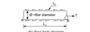
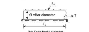
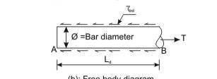 Accordingly, IS 456, cl. 26.2 stipulates the requirements of proper anchorage of reinforcement in terms of development length Ld only employing design bond stress ηbd.
Design bond stress – values
The average bond stress is still used in the working stress method and IS 456 has mentioned about it in cl. B-2.1.2. However, in the limit state method of design, the average bond stress has been designated as design bond stress ηbd and the values are given in cl. 26.2.1.1. The same is given below as a ready reference.
Table 5: η for plain bars in tension
Bd
Grade of concrete | M 20 | M 25 | M 30 | M 35 | M 40 and |
|
|
|
|
| Above |
Design Bond Stress | 1.2 | 1.4 | 1.5 | 1.7 | 1.9 |
τbd in N/mm2 |
|
|
|
|
|
|
|
|
|
|
|
For deformed bars conforming to IS 1786, these values shall be increased by 60 per cent. For bars in compression, the values of bond stress in tension shall be increased by 25 percent.
Development Length
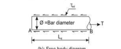
Development length of bar
At least one-third of the positive moment reinforcement in simple members and one-fourth of the positive moment reinforcement in continuous members shall be extended along the same face of the member into the support, to a length equal to Ld/3
Types of shear reinforcement:
The following three types of shear reinforcement are used:
- Vertical stirrups.
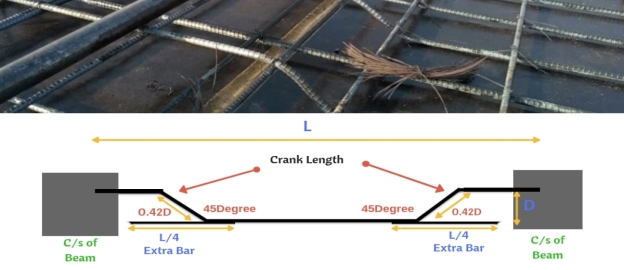
- Bent up bars along with stirrups.
- Inclined stirrups.
In the case of bent-up bars, it is to be seen that the contribution towards shear resistance of bent-up bars should not be more than fifty per cent of that of the total shear reinforcement.
 5.5 SLAB:
Slab is a two-dimensional or planar element, used in all types of structures such as floors and roof coverings. The thickness of slab is very small as compared to its length and width.
Slabs are classified on the basis of ratio into following two types:
(i) One way slab
(ii) Two way slab.
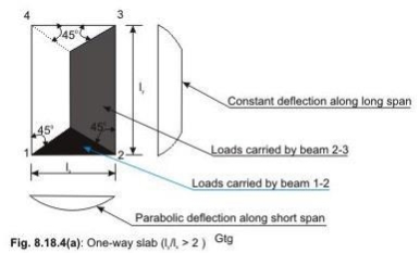
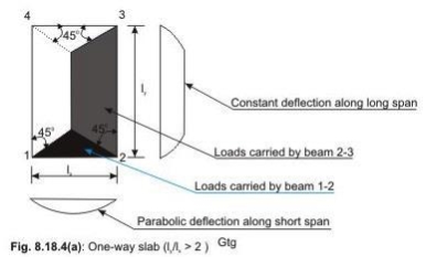
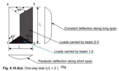
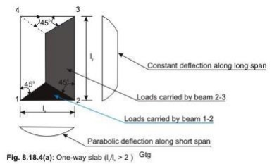
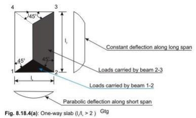
One Way Slab One way slabs are those slabs in which the ratio is greater than 2. This type of slab is also called as slab spanning in one direction, as the bending takes place only along the shorter span. Therefore, the main reinforcement is provided along the shorter span. The one way slab is analyzed by assuming it to be a beam of 1 m width.
Two-way slabs subjected mostly to uniformly distributed loads resist them primarily by bending about both the axis. However, as in the one-way slab, the depth of the two-way slabs should also be checked for the shear stresses to avoid any reinforcement for shear. Moreover, these slabs should have sufficient depth for the control deflection. Thus, strength and deflection are the requirements of design of two-way slabs.
There are two kinds of two way slabs:
(1) Restrained Slabs: When a two way slab is loaded, the corners get lifted up. These corners can be prevented from lifting by providing fixidity at the supports by beams or walls. Such type of slabs in which the corners are prevented from lifting are called as restrained slabs. In these slabs special torsion reinforcement is provided at the edges to prevent cracking of the corners. These are also called as slabs with corners held down.
(2) Unrestrained Slabs: The slabs in which corners are not prevented from lifting.
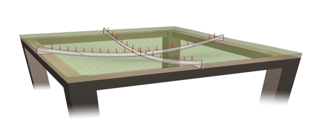
CONTINUOUS SLABS: The beams and slabs are cast monolithic in reinforced concrete construction. The T beams are in aced at regular intervals and the slab is continuous over these supports. The design of such one-way continuous slab can be done by the moment and shear coefficients method given in IS 456:2000.
These coefficients give the moment and shear force values at the critical sections. These coefficients are applicable only if: The slab is continuous over three or more spans which do not differ by more than 15 percent of the longest spans and loads are mainly uniformly distributed. It is to be noted that redistribution of moments is not permitted when moments are determined using moment coefficients.
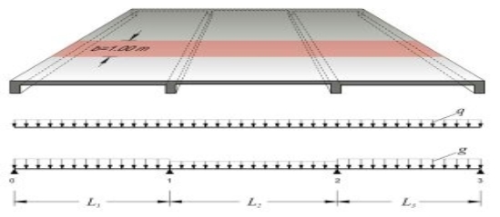
One way slab is designed exactly as a rectangular beam (given in chapter), the only difference are following:
- The width of the beam is assumed as one meter,
- The depth of slab can be assumed on the basis of control of deflection.
- Using balanced percentage of steel the ratios are modified.
- To start with the span to depth ratios are approximated as following for initial depth trial calculations.
(1) For simply supported slabs, 25 to 30
(2) For cantilever slabs 10
In addition to the main tensile reinforcement provided along shorter span, transverse reinforcement or distribution reinforcement is provided
Some of the main bars in a slab are bent up near the supports. Shear is to be checked only. No shear reinforcement is provided.
Design Steps:
The procedure of the design of one-way slab is the same as that of beams. The different steps of the design are explained below.
Step 1: depth of Selection of preliminary slab
The depth of the slab shall be assumed from the span to effective depth ratios.
Step 2: Design loads, bending moments and shear forces
The total factored (design) loads are to be determined adding the estimated dead load of the slab, load of the floor finish, given or assumed live loads etc. after multiplying each of them with the respective partial safety factors. Thereafter, the design positive and negative bending moments and shear forces are to be determined using the respective coefficients given in Tables 12 and 13 of IS 456.
Step 3:. Determination/checking of the effective and total depths of slabs The effective depth of the slab shall be determined employing.
Step 4: Depth of the for shear force slab
Theoretically, the depth of the slab can be checked for shear force if the design shear strength of concrete is known. Since this depends upon the percentage of tensile reinforcement, the design shear strength shall be assumed considering the lowest percentage of steel. The value ofcshall be modified after knowing the multiplying factor k from the depth tentatively selected for the slab in Step 3. If necessary, the depth of the slab shall be modified.
Step 5: Determination of areas of steel
Area of steel reinforcement along the direction of one-way slab should be determined employing the following Eq.

The above equation is applicable as the slab in most of the cases is under-reinforced due to the selection of depth larger than the computed value in Step 3. The area of steel so determined should be checked whether it is at least the minimum area of steel as mentioned in cl.26.5.2.1 of IS 456.
Step 6: Selection of diameters and spacings of reinforcing bars (cls.26.5.2.2 and 26.3.3 of IS 456)
The diameter and spacing of bars are to be determined as per cls.26.5.2.2 and 26.3.3 of IS
456. As mentioned in Step 5, this step may be avoided when using the tables and charts of SP-16.Design the one-way continuous slab of Fig.8.18.6 subjected to uniformly distributed imposed
2 2
Loads of 5 kN/m using M 20 and Fe 415. The load of floor finish is 1 kN/m . The span dimensions shown in the figure are effective spans. The width of beams at the support = 300 mm.

Two-way Slabs
Two-way slabs subjected mostly to uniformly distributed loads resist them primarily by bending about both the axis. However, as in the one-way slab, the depth of the two-way slabs should also be checked for the shear stresses to avoid any reinforcement for shear. Moreover, these slabs should have sufficient depth for the control deflection. Thus, strength and deflection are the requirements of design of two-way slabs.
Computation of shear force
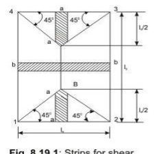
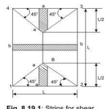
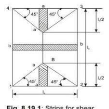
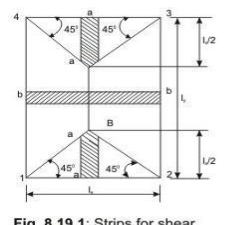
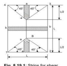
Shear forces are computed following the procedure stated below with reference to Fig.2.2.
The two-way slab of Fig. 2.2 is divided into two trapezoidal and two triangular zones by
o
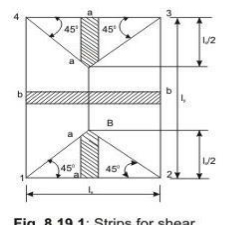
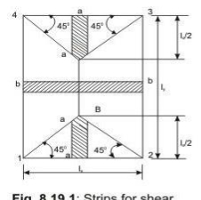
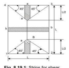
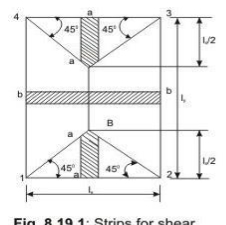
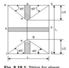 drawing lines from each corner at an angle of 45 . The loads of triangular segment A will be transferred to beam 1-2 and the same of trapezoidal segment B will be beam 2-3. The shear forces per unit width of the strips aa and bb are highest at the ends of strips. Moreover, the length of half the strip bb is equal to the length of the strip aa. Thus, the shear forces in both strips are equal and we can write
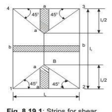 Vu = W (lx/2)
Computation of bending moments
Two-way slabs spanning in two directions at right angles and carrying uniformly distributed loads may be analysed using any acceptable theory. Pigeoud ‘s or Wester-guard‘s theories are the suggested elastic methods and Johansen‘s yield line theory is the most commonly used in the limit state of collapse method and suggested by IS 456 in the note of cl. 24.4. Alternatively, Annex D of IS 456 can be employed to determine the bending moments in the two directions for two types of slabs: (i) restrained slabs, and (ii) simply supported slabs. The two methods are explained below:
(i) Restrained slabs
Restrained slabs are those whose corners are prevented from lifting due to effects of torsional moments. These torsional moments, however, are not computed as the amounts of reinforcement are determined from the computed areas of steel due to positive bending moments depending upon the intensity of torsional moments of different corners. Thus, it is essential to determine the positive and negative bending moments in the two directions of restrained slabs depending on the various types of panels and the aspect ratio ly/lx.
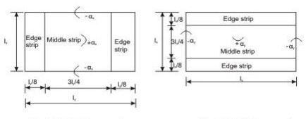
For Span lx For Span ly
Restrained slabs are considered as divided into two types of strips in each direction: (i) one middle strip of width equal to three-quarters of the respective length of span in either directions, and (ii) two edge strips, each of width equal to one-eighth of the respective length of span in either directions.
(ii) Simply supported slabs
The maximum moments per unit width of simply supported slabs not having adequate provision to resist torsion at corners and to prevent the corners from lifting.
Detailing of Reinforcement
The detailing of reinforcing bars for (i) restrained slabs and (ii) simply supported slabs are discussed separately for the bars either for the maximum positive or negative bending moments or to satisfy the requirement of minimum amount of steel.
(i) Restrained slabs
The maximum positive and negative moments per unit width of the slab calculate dare applicable only to the respective middle strips. There shall be no redistribution of these moments.
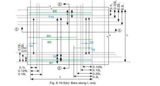
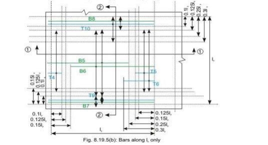
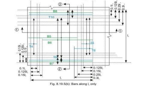
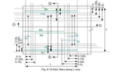
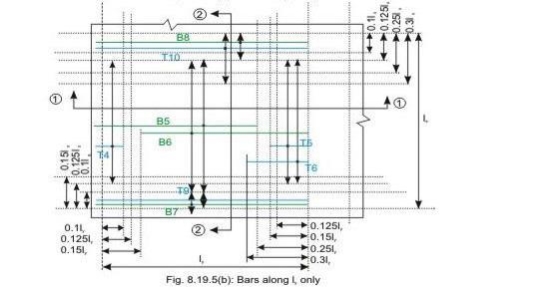
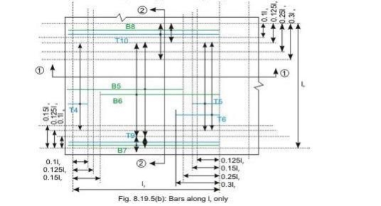
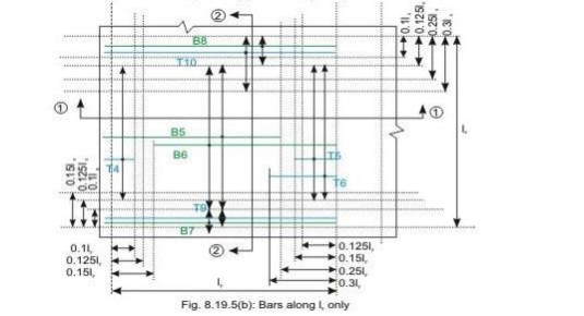
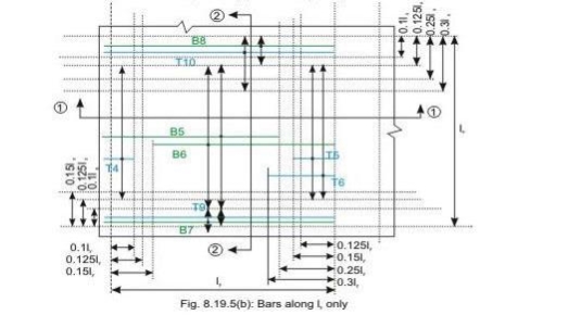
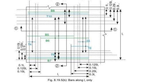
Bars along lx only
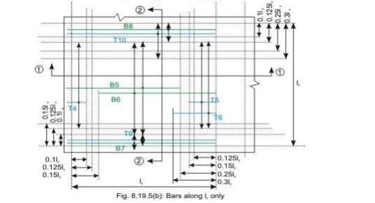
 Bars along ly only
Reinforcement of two-way slab
(except torsion reinforcement)
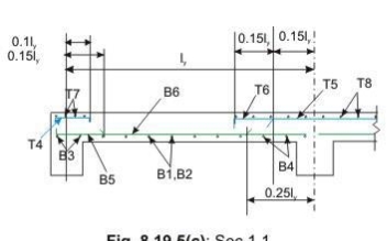
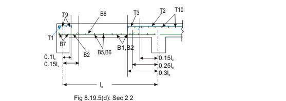
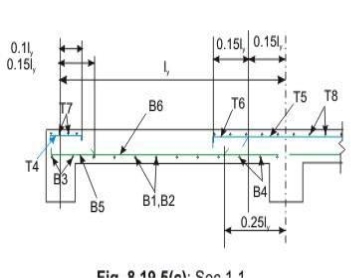
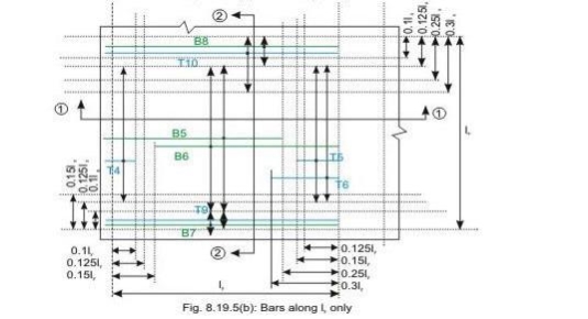
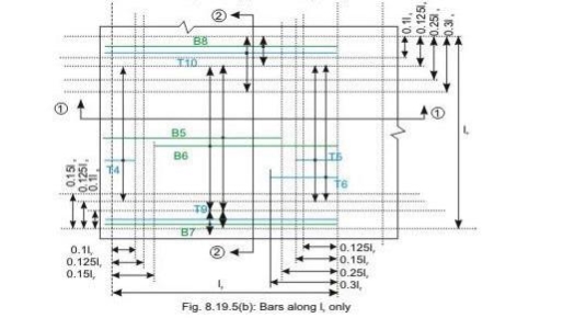
Bottom tension reinforcement bars of mid-span in the middle strip shall extent in the lower part of the slab to within 0.25l of a continuous edge, or 0.15l of a
Discontinuous edge (cl. D-1.4 of IS 456). Bars marked as B1, B2, B5 and B6 in Figs 8.19a and b are these bars.
• Top tension reinforcement bars over the continuous edges of middle strip shall extend in the upper part of the slab for a distance of 0.15l from the support, and at least fifty per cent of these bars shall extend a distance of 0.3l (cl. D-1.5 of IS 456). Bars marked as T2, T3, T5 and T6 in Figs.8.19.5 a and b are these bars.
• To resist the negative moment at a discontinuous edge depending on the degree of fixity at the edge of the slab, top tension reinforcement bars equal to fifty per cent of that provided at mid-span shall extend 0.1l into the span (cl. D-1.6 of IS 456). Bars marked as T1 and T4 in Figs.8.19a and b are these bars.
• The edge strip of each panel shall have reinforcing bars parallel to that edge satisfying the requirement of minimum reinforcement. The bottom and top bars of the edge strips are explained below.
• Bottom bars B3 and B4 are parallel to the edge along lx for the edge strip for span ly, satisfying the requirement of minimum amount of steel (cl. D-1.7 of IS 456).
• Bottom bars B7 and B8 are parallel to the edge along ly for the edge strip for span lx, satisfying the requirement of minimum amount of steel (cl. D-1.7 of IS 456).
• Top bars T7 and T8 are parallel to the edge along lx for the edge strip for span ly, satisfying the requirement of minimum amount of steel (cl. D-1.7 of IS 456).
• Top bars T9 and T10 are parallel to the edge along ly for the edge strip for span lx, satisfying the requirement of minimum amount of steel (cl. D-1.7 of IS 456).
Numerical Problem for practice:
Design a R.C. Slab for a room measuring 5mx6m size. The slab is simply supported on all the four edges, with corners held down and carries a super-imposed load of 3 KN/m2 inclusive of floor finish etc. Use M20 grade of concrete and Fe 415 grade of steel.
The various loads coming on a slab are as follows:
- Self weight (dead load) of the slab
- Live loads as per use.
- Finishing and partitioned loads. These Loads can be taken from IS code 875 (Part-I)
 Dead Loads
 Dead loads are due to self weight of the structure. These are the permanent loads which are always present. Dead load depends upon the unit weight of the material. Dead load includes the self-weight of alls. Beams, columns etc. and also the permanent fixtures present in the unit weights of commonly used building materials are given in the code IS 875 (part-f)- 1987.
- Live Loads
Live loads on floors and roofs consists of all the loads which are temporarily placed on the structure, For example, loads of people, furniture, machines etc. These loads keep on changing from time to time. They are also called as imposed loads. Various types of imposed loads coming the structure given in IS 875 (Part-2): 1987. The imposed loads depend upon the use of building.
- Wind Loads
The force exerted by the horizontal component of wind is to be considered in the design of buildings. It depends upon the velocity of wind, shape and size of the building. The method of calculating wind load on structure is given in IS 875 (Part-3): 1987..
- Snow Loads
The buildings which are located in the regions where snowfall is very common, are to be designed for snow load. The code IS 875 (Part-4): 1987 deals with snow load on roofs of the building.
- Earthquake Loads
Earthquake loads depend upon the place where the building is located. As per 1893-2002 (Part-I) (General Provisions for Buildings), India is divided into four seismic zones. The code gives recommendations for earthquake resistant design of structures. Now, it is mandatory to follow these recommendations for design of structures.
Reference Books:
- RCC Design and drawing By Neelam Sharma
- Limit state design of reinforced concrete by P.C. Verghese, PHI
- Reinforced concrete: Limit state by A.K. Jain
- Reinforced concrete by B.C. Punamia, A.K. Jain and A.K. Jain
- IS Code 456:2000