MODULE – 6
Classification of column
Compression members are structural elements primarily subjected to axial compressive forces and hence, their design is guided by considerations of strength and buckling. Examples of compression member pedestal, column, wall and strut.
Column is an important element of every reinforced concrete structure. These are used to transfer the load of superstructure to the foundation safely.
A column is defined as a vertical compression member which is mainly subjected to axial Loads and the effective length of which exceeds three times its least lateral dimension. The compression member whose effective length is less than three times its least lateral dimension is called as Pedestal. The compression member which is inclined or horizontal and is subjected to axial loads is called as Strut. Struts are used in trusses.
Columns are classified based on different criteria such as:
- Shapes of cross-section.
- Material of construction.
- Type of loading.
- Slenderness ratio.
- Type of lateral reinforcement.
Classification Based on Slenderness ratio
The slenderest ratio of a compression member is defined as the ratio of effective length to the lateral dimension.
The columns are classified as following two types depending upon the slenderness
- Short columns
- Long columns
Short Column: The column is considered as short when the slenderness ratio of column i.e., ratio of effective length to its least lateral dimension is less than or equal to 12.
Long Column: If the slenderness ratio of the column is greater than 12 , it is called as long or slender column
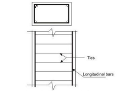 Classification Based on Loadings
(1) Axially loaded columns.
(2) Eccentrically loaded columns.
- Axially loaded column: The columns which are subjected to loads acting along the longitude axis or centroid of the column section are called as axially loaded columns. Axially loaded column is subjected to direct compressive stress only and no bending stress develops anywhere in the column section.
- Eccentrically loaded columns: Eccentrically loaded columns are those columns in when loads do not act on the longitudinal axis of the column. They are subjected to direct compress stress and bending stress both.
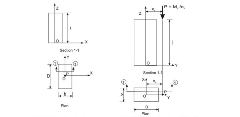
Coaxial loading (concentric) Axial loading with uniaxial bending
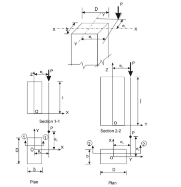
Axial loading with biaxial bending
Longitudinal Reinforcement
The longitudinal reinforcing bars carry the compressive loads along with the concrete. Clause 26.5.3.1 stipulates the guidelines regarding the minimum and maximum amount, number of bars, minimum diameter of bars, spacing of bars etc
Transverse Reinforcement
Transverse reinforcing bars are provided in forms of circular rings, polygonal links or helical reinforcement. The transverse reinforcing bars are provided to ensure that every longitudinal bar nearest to the compression face has effective lateral support against buckling. Clause 26.5.3.2 stipulates the guidelines of the arrangement of transverse reinforcement. The salient points are:
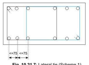
Pitch and Diameter of Lateral Ties
(a) Pitch: The maximum pitch of transverse reinforcement shall be the least of the following:
- The least lateral dimension of the compression members
- Sixteen times the smallest diameter of the longitudinal reinforcement bar to be tied
- 300 mm.
Diameter: The diameter of the polygonal links or lateral ties shall be not less than one-fourth of the diameter of the largest longitudinal bar, and in no case less than 6 mm
The following are the assumptions in addition for flexure for the design of compression members (cl. 39.1 of IS 456).
- The maximum compressive strain in concrete in axial compression is taken as 0.002.
- The maximum compressive strain at the highly compressed extreme fiber in concrete subjected to axial compression and bending and when there is no tension on the section shall be 0.0035 minus 0.75 times the strain at the least compressed extreme fiber.
Minimum Eccentricity
All axially loaded columns should be designed considering the minimum eccentricity as stipulated in cl. 25.4 of IS 456
ex min≥greater of (l/500 + D/30) or 20 mm
ey min≥greater of (l/500 + b/30) or 20 mm
Wherel, D and b are the unsupported length, larger lateral dimension and least lateral dimension, respectively.
Assuming the design
Strengths of concrete and steel are 0.4fck and 0.67fy, respectively, we can write
Pu= 0.4fck Ac+ 0.67fyAsc
Where Pu = factored axial load on the member,
fck= characteristic compressive strength of the concrete,
Ac= area of concrete,
fy= characteristic strength of the compression reinforcement,
Asc= area of longitudinal reinforcement for columns.
Asc=pAg/100
Ac=Ag(1– p/100)
So, we can write
Pu/Ag= 0.4fck+ (p/100) (0.67fy–0.4fck)
Numerical Problem
Design the reinforcement in a column of size 400 mm x 600 mm subjected to an axial load of 2000 kN under service dead load and live load. The column has an unsupported length of 4.0 m and effectively held in position and restrained against rotation in both ends. Use M 25 concrete and Fe 415 steel.
Solution
Step 1: To check if the column is short or slender
Given l = 4000 mm, b = 400 mm and D = 600 mm. Table 28 of IS 456 = lex= ley = 0.65(l) = 2600 mm. So, we have
lex/D= 2600/600 = 4.33 < 12
ley/b= 2600/400 = 6.5 < 12
Hence, it is a short column.
Step 2: Minimum eccentricity
ex min= Greater of (lex/500 + D/30) and 20 mm = 25.2 mmey min= Greater of (ley/500 + b/30) and 20 mm = 20 mm
0.05 D = 0.05(600) = 30 mm > 25.2 mm (= ex min)
0.05 b = 0.05(400) = 20 mm = 20 mm (= ey min)
Hence, the equation given in cl.39.3 of IS 456 is applicable for the design here.
Step 3: Area of steel
Fro Eq.10.4, we have
Pu= 0.4fck Ac+ 0.67fyAsc
3
3000(10 ) = 0.4(25){(400)(600) – Asc} + 0.67(415) Asc which gives,
Asc= 2238.39 mm square
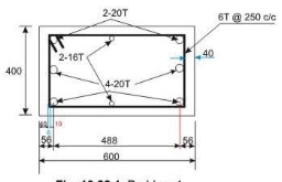
Provide 6-20 mm diameter and 2-16 mm diameter rods giving 2287 mm (> 2238.39 mm ) and p = 0.953 per cent, which is more than minimum percentage of 0.8 and less than maximum percentage of 4.0. Hence, o.k.
Step 4: Lateral ties
The diameter of transverse reinforcement (lateral ties) is determined from cl.26.5.3.2 C-2 of IS 456 as not less than (i) θ/4 and (ii) 6 mm. Here, θ = largest bar diameter used as longitudinal reinforcement = 20 mm. So, the diameter of bars used as lateral ties = 6 mm. The pitch of lateral ties, as per cl.26.5.3.2 C-1 of IS 456, should be not more than the least of
- The least lateral dimension of the column = 400 mm
- Sixteen times the smallest diameter of longitudinal reinforcement bar to be tied = 16(16) = 256 mm
- 300 mm
Reinforcement Detailing
Let us use p = pitch of lateral ties = 250 mm.
The superstructure is placed on the top of the foundation structure, designated as substructure as they are placed below the ground level. The elements of the superstructure transfer the loads and moments to its adjacent element below it and finally all loads and moments come to the foundation structure, which in turn, transfers them to the underlying soil or rock. Thus, the foundation structure effectively supports the superstructure. Accordingly, the major requirements of the design of foundation structures are the two as given below (see cl.34.1 of IS 456):
- Foundation structures should be able to sustain the applied loads, moments, forces and induced reactions without exceeding the safe bearing capacity of the soil.
2. The settlement of the structure should be as uniform as possible and it should be within the tolerable limits. It is well known from the structural analysis that differential settlement of supports causes additional moments in statically indeterminate structures.
Types of Foundation Structures
Shallow Foundation:
Shallow foundations are used when the soil has sufficient strength within a short depth below the ground level. They need sufficient plan area to transfer the heavy loads to the base soil. These heavy loads are sustained by the reinforced concrete columns or walls (either of bricks or reinforced concrete) of much less areas of cross-section due to high strength of bricks or reinforced concrete when compared to that of soil. The strength of the soil, expressed as the safe bearing capacity of the soil is normally supplied by the geotechnical experts to the structural engineer. Shallow foundations are also designated as footings. The different types of shallow foundations or footings are discussed below.
- Plain concrete pedestal footings
- Isolated footings
- Combined footings
- Strap footings
- Strip foundation or wall footings
- Raft or mat foundation
Deep foundations:
As mentioned earlier, the shallow foundations need more plan areas due to the low strength of soil compared to that of masonry or reinforced concrete. However, shallow foundations are selected when the soil has moderately good strength, except the raft foundation which is good in poor condition of soil also. Raft foundations are under the category of shallow foundation as they have comparatively shallow depth than that of deep foundation. It is worth mentioning that the depth of raft foundation is much larger than those of other types of shallow foundations
However, for poor condition of soil near to the surface, the bearing capacity is very less and foundation needed in such situation is the pile foundation. Piles are, in fact, small diameter columns which are driven or cast into the ground by suitable means. Precast piles are driven and cast-in-situ are cast. These piles support the structure by the skin friction between the pile surface and the surrounding soil and end bearing force, if such resistance is available to provide the bearing force. Accordingly, they are designated as frictional and end bearing piles. They are normally provided in a group with a pile cap at the top through which the loads of the superstructure are transferred to the piles.
Piles are very useful in marshy land where other types of foundation are impossible to construct. The length of the pile which is driven into the ground depends on the availability of hard soil/rock or the actual load test. Another advantage of the pile foundations is that they can resist uplift also in the same manner as they take the compression forces just by the skin friction in the opposite direction.
.
Minimum nominal cover (cl. 26.4.2.2 of IS 456)
The minimum nominal cover for the footings should be more than that of other structural elements of the superstructure as the footings are in direct contact with the soil. Clause 26.4.2.2 of IS 456 prescribes a minimum cover of 50 mm for footings. However, the actual cover may be even more depending on the presence of harmful chemicals or minerals, water table etc.
Thickness at the edge of footings (cls. 34.1.2 and 34.1.3 of IS 456)
The minimum thickness at the edge of reinforced and plain concrete footings shall be at least 150 mm for footings on soils and at least 300 mm above the top of piles for footings on piles, as per the stipulation in cl.34.1.2 of IS 456.
For plain concrete pedestals, the angle α (see Fig.11.28.1) between the plane passing through the bottom edge of the pedestal and the corresponding junction edge of the column with pedestal and the horizontal plane shall be determined from the following expression (cl.34.1.3 of IS 456)

Where qa = calculated maximum bearing pressure at the base of pedestal in N/mm2
fck= characteristic strength of concrete at 28 days in N/mm square
Bending moments (cl. 34.2 of IS 456)
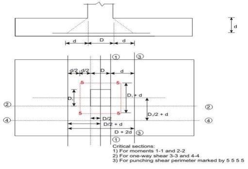
- It may be necessary to compute the bending moment at several sections of the footing depending on the type of footing, nature of loads and the distribution of pressure at the base of the footing. However, bending moment at any section shall be determined taking all forces acting over the entire area on one side of the section of the footing, which is obtained by passing a vertical plane at that section extending across the footing (cl.34.2.3.1 of IS 456).
- The critical section of maximum bending moment for the purpose of designing an isolated concrete footing which supports a column, pedestal or wall shall be:
(i) at the face of the column, pedestal or wall for footing supporting a concrete column, pedestal or reinforced concrete wall, and
(ii) halfway between the centre-line and the edge of the wall, for footing under masonry wall. This is stipulated in cl.34.2.3.2 of IS 456.
The maximum moment at the critical section shall be determined as mentioned in above. (see cl.34.2.2 of IS 456 and Figs.11.28.13a and b).
Shear force (cl. 31.6 and 34.2.4 of IS 456)
Footing slabs shall be checked in one-way or two-way shears depending on the nature of bending. If the slab bends primarily in one-way, the footing slab shall be checked in one-way vertical shear. On the other hand, when the bending is primarily two-way, the footing slab shall be checked in two-way shear or punching shear. The respective critical sections and design shear strengths are given below:
- One-way shear (cl. 34.2.4 of IS 456)
- Two-way or punching shear (cls.31.6 and 34.2.4)
Bond (cl.34.2.4.3 of IS 456)
The critical section for checking the development length in a footing slab shall be the same planes as those of bending moments in part (c) of this section. Moreover, development length shall be checked at all other sections where they change abruptly. The critical sections for checking the development length are given in cl.34.2.4.3 of IS 456, which further recommends to check the anchorage requirements if the reinforcement is curtailed, which shall be done in accordance with cl.26.2.3 of IS 456.
Tensile reinforcement (cl.34.3 of IS 456)
The distribution of the total tensile reinforcement, calculated in accordance with the moment at critical sections, as specified in part (c) of this section, shall be done as given below for one-way and two-way footing slabs separately.
(i) In one-way reinforced footing slabs like wall footings, the reinforcement shall be distributed uniformly across the full width of the footing i.e., perpendicular to the direction of wall.
(ii) In two-way reinforced square footing slabs, the reinforcement extending in each direction shall be distributed uniformly across the full width/length of the footing.
Transfer of load at the base of column (cl.34.4 of IS 456)
All forces and moments acting at the base of the column must be transferred to the pedestal, if any, and then from the base of the pedestal to the footing, (or directly from the base of the column to the footing if there is no pedestal) by compression in concrete and steel and tension in steel. The permissible bearing stresses on full area of concrete shall be taken as given below from cl.34.4 of IS 456:
br = 0.25fck, in working stress method, and
br = 0.45fck, in limit state method
Nominal reinforcement (cl. 34.5 of IS 456)
Clause 34.5.1 of IS 456 stipulates the minimum reinforcement and spacing of the bars in footing slabs as per the requirements of solid slab (cls.26.5.2.1 and 26.3.3b(2) of IS 456, respectively).
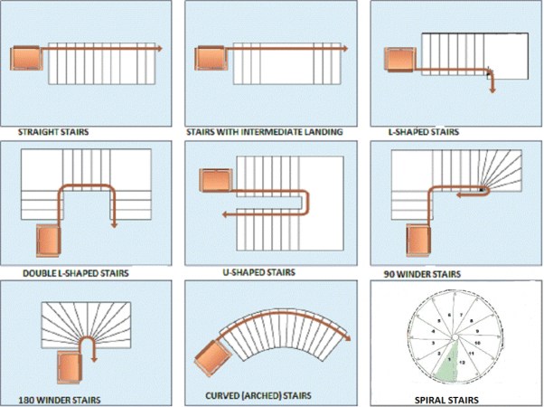
A staircase is a means of giving access to different floors or levels of a building. Stair cases used in almost all buildings. It consists of a number of steps arranged in a way that a person can move from one level to another. The arrangement of steps is as per the convenience, standards and space available. Commonly used stair cases are as follows:
(1) Straight stairs
(2) Quarter turn stairs
(3) Open well type (Half turn stair)
(4) Dog legged stairs
(5) Circular or spiral stairs
TERMINOLOGY
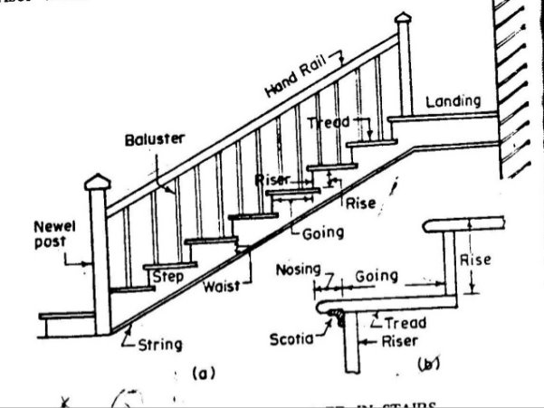
1. Flight: Flight is the length of the staircase between two landings. It is the sloping and poa (slab) of the stairs. The number of steps in a flight varies from 3 to 12.
2. Landing: Landing is the intermediate, horizontal portion provided in a staircase. It is provide for relaxing while climbing and entering or existing a staircase.
3. Rise: The vertical height of a step is called rise or riser. It varies from 150 mm to 180 mm for residential building and 120 to 150 mm for public building.
4 Tread: The horizontal distance between two risers on a step is called as tread. The width of a tread is kept as 200 mm to 250 mm for residential building and 200 to 300 mm for public building.
5. Going and Nosing: The horizontal distance between two risers is known as going and the portion projecting out from the riser surface is called as nosing. Nosing is provided when the unavailable horizontal distance for a tread is less.
6. Head Room: It is the clear height available between one fight and other above it
7. Soffit: It is the bottom surface of the waist slab.
PROPORTIONING OF STAIRCASE :
A staircase is proportional on the basis of space available and some thumb rules mentioned below
- 2x Riser + Tread = 600 to 640 mm
- Riser x Tread = 40000 to 42000 mm2
3. Width of private staircase is about 900 mm and that of public staircase is kept about 1800 mm to 2400 mm
4. Clear height between a flight and the other vertically above it (head room) should not be less.
5. The angle of flight with the horizontal should be between 25° to 40°,
6. For free flow of users the width of landing should be equal to the width of stairs than 2.10 m.
Structurally a staircase slab behaves like an ordinary slab supported on the walls or beams, It be supported in the direction of steps or in the direction of going depending upon the location of the supports. The staircase slabs are classified into two types based on the direction in which it spans
(i) Stair slab spanning horizontally
(ii) Stair slab spanning longitudinally
Stair Slab Spanning Horizontally: The stair slab supported on both sides over the walls or beams (stringer beam on one side and a beam or wall on other side) is called as stair slab spanning horizontally. The effective span of the type of stair slab is taken as the horizontal distance between centre to centre of supports. Each siep designed as a slab spanning horizontally i.e., like a rectangular beam of span (1). The stair slab spantie horizontally, along with the reinforcement.
Stair Slab Spanning Longitudinally: The stair slab supported at the bottom and top of the flight is called as stair slab spanning longitudinally. Dog legged, open well and quarter turn stairs come under this category.
Clause 33 of IS 456 gives guidelines about the design of such stairs which are to be referred.
1.Effective Span
The effective span of these stairs is taken as following:
- The centre to centre distance of the beams supporting the top nd bottom risers.
- When the landing spans parallel to the risers the effective span is taken as a distance equal to the going of the stairs plus half the width of landing on either sides or one meter whichever is smaller.
- When the landing spans parallel to the stairs, the effective span is taken as equal to the centre to centre distance of the supporting beams or walls, the going is measured horizontally in this case.
2. Loads on Staircase:
(a) Live loads: As per IS 875 live loads coming on the stair may be taken as follows:
(i) Stairs liable for overcrowding = 5 kN/m2
(f) Stairs not liable for overcrowding = 3 kN/m2.
(b) Dead loads: Dead loads are to be calculated per unit horizontal area. The dead load ofy consists of
(i) Dead weight of steps
(ii) Dead weight of waist slab
(i) Weight of one steps (for 1 m width)
W = Area of steps x 1.0 x Density of R.C.C.
3. Distribution of Loading on Stairs:
(a) In case of stairs with open wells, where spans partly crossing at right angles occur, the load on areas common to any such spans may be taken as one-half in each direction.
(b) Where flights or landing are built into walls at a distance of not less than 110 mm and designed to span in the direction of the flight, a 150 mm strip may be deduced from the loaked area and the effective breadth of the section increased by 75 mm for the purposes of design.
4. Depth of the Section:
The depth of the section shall be taken as the minimum thickness perpendicular to the soffit of the stairs.
Note: For designing the stairs, the thickness of waist slab may be assumed as 1/20 to 1/25 of span for trial section calculations.
Reference Books:
- RCC Design and drawing By Neelam Sharma
- Limit state design of reinforced concrete by P.C. Verghese, PHI
- Reinforced concrete: Limit state by A.K. Jain
- Reinforced concrete by B.C. Punamia, A.K. Jain and A.K. Jain
5. IS Code 456:2000