Module IV
Building Plumbing
- Efficient Plumbing and Drainage is an essential part of every house or building.
- Proper planning and designing of a plumbing & drainage system is crucial to meet the hygiene requirements of the occupants.
- Plumbing system is used for water supply in building .It supplies water to kitchen toilet outlets via distribution system of pipes.
- Drainage system is used to get rid of human wastes through well-arranged network of drainage pipes.
- It is important to have regular and adequate water supply and a proper system for the disposal of waste water. An efficient plumbing & drainage work keeps the atmosphere free from bad smell and ensures better sanitation.
- Around 8 per cent of the construction cost of a building is marked for plumbing and sanitary work.
- Plumbing & Drainage Cycle: Mechanism through which water is taken from a source, then supplied to the users, and finally waste water is collected and recycled to the source after proper treatment (Figure 1).
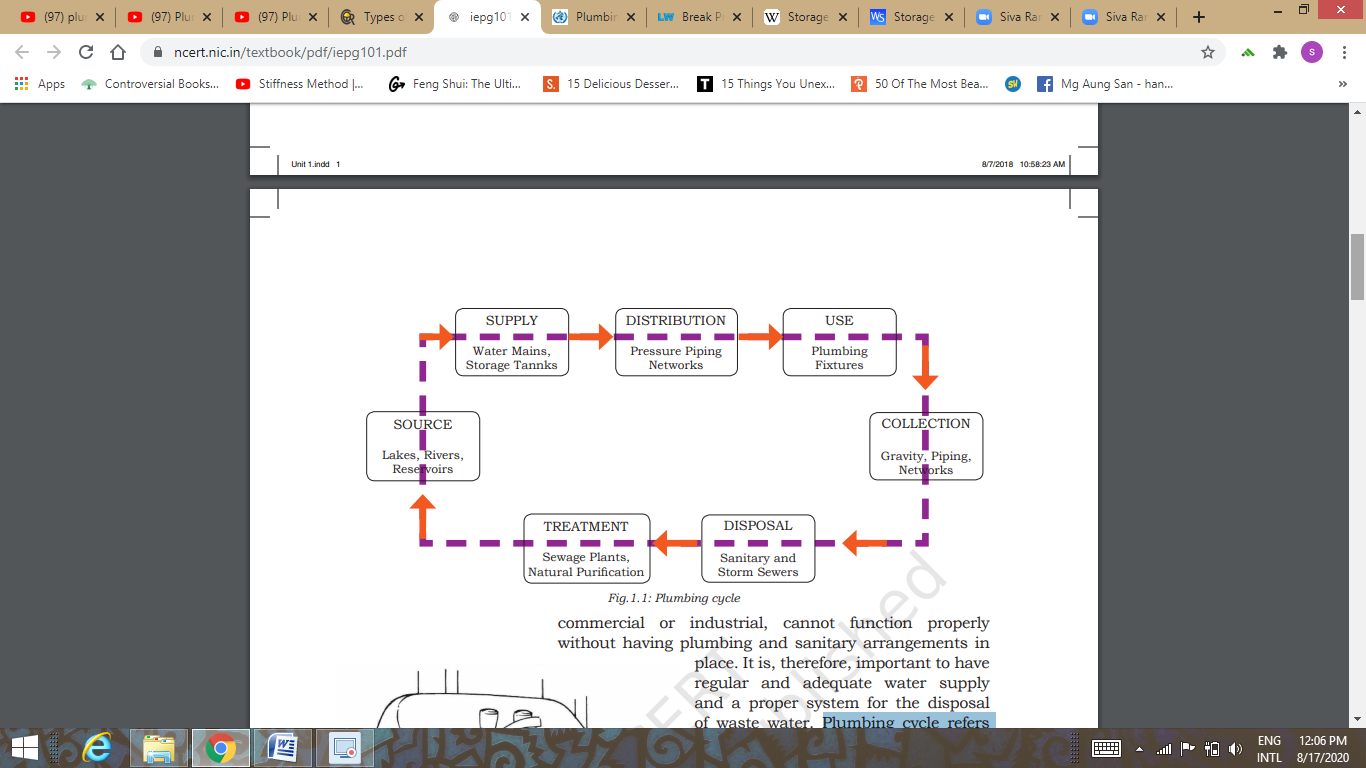
Figure 1: Plumbing & Drainage Cycle
Plumbing
It is a water distribution system of pipes, valves and fittings used to transport water from the source to the treatment plant then to the storage reservoirs before finally reaching the users.
Drainage
Drainage or Sanitary Work refers to the system of pipes & fixtures used to carry wastewater to the sewerage system.
The plumbing installation for the conveyance of water and disposal of wastewater in all buildings is governed by the rules and regulations adopted by the concerned municipal corporations or committees of different States and Union Territories.
To ensure an efficient plumbing system, it is important that standard plumbing and sanitary material, as per the Bureau of Indian Standards (BIS), are used. Quality workmanship, practical checks and supervision are ensured during plumbing and sanitary work.
Before starting the plumbing work, the plumber must keep the following points under consideration:
- Water Supply System: The source of water should be clean, hygienic and should meet potable water drinking standards
- Plumbing Fixtures and Pipes: The plumber should possess deep knowledge about different requirements and specifications
- Sanitary and Drainage System: The plumber should be well-acquainted with the local sewerage system
- Rainwater Drainage System: He should keep in mind the drainage of rainwater in areas prone to heavy rainfall and or in places where rainwater may get clogged, causing seepage in buildings
- Plumbing Drawings: The plumber should be able to read the plumbing drawings to ensure efficient plumbing in the building
PLUMBING SYSTEM
Layout of Water Distribution Network
- Dead End or Tree System
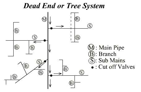
Figure 2: Dead End System
Features:
a) There is one main supply pipe that runs through the centre of the populated area and sub-mains branch off from both sides.
b) The sub-mains divide into several branch lines from which service connections are provided.
2. Grid Iron System
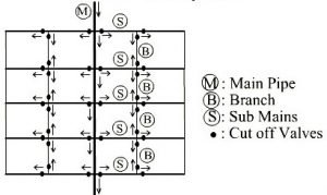
Figure 3: Grid Iron System
Features:
a) Dead ends are eliminated by inter-connecting all the lines
b) The water flows continuously in this system without stagnating
c) This system is more suitable for well-planned rectangular cities
3. Ring or Circular System
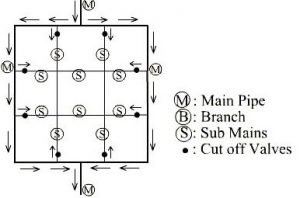
Figure 4: Ring or Circular System
Features:
a) A main pipeline is provided around the city and the branch lines are connected with each other and projected perpendicularly such that every street within the distribution area will get sufficient water supply from a number of pipes
b) This system is suitable for a town with well-planned streets and roads
c) This system is used with the grid iron system so as to enhance the capacity of the grid iron system
4. Radial System
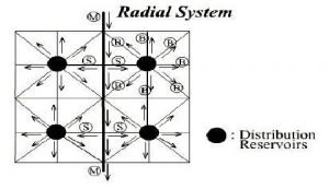
Figure 5: Radial System
Features:
a) The whole area is divided into small distribution zones and an individual reservoir is provided for each distribution zone
b) The pipelines are laid radially along the surrounding streets from this reservoir
Pipes used in Plumbing
1) Cast iron Pipes
- Corrosion resistant having long life of 100 years
- Strong & durable
- Moderate cost
- Cannot withstand pressure above 700 KN/m2
- Used as distribution mains
2) Steel Pipes
- Can withstand high internal pressure as they are strong in tension
- Cannot take heavy external load
- Susceptible to corrosion having short life span of 25-50 years
- Used in pumping mains
3) Cement Concrete Pipes
- Can resist external compressive load and do not collapse under vacuum pressure
- May undergo H2S corrosion
- Strong and have a life of 75 years
- Bulky & difficult to repair
- Tend to leak due to shrinkage cracks
4) G.I Pipes
- Can withstand acidic & alkaline action of water
- Used for carrying hot water
5) Hume Steel Pipes
- Thin steel shells coated on the inside with cement mortar
- Highly corrosion-resistant
6) Vitrified Clay Pipes
- Cannot withstand high pressure
- Extensively used for carrying sewage
7) Asbestos Pipes
- Silica & cement are converted under pressure to a stiff material called asbestos
- It can withstand a pressure of 3.5 to 14 kg/cm2
- Light and easy to transport
- Corrosion-resistant
- Hydraulically-efficient & flexible enough to permit 12ᵒ deflection
- Costly & brittle in nature
DRAINAGE SYSTEM
It is the arrangement provided in a house or building for collecting or conveying waste water through drain pipes, under the action of gravity, such that it finally reaches a public sewer or a domestic septic tank.
Terminologies related to Drainage System
Wastewater: dirty water coming out from industries, hospitals, residences etc., containing physical, chemical, and biological impurities
Sewage: wastewater coming from W.C. And containing human excreta.
Sullage: wastewater coming from bathrooms and kitchens which does not contain faecal matter
Sewer: underground conduit carrying sewage/ wastewater
Siphonage: flowing back of used, contaminated, or polluted water from a plumbing fixture or vessel into a potable water supply because of negative pressure in the pipe
Terminologies related to Drainage Devices
Cleanout: an opening that allows cleaning of the pipe
Sewerage System: system of sewers of different types and sizes in a town collecting wastewater from the town and carrying it to the wastewater treatment plant
Sanitary Sewer: sewer pipe that carries only sewage.
Storm Sewer: sewer pipe that carries storm water or other drainage excluding sewage
Building Sewer: Part of the drainage system from the building to the public disposal system
Sewer Mains: sewer pipe installed and maintained by public entity and on public property
Components of Drainage System
a) PIPES
Soil Pipe: pipe carrying sewage from W.C. (100mm dia)
Waste Pipe: pipe carrying sullage from bathrooms, kitchens, sinks, wash basins etc. (30-50mm dia for horizontal pipes and 75mm dia for vertical pipes)
Vent Pipe: vertical pipe to ensure circulation of air to and from the drainage system to protect the water seal of traps against siphonage and backflow (50mm dia)
Anti-siphonage Pipe: pipe installed to preserve the water seal in the trap through proper ventilation
Rainwater Pipe: pipe carrying rain water only (75mm dia)
b) TRAPS
Traps are U-shaped fixtures that have water seal in them which prevents sewer gas from passing from the drain pipes back into the occupied space of the building. Essentially all plumbing fixtures including sinks, bathtubs, and toilets must be equipped with either an internal or external trap.
Classification of Traps on the basis of Shape
P-Trap: exit into the wall behind the sink
Q-Trap: used in toilet under water closet
S-Trap: usually used with siphonage pipe
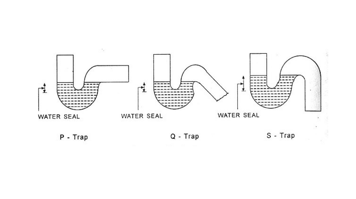
Figure 6: Classification of Traps on the basis of Shape
Classification of Traps on the basis of Use
Floor Traps (Nahani Trap): used to admit sullage from the floors of rooms, bathrooms, kitchen etc. in to the sullage pipe. This is provided with cast iron or stainless steel or galvanized gratings (Jallis) at its top so that the entry of larger matter is prevented thereby chances of blockage are reduced.
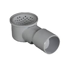
Figure 7: Nahani Trap
Gully Traps: provided at a junction of a roof drain and other drain coming from kitchen or bathroom.
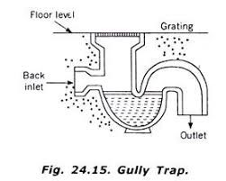
Figure 8: Gully Trap
Intercepting Traps: provided at junction of a house sewer and municipal sewer for preventing entry of foul gases of municipal sewer in to the house drainage system
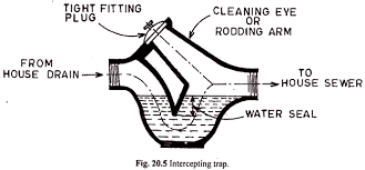
Figure 9: Intercepting Trap
c) SANITARY FITTINGS
Wash Basin: plumbing fixtures mainly used for hand-washing
Sinks: plumbing fixtures provided in kitchens for cleaning utensils
Bath tubs: plumbing fixtures provided in the bathroom for taking bath, with a circular waste hole at the bottom for drainage purpose
Water Closets: plumbing fixture designed to remove human excreta directly and dispose the same in to the soil pipe through trap
Urinals: a bowl or other receptacle, typically attached to a wall in a toilet, into which men may urinate
Basic Principles of Drainage System
- Drainage pipes should preferably be laid along the sides of the building to facilitate easy repair and better maintenance.
- The sewage or sullage should flow under the action of gravity.
- The house sewer should always be straight and the entire plumbing system should be well ventilated.
- House sewer joints should be leak-proof.
- Rainwater from roofs or open courtyards should not be allowed to flow through the house sewers.
Types of Drainage Systems
- Two Pipe System
- Best and most improved system of plumbing
- Consists of two sets of vertical pipes - one for excreta (night soil) as soil pipe and another for sullage as waste pipe
- The soil pipes as well as waste pipes are separately ventilated, by providing, separate vent pipe or anti-siphon age pipe
- This system has four vertical pipes
2. One Pipe System
- Only one vertical main pipe is provided, which collects both night soil and sullage water
- The main pipe is ventilated at the top
- In addition, a separate vent pipe is also provided
3. Single Stack System
- Consists of a single pipe for soil, waste and vent without any separate ventilation pipe
- The same pipe is extended up to 2 m above roof level with a cowl to act as vent pipe for removal of gases
4. Partially Ventilated Single Stack System
- Improved form of single stack system, where the traps of the water closets are ventilated, by a separate vent pipe, called relief vent pipe
A valve is a type of fitting that allows for regulation, control, and direction of fluids passing through a pipe. Valves are commonly used to direct flow, shut off water access, prevent backflow, and adjust water pressure within a system.
- Ball Valves
- Used for flow and pressure control and can be shut-off for corrosive fluids, slurries, normal liquid and gases
- Used in the oil and natural gas industry, manufacturing sectors, chemical storage, and even residential buildings
- Open & close quickly
- Leak-proof
- Cost-effective
2. Gate Valves/ Cut-off Valves/ Sluice Valves/ Stop Valves
- Used to cut-off the main supply whenever required and hence helpful n dividing the water mains in to suitable sections
- Placed at street corners or at pipe intersections
- Very low friction & pressure losses
- May not be very durable and are susceptible to corrosion as they are made up of iron
- Cannot be opened & closed very quickly
3. Butterfly Valve
- Designed to regulate flow, but with limited control capability
- Are very accurate and are therefore used in pharmaceutical & chemical industries
- Reliable & low-maintenance
- Do not have tight shut-offs
4. Globe Valve
- Globe valves are used to throttle or limit the flow of water
- Opening-closing time is shorter
- Lesser leakage & can be used under high-temperature conditions
- High pressure losses
5. Check Valve/ Reflux Valve
- Prevent backflow
- Reduce water hammer forces on the pump
- Required at inter-connections between a polluted water system and a potable water system
6. Pressure Relief Valve
- Reduce water hammer pressure in pipes
- Open automatically as soon as the pressure in pipes exceed a certain limit, allow some water to flow out and thus reduce the pressure
- Useful in small pipelines
7. Blow-off Valve/ Drain Valve/ Scour Valve
- Used to remove entire water from within the pipe for inspection & repair purposes
- Provided at low points for removal of silt etc
When water flows through a pipe, hydrostatic pressure is exerted on the joints & fittings of the pipe that may cause the bursting of the pipeline. In order to prevent this and break this pressure, a tank is especially built so that water can be discharged freely into the atmosphere which reduces the hydrostatic pressure to zero. Such tanks are known as Break Pressure Tanks.
A Break Pressure Tank is a non-pressurized, closed water tank that ‘breaks’ or interrupts the connection of flow from the water source.
It has an air gap to ensure zero backflow.
It is usually located downstream between the water reservoir and water supply joints.
It is the most reliable method of breaking pressure in bulk.
They are generally used in rural areas or small towns and cities where little or no maintenance is carried out.
It is made up of RCC, stone masonry, ferro-cement etc.
Advantages of Break Pressure Tanks
a) They prevent backflow between city water supply and fire pump suction
b) They create required pressure for taller buildings
c) Act as a local service reservoirs with high volume emergency storage
d) Require less maintenance
e) Even if the tank fails, the downstream pipeline will never be exposed to excessive pressures
Construction of Break Pressure Tanks
- Planning & Site Selection
Calculations are done to locate the high pressure points in the pipeline and also to determine the number of BPTs needed in the system.
Cost estimation is done to meet the budget
Availability of materials and labour is checked
2. Construction
Usually a BPT is a rectangular tank having a base of about 1000mm x 1000mm and around 1200mm high
It has a lockable lid that allows access into the tank for repair & maintenance purposes
BPTs are usually located downstream between the water reservoir and water supply joints
Components of a BPT:
- Inlet Pipe: situated at the top end of the tank; water enters at high pressure into the BPT through the inlet pipe
- Outlet Pipe: situated at the lower end of the tank; water exits at medium pressure from the BPT through the outlet pipe
- Perforated Pipe Segment
- Control Valve: to control the flow rate
- Float Device
Features
Storage Reservoirs are also known as Service Reservoirs or Distribution Reservoirs
They are used to store the treated water during low-demand periods so that it can be utilised during emergencies and high-demand periods
Functions
Help to absorb hourly variations in demand
Help to maintain constant pressure in the distribution mains
Provide water supply during emergencies
Location & Height
Should be located as close as possible to the centre of the demand
Should be at a sufficient elevation to allow gravity flow while maintaining adequate pressure
Types of Storage Reservoirs
Surface Reservoirs or Ground Reservoirs
- Rectangular or circular in shape
- Constructed on high natural ground and may be made of RCC, stones, bricks
- Side walls are designed to take up the water pressure when the reservoir is full and earth pressure when the reservoir is empty
- Bitumen compounds are used at all joints to ensure water tightness
- At the top of the roof, 60cm thick earth layer is deposited and green lawns are maintained to protect the reservoir from temperature fluctuations
- Ventilation pipes are provided to ensure circulation of air
- Stairs are provided for repair & maintenance works
Elevated Reservoirs or Overhead Tanks
- Constructed at a height sufficient to pressurize a water distribution system for the distribution of potable water
- Adopted where combined gravity and pumping system of water distribution is adopted
- May be made of steel or RCC
- Ventilation pipes are provided to ensure circulation of air
- Stairs are provided for repair & maintenance works
- Consists of a float gauge to indicate depth of water
- Has an automatic device to stop pumping when the tank is full
Capacity of Storage Reservoirs
Capacity of Storage Reservoirs is the summation of the following three factors:
- Balancing Storage: quantity of water required to be stored in the reservoir to balance the fluctuating water demand against a constant supply
- Breakdown/ Emergency Storage: storage required in times of emergencies posed by failure of pumps, electricity etc
A value of 25% of the total storage capacity of the reservoir or 1.5 to 2 times of the average hourly supply may be taken as Emergency Storage.
- Fire Storage: storage required for fire emergencies
A value of 1 to 4 lpcd (litres per capita per day) may be taken as Fire Storage.
Reference Books:
1) Santosh Kumar Garg -“Environmental Engineering (Vol. II) Sewage Waste Disposal and Air Pollution Engineering” – Khanna Publishers
2) Dr. K.N. Duggal- “Elements of Environmental Engineering” – S. Chand
Reference YouTube Video Links:
- Https://www.youtube.com/watch?v=LLIbW2xfnhk
- Https://www.youtube.com/watch?v=PzfPkBdRPWE