Module I
Introduction to Geotechnical Engineering
Basic Definitions
Geotechnical Engineering: It is the use of scientific methods and engineering principles for acquiring and interpreting materials of the Earth's crust to solve engineering problems and design engineering works. It is an applied science to predict the behaviour of the Earth and its materials and make them more suitable for structural development activities.
Geotechnical engineering comprises of Soil Mechanics & Rock Mechanics.
a) Soil Mechanics: It is a branch of civil engineering comprising of soil physics and applied mechanics that describes the behaviour of soils. It helps to analyse the deformations within natural and man-made structures that are supported on or made of soil.
b) Rock Mechanics: It is an applied science dealing with the mechanical behaviour of rock and rock masses. It is a branch of mechanics that is concerned with the response of rocks to the forces being applied in the physical environment.
Scope of Geotechnical Engineering
Design of foundations: to transmit the load of the structure to soil safely and efficiently.
Design of retaining structures: to retain soil masses at different heights on either side of the wall.
To check the stability of natural and man-made slopes in cutting and in filling.
Design and construction of underground structures such as tunnels, shafts, conduits etc that require evaluation of forces exerted by soil on these structures.
Design of a smooth and strong pavement on soil sub-grade under various conditions of loading and environmental changes.
Design of Earth Dams in which soil is used as a construction material.
Miscellaneous problems related to soil such as soil heave, soil subsidence, frost heave, shrinkage and swelling of soils.
Difference between Soil & Rock
Soil: unconsolidated agglomerate of minerals and rock particles
Rock: hard & durable material, made up of one or more minerals, that cannot be excavated without blasting
Rocks are generally cemented; soils are rarely cemented
Rocks have much lower porosity than soils
Rocks are more susceptible to weathering than soils
Rocks are usually discontinuous while soil masses can be represented as continuous
Rocks have more complex and unknowable stress history than soils
Principal stresses are vertical in rocks while they are horizontal in soils
The engineering properties of soil are cohesion, angle of internal friction, permeability, elasticity and compressibility etc while those of rocks are durability, high specific gravity, tensile strength, compressive strength
- Soils are formed by weathering of rocks due to mechanical disintegration or chemical decomposition.
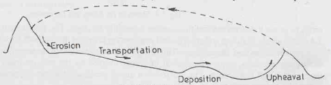
- Soils are obtained from the geologic cycle that occurs in nature consisting of erosion, transportation, deposition and upheaval of soil from one place to another, by different agents such as wind, water, air etc.
- There are two main groups of soil according to their origin:
Soil formed by physical weathering – gravel and sand
Physical processes include temperature changes, wedging action of ice, spreading of roots of plants and abrasion by different agents.
Soil formed by chemical weathering – silt and clay
Chemical processes include hydration, carbonation, oxidation and hydrolysis.
- If the products of rock weathering are still located at their place of origin, they are called residual or sedentary soils.
- Any soil that has been transported from its place of origin by wind, water, ice or any other agents and has been re-deposited at another location is known as transported soil.
- According to the agent of transportation, transported soil is further classified as:
Alluvial soils: deposited from suspension in running water
Lacustrine soils: deposited from suspension in still, fresh water of lakes
Marine soils: deposited from suspension in sea water
Aeolian soils: transported by wind
Glacial soils or Drift: transported by ice
- Some Special/ Typical Soils:
Till: directly made by melting of glaciers and may contain detectable concentrations of gems or other valuable ore minerals
Loam: mixture of sand, silt and clay
Loess: loose deposit of wind-blown silt that has been weakly cemented with calcium carbonate and montmorillonite; has high compressibility and low bearing capacity
Bentonite: chemically weathered volcanic ash
Peat: highly organic and fibrous soil and highly compressible
Muck: mixture of fine particles, organic soil and black decomposed organic matter
Peat & muck are also called cumulous soils.
Colluvial soil: accumulation of rock debris or talus at the base of a steep cliff due to action of gravity
Marl: very fine grained calcium carbonated soil of marine origin
Inducted clay: hardened clay due to heat and pressure
- Some common soils and engineering problems encountered with them:
- Alluvial deposits
Alternating layers of sand, silt and clay
Low density and liable to liquefaction in earthquake prone areas
2. Marine deposits
Very soft and may contain organic matter
Possess low shear strength and high compressibility and therefore not fit as foundation material
3. Laterites & lateritic soils
Formed from deposition of rock, removal of the bases & silica and formation of oxides of iron
These are of two types:
Primary laterite: found at high altitude near hills
Secondary laterite: found at coastal belts
Pose no difficulties as foundation material and retain their slopes well
4. Black cotton soil
Formed from basalt or trap and contain clay mineral montmorillonite, which is responsible for excessive swelling and shrinkage characteristics of soil
High plasticity and low bearing capacity
Under reamed pile foundations should be used in such type of soils
5. Desert soil
Wind-blown deposits of soil
Dune sand is non-plastic uniformly graded fine sand
Problems associated with these soils are of soil stabilisation for roads and runways, reducing settlement under static and dynamic loads and reducing its perviousness to make it suitable for storage and transportation of water
Basic Definitions
- Phase Diagram
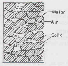
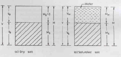
A soil mass consists of solid particles forming a porous structure. The voids in the soil mass are filled with air and water. The three constituents are blended together to form a complex material.
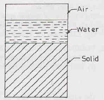
A diagrammatic representation of different phases in a soil mass is called the Phase Diagram or the Block Diagram, for the purpose of making calculations convenient. In this all the 3 phases – solid, liquid and air – of the soil mass, are segregated and placed in 3 different layers.
Usually, a 3-phase diagram is used, as shown in the figure below. As per convention, we write the volume on the left side and mass or weight on the right side of the diagram. Total volume is designated as V and it is equal to the sum of Volume of air (Va), Volume of water (Vw) and Volume of solids (Vs). Volume of voids (Vv) is the sum of volumes of air and water. Similarly, total mass is designated as M. Since the Mass of air (Ma) is very small, it is neglected. Therefore, total mass is the sum of Mass of water (Mw) and Mass of solids (Ms). Same convention is used for weights except it is designated by the letter W instead of letter M.
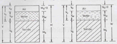
However, sometimes, a 2-phase diagram may also be considered, as shown below. The convention as discussed above is applicable here also.
i) When the soil is absolutely dry, the water phase may disappear
Ii) When the soil is fully saturated, the air phase may disappear
2. Water Content
w =  100
100
w ≥ 0 always
w = water content (%)
Ww = weight of water
Ws = weight of solids
3. Void Ratio
e = 
e > 0 always
e = void ratio
Vv = volume of voids
Vs = volume of solids
Void ratio of fine grained soils > Void ratio of coarse grained soils
4. Porosity
n =  100
100
0 < n < 100 always
n = porosity (%)
Vv = volume of voids
V = total volume of soil
5. Degree of Saturation
S =  100
100
0 ≤ S ≤ 100 always (S=0 for perfectly dry soil and S=100 for fully saturated soil)
S = degree of saturation (%)
Vw = volume of water
Vv = volume of voids
6. Air Content & Percentage Air Voids
ac =  100 = 1 - S
0 ≤ ac ≤ 100
ac = air content (%)
Va = volume of air
Vv = volume of voids
na =  100
100
na = air voids (%)
Va = volume of air
V = total volume of soil mass
7. Unit Weight
a) Bulk Unit Weight: total weight per unit volume
Ƴ = 
Ƴ = bulk unit weight
W = total weight of soil mass = Wa + Ww
V = total volume of soil mass = Va + Vw + Vs
b) Dry Unit Weight: weight of soil solids per unit volume
Ƴd = 
Ƴd = bulk unit weight
Ws = total weight of soil solids
V = total volume of soil mass = Va + Vw + Vs
c) Saturated Unit Weight: weight of fully saturated soil sample per unit volume
Ƴsat = 
Ƴsat = saturated unit weight
Wsat = total weight of saturated soil mass
V = total volume of soil mass = Va + Vw + Vs
d) Submerged Unit Weight: weight of fully saturated soil sample per unit volume
Ƴsub = 
Ƴsub = submerged unit weight of solids = Ƴsat – Ƴwater ≈ Ƴsat/2
Wsat = total weight of saturated soil mass
V = total volume of soil mass = Va + Vw + Vs
8. Specific Gravity & Apparent/ Mass Specific Gravity
Specific gravity of soil solids (G) is the ratio of the unit weight of a given volume of solids to the unit weight of an equivalent volume of water at 4ᵒC.
G = 
Furthermore, apparent specific gravity (Gm) is the ratio of total weight of a given mass of soil to the weight of an equivalent volume of water.
Gm = 
Important Relationships
- Relation between e and n
n =  and e =
2. Relation between e, w, G and S
S e = w G
3. Bulk unit weight in terms of G, w, e and Ƴw
Ƴ =  =
= 
4. Saturated unit weight in terms of G, e and Ƴw
If soil is fully saturated, S = 1
Ƴsat = 
5. Dry unit weight in terms of G, e and Ƴw
If soil is dry, S = 0
Ƴd = 
6. Submerged unit weight in terms of G, e and Ƴw
Ƴsub = Ƴsat – Ƴwater
Ƴsub =  - Ƴw
- Ƴw
Ƴsub = 
7. Relation between Ƴ, Ƴd and w
Ƴd = 
- Oven-drying Method
- Simplest and most accurate method
- Soil sample is dried in a controlled temperature (105-110ᵒC)
- For organic soils, temperature is about 60ᵒC
- Sample is dried for 24 hours.
- For sandy soils, complete drying is achieved in 4 to 6 hours.
- Water content is calculated as:
w = 
Where, W1 = weight of container
W2 = weight of container + moist sample
W3 = weight of container + dry sample
Weight of water = W2 – W1
Weight of solids = W3 – W1
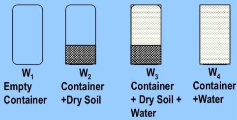
2. Pycnometer Method
- Quick method
- Capacity of pycnometer = 1000 ml = 1 litre
- More suitable for cohesionless soils.
- Used when specific gravity of soil solids is known.
- Let W1 = weight of empty pycnometer
W2 = weight of pycnometer + oven dried soil sample
W3 = weight of pycnometer + oven dried soil sample + water
W4 = weight of pycnometer + water
- Water content w =[(

 ) -1] 100
3. Calcium Carbide Method/ Rapid Moisture Meter Method
- Quick method (requires 5-7 mins) but may not give accurate results
 Reaction involved is CaC2 + 2H2O C2H2 (gas) + Ca(OH)2
- Soil sample: 4 to 6 gms
- The gauge reads water content with respect to soil weight i.e. wƳ =

- Actual water content w =
 100%
100%
4. Sand Bath Method
- Quick field method
- Used when electric oven is not available
- Soil sample is put in a container and dried by placing it in a sand bath, which is heated on kerosene stove.
- Water content is determined by the same formula as in oven drying method
5. Torsion Balance Moisture Meter Method
- Quick method used in laboratory
- Infrared radiations are used for drying samples
- The torsion wire is pre-stressed accurately to an extent equal to 100% of the scale reading. Then the sample is evenly distributed on the balance pan to counteract the pre-stressed torsion and the scale is brought back to zero. As the sample dries, the loss in weight is continuously balanced by the rotation of a drum calibrated directly to read moisture % on wet basis.
Specific gravity of solids can be directly measured by 3 methods:
- Pycnometer method (1 litre)
- Density bottle method (50 ml)
- Measuring flask method (500 ml)
Specific gravity of solids can be indirectly measured by using shrinkage limit.
The procedure for all three methods is the same. The only difference lies in the capacity of the three apparatus. Hence, the method has been explained only for pycnometer apparatus and can be applied to other two as well.
Procedure:
Let W1 = weight of empty pycnometer
W2 = weight of pycnometer + oven dried soil sample
W3 = weight of pycnometer + oven dried soil sample + water
W4 = weight of pycnometer + water
Formula:
G = 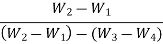
G = 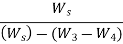
If kerosene is used instead of water,
G =  K
K
Where, K = specific gravity of kerosene
Specific gravity values are generally reported at 27ᵒC in India. However, if the sampling is done at TᵒC, then specific gravity at 27ᵒC is given by the following equation:
G27 =  GT
GT
- Core-cutter Method
- This method is used in case of non-cohesive soils but cannot be used in case of hard and gravelly soils.
- The method consists of driving a core-cutter (volume = 1000 cc) into the soil and removing it, the cutter filled with soil is weighed (W). Volume of cutter (V) is known from its dimensions and in situ unit weight (Ƴ) is measured from the formula Ƴ =

- If the water content is known, the dry unit weight can also be measured using the equation Ƴd =

2. Sand Replacement Method
- A hole is made in the ground and the excavated soil is weighed. The volume of hole is determined by replacing it with sand.
- In situ unit weight is obtained by dividing weight of excavated soil with volume of hole.
- This method is used in case of hard and gravelly soils.
3. Water Displacement Method
- Suitable for cohesive soils only, where it is possible to have a lump sample.
- A regular shaped, well-trimmed sample is weighed (W1). It is coated with paraffin wax and again weighed (W2). The sample is now placed in a metal container filled with water upto the brim. Let volume of displaced water be Vw. Then, the volume of uncoated specimen is calculated as
V = Vw - 
Where, Ƴp = unit weight of paraffin wax
And bulk unit weight of soil Ƴ = 
Reference Books:
1) A.S.R. Rao and Gopal Ranjan -“Basic and Applied Soil Mechanics” – New Age International, 2007
2) A.K. Jain and B.C. Punmia- “Soil Mechanics and Foundations” – Laxmi Publications


