Module III
Permeability of Soil
Permeability of soil is the property of soil that permits the flow of water through it. It is the ease with which water can pass through a certain soil type. It is an important engineering property and has its application in the study of a number of soil engineering problems, such as:
- Settlement of buildings
- Yield of wells
- Seepage through the earth structures
- Control of hydraulic stability of soil mass
- Design of filters in order to prevent piping in hydraulic structures
At any point in a flowing fluid, total head is the sum of datum head, pressure head and velocity head. The loss of head (Δh) per unit length of flow (L) through the soil is known as hydraulic gradient (i).
i = Δh/L
- Flow of free water through soil is governed by Darcy’s Law.
- Darcy established that flow occurring per unit time is directionally proportional to the head causing flow and the area of cross-section of soil sample but inversely proportional to the length of the sample.
Mathematically, q 
q = K 
Hence, q = K i A
Here, q = flow per unit time
K = coefficient of permeability (depends on type of soil)
i = hydraulic gradient
A = area of cross-section
Furthermore,  = K i
= K i
Now,  = v
= v
‘v’ is the velocity of flow known as discharge velocity or superficial velocity.
v = K i
- Validity of Darcy’s Law - Darcy’s Law is valid only when the following conditions are fulfilled:
Flow should be laminar and one-directional.
Slow is completely saturated.
Soil is isotropic and homogenous.
Flow is steady.
- We have already determined above that v = K i. If the hydraulic gradient is unity (i = 1), the coefficient of permeability is equal to velocity of flow (v = K).
- The coefficient of permeability is defined as the velocity of flow which would occur under unit hydraulic gradient.
- It has the dimensions of velocity and is measured in mm/sec, cm/sec, m/sec, m/day or other velocity units.
- Coefficient of Permeability can be determined from the following equation:
K = C D2 

Where, K =coefficient of permeability (m/s)
C = coefficient of proportionality
D = particle size diameter (m)
Ƴw = unit weight of water (N/m3)
µ = coefficient of viscosity (N-s/m2)
e = void ratio
- Factors affecting Coefficient of Permeability:
Particle Size: coefficient of permeability is directly proportional to the square of particle size diameter.
Structure of Soil Mass: The coefficient C takes into account the shape of flow passage, which further depends on the structure of soil mass.
Shape of Particles: For the same void ratio, angular-shaped particles have lower permeability than rounded particles.
Void Ratio: As can also be seen from the equation, greater the value of void ratio, higher is the value of coefficient of permeability.
Properties of Water: The value of unit weight of water may not vary much with temperature but the value of coefficient of permeability increases with an increase in temperature due to reduction in the coefficient of viscosity.
Degree of Saturation: Presence of air in soils causes blockage of flow passage, thereby reducing the value of coefficient of permeability.
Adsorbed Water: Adsorbed water layer is not free to move under gravity, causing an obstruction to the flow of water in pores which reduces the permeability of soil.
Impurities in Water: Presence of any impurity/ foreign matter in soil plugs the flow passage, causing reduction in the coefficient of viscosity.
The coefficient of permeability can be determined by:
a) Laboratory Methods
Constant Head Permeability Test
Falling Head Permeability Test
b) Field Methods
Pumping-in Test
Pumping-out Test
Laboratory Methods
Constant Head Permeability Test
Purpose: To find out the constant of permeability for coarse-grained, relatively permeable soil in the laboratory.
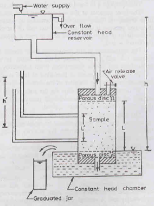
Apparatus: The constant head permeameter consists of:
a) A metallic mould of 100 mm dia, 127.3 mm height and 1000 ml capacity (As per IS: 2720 (Part XVII))
b) A detachable collar of 100 mm dia and 60 mm height, attached to the mould, required during soil compaction
c) A drainage base plate
d) A drainage cap
Diagram:
Test Procedure:
a) The soil sample is placed inside the mould, between two porous discs. The porosity of these discs should be much more than that of the soil.
b) The sample should be fully saturated before being placed in the mould. This can be done by any of the following three methods:
Filling the permeameter with water and pouring the soil into it, thereby depositing the soil under water
By allowing upward flow of water from the base to the top, after placing the soil in the mould
By applying a vacuum pressure of 700 mm of Hg for about 10-15 minutes after closing the drainage valve. De-aired water is then allowed to enter from the base to saturate the soil.
c) After saturation of soil, the constant head reservoir is connected to the drainage cap.
d) Water is allowed to flow out from the basin till a steady-state is established.
e) The chamber is filled to the brim at the start. When more water enters into the chamber, it flows over the sample and spills over in a graduated soil. This is allowed to happen for a convenient time period (t).
f) The difference in the water levels of the constant head reservoir & chamber is the head causing flow (h).
Calculation:
By Darcy’s Law, q = K i A
Therefore, q = K  A
A
Hence, we can say, coefficient of permeability, K =  (cm/sec)
Here, L = length of the specimen (cm)
A = cross-sectional area of the specimen (cm2)
h = head causing flow (cm)
q = discharge calculated by volume of water collected divided by time (cm3/sec)
Falling Head Permeability Test
Purpose: To find out the constant of permeability for clayey, relatively less permeable soil in the laboratory. It is suitable for fine sands and silts.
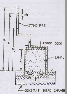
Apparatus: The falling head permeameter consists of:
a) A metallic mould of 100 mm dia, 127.3 mm height and 1000 ml capacity (As per IS: 2720 (Part XVII))
b) A vertical graduated stand pipe of known diameter
c) A drainage base plate
d) A drainage cap
Diagram:
Test Procedure:
a) The soil sample is placed inside the mould, between two porous discs. The porosity of these discs should be much more than that of the soil.
b) The sample should be fully saturated before being placed in the mould. This can be done by applying a vacuum pressure of 700 mm of Hg for about 10-15 minutes after closing the drainage valve. De-aired water is then allowed to enter from the base to saturate the soil.
c) After saturation of soil, the top and bottom outlets are closed and the stand pipe is filled with water to the required height.
d) The test starts when the water from the stand pipe is allowed to flow through the sample to the constant head chamber from where it overflows and spills out, due to which the level of water in the standpipe falls.
e) The time required for the water level to fall from a known initial head (h1) to a known final head (h2) is determined.
Calculation:
Let us consider the instant when the head = h.
If the water level in the stand pipe falls by dh over an infinitesimal small time dt, the discharge through the sample q will be given by the continuity of flow.
q = - a 
Also, by Darcy’s Law, q = K i A
Equating these two equations, we get
- a  = K
= K  A
A
On re-arranging & integrating head from h1 to h2 and time from t1 to t2, we get
- a  = K
= K 

Therefore, K =  loge
loge 
Hence, we can say K =  log10
log10 
Here, L = length of the specimen
A = cross-sectional area of the specimen
a= cross-sectional area of the stand pipe
Field Methods
Field methods to determine permeability of soil help in avoiding the difficulties involved in setting up of apparatus and following a lengthy procedure of obtaining permeability values in the laboratory.
Pumping-out Tests
A pumping-out test consists of pumping out water from a main well and observing the resulting drawdown of water table from two observation wells located at a short distance from the main well and from each other.
When a steady state of flow is achieved, the flow quantity and the water table level in the observation wells are noted down.
Assumptions:
The well penetrates the entire thickness of the aquifer.
The flow is steady and laminar.
Darcy’s law is valid.
The flow towards the well is radial and horizontal in nature.
The soil mass in the aquifer is homogeneous and isotropic.
Coefficient of permeability is uniform throughout the aquifer.
Groundwater regime remains constant.
The slope of the hydraulic gradient line is small and can therefore be taken as the tangent of the angle instead of the sine of the angle i.e., i = dz/dr.
The two types of pumping-out tests for determining permeability are:
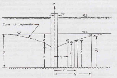
a) Unconfined Flow Pumping Test
Procedure:
In this test, pumping out of water causes a drawdown in an unconfined or open surface soil stratum which in turn generates a radial flow of water towards the pumping well.
Head h1 in observation well 1 at radius r1 from the centre of test well and head h2 in observation well 2 at radius r2 are monitored till the flow rate q becomes steady.
The rate of radial flow through any cylindrical surface around the pumping well is equal to the amount of water being pumped out.
Calculations:
Consider flow through a cylindrical surface of height z and at distance r from the centre of the test well, as shown in figure above.
From Darcy’s Law, discharge through the well q = K i A
The above equation can be written as
q = K  (2𝝿r dz)
On re-arranging and integrating the above equation, we get
 =
= 

Therefore, K =  loge
loge 
Hence, we can say K =  log10
log10 
Here, z1 = height of water level in observation well 1 at a radial distance r1
z2 = height of water level in observation well 2 at a radial distance r2
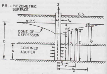
b) Confined Flow Pumping Test
Procedure:
As can also be seen in the figure, a confined acquifer of width b lies between two aquicludes such that the piezometric surface (water level) is above the top of the acquifer.
The piezometric surface is initially horizontal. As pumping starts, the piezometric line becomes depressed and a cone of depression is formed.
Calculations:
Consider flow through a cylindrical surface of height z and at distance r from the centre of the test well, as shown in figure above.
From Darcy’s Law, q = K i A
The above equation can be written as
q = K  (2𝝿rb)
On re-arranging and integrating the above equation, we get
 =
= 

Therefore, K =  loge
loge 
Hence, we can say K =  log10
log10 
Transmissibility, T = Kb
Pumping-in Tests
Pumping-in tests are conducted on the field to find out the permeability of an individual stratum of soil, through which a hole is drilled. The test gives the permeability of soil near the bore hole and is more economical than the pumping-out tests.
The two types of pumping-in tests for determining permeability are:
a) Open-end Test
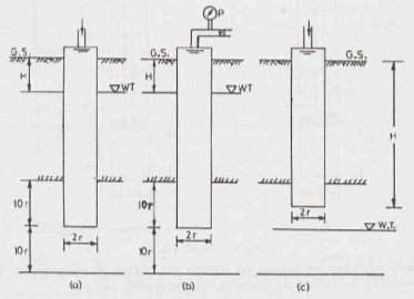
Water flows out of the test hole through its bottom end.
A pipe casing is inserted into a borehole to the desired depth and it is cleaned out.
The rate of the water that is added to the bore-hole is adjusted to maintain a constant head of water and thus a steady state is reached.
The coefficient of permeability is obtained using the equation K = 
Here, r = inside radius of the casing
H = difference of levels between the inlet to the casing and the water table
q = discharge
b) Packer Test
These are performed in an uncased portion of the pipe casing. The packer test is used for testing of rocks.
i) Single Packer Test
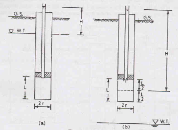
The single-packer test is used if a bore hole cannot stand without a casing pipe.
The packer is placed and water is pumped out from the hole. The water comes out of the uncased portion of the hole under the casing.
If the casing is used for full depth of the stratum, it should have holes or perforations in the portion of the stratum being tested and the lower end is plugged.
When steady conditions are attained, the rate of flow is determined. The permeability is determined using the formula:
K =  loge
loge  (if L ≥ 10r)
K =  sinh-1
  (if 10r >L ≥ r)
Here, r = inside radius of hole
L = length of the hole tested
H = difference in the water levels at the entry and the ground water table for the hole tested below the water table
Sin h-1 = arc hyperbolic sine
Ii) Double Packer Test
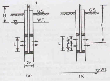
The double-packer test is used if a bore hole can stand without a casing pipe.
A pipe with two packers is fitted in to the bore hole and the bottom end of the pipe is plugged.
The test is conducted in the same way as the single-packer test and the coefficient of permeability is determined using the same equations as above.
The double-packer test is conducted first in the lowest portion near the bottom of the hole and is then repeated for upper layers.
A stratified soil is the one that consists of a number of soil layers, each having a different value of permeability.
The average permeability of the soil mass can be found out from the following methods:
a) Horizontal Flow: Flow of water is parallel to the bedding planes
Let us consider a soil deposit consisting of two layers of soil of thickness H1 and H2. Flow occurs parallel to the plane of stratification.
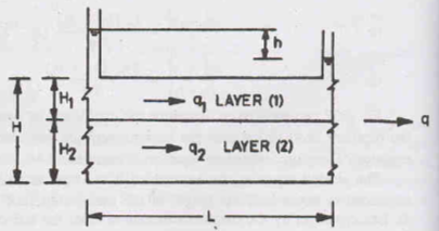
Let the discharge of the individual layers be q1 and q2.Therefore, the total discharge (q) per unit width will be q = q1 + q2. Let (Kh)1 and (Kh)2 be the permeability of the layers 1 and 2, respectively. The overall permeability Kh will be given as per Darcy’s Law:
Kh i (H1 + H2) = (Kh)1 i H1 + (Kh)2 i H2
Therefore, Kh = 
If there are n layers instead of two,
Kh = 
b) Vertical Flow: Flow of water is perpendicular to the bedding planes
Let us consider a soil deposit consisting of two layers of soil of thickness H1 and H2. Flow occurs in a direction perpendicular to the plane of stratification.
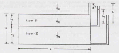
Let the discharge of the individual layers be q1 and q2. In this case, the discharge (q) per unit width over the entire deposit will be equal to the discharge per unit width of each layer i.e., q = q1 = q2. Let (Kv)1 and (Kv)2 be the permeability of the layers 1 and 2, respectively. Let us consider unit area of flow. Therefore, as per Darcy’s Law:
Kv iv 1 = (Kv)1 (iv)1 1 = (Kv)2 (iv)2 1
Equating the first and second terms of the above equation, and then the second and third terms, we get,
(iv)1 =  and (iv)2 =
Substituting these values in the first equation and solving, we get
Therefore, Kv = 
If there are n layers instead of two,
Kv = 
Seepage is defined as the flow of water under the action of gravity in a permeable medium. This flow is laminar in nature and occurs from a point of high head to a point of low head.
The path followed by the particle of water is represented by a flow line. Infinite number of lines can be drawn to show the seepage flow. However, for our ease, only a few lines are drawn.
Also, on certain points on each flow line, the value of total head is the same. These points representing equal total head are joined by lines known as equipotential lines.
The equipotential lines are always perpendicular to the flow lines and these lines together form a flow net. Thus, a flow net is defined as a pictorial representation of the path taken by water particles and the head variation along the path.
The space between two adjacent flow lines is called Flow Path or Flow Channel.
The square shaped figure formed on a flow net by two adjacent flow lines and two adjacent equipotential lines is called a Flow Field.
The Laplace Equation is used in the construction of flow net. It describes the loss of energy (hydraulic, thermal, electrical etc) in any resistive medium. For homogenous, isotropic soils, Laplace equation is given as:

Where, h = total head at any point
Stream function and potential function represent the flow of water due to change in head.
Essentially, a stream function is an equation of a streamline flow and a velocity potential function is an equation representing a change in potential.
These are functions such that their differential with respect to space gives the velocity of the fluid particle.
Stream function is represented by ψ and the velocity potential function is represented by φ.
a) Stream function: If we differentiate with respect to x, we get velocity in the y-direction (v) and on differentiating the function with respect to y we get velocity in the x-direction (u).
Mathematically,  = -v and
  = u
= u
Therefore, dψ =  dx +
dx +  dy = -v.dx + u.dy
Along a stream line, ψ is constant. Thus, dψ = 0.
Therefore, -v.dx + u.dy = 0
On re-arranging this, we get  =
=  = slope of stream lines
b) Velocity potential function: If we differentiate with respect to x, we get velocity in the x-direction (u) and on differentiating the function with respect to y we get velocity in the y-direction (v).
Mathematically,  = u and
  = v
= v
Therefore, dφ =  dx +
dx +  dy = u.dx + v.dy
Along a stream line, φ is constant. Thus, dφ = 0.
Therefore, u.dx + v.dy = 0
On re-arranging this, we get  =
=  = slope of potential lines
Orthogonality of Stream Lines and Potential Lines:
Slope of stream lines =  =
= 
Slope of potential lines =  =
= 
The product of these slopes is -1. This proves that the stream lines and potential lines are orthogonal to each other in a flow net.
Another important characteristic of the stream function as well as the velocity potential function is that they both satisfy the Laplace Equation, which is important for flow to occur.
Three fundamental characteristics need to be taken into consideration before plotting any flow net. These are, as follows:
a) The first condition that needs to be fulfilled is that every intersection between a flow line and an equipotential line must be a right angle.
b) The second important condition is that the discharge (Δq) flowing between any two flow lines and the drop in head (Δh) between two equipotential lines must always be constant.
c) For each flow field formed by two adjacent flow lines and two adjacent equipotential lines, the ratio of length to width (Δs/Δn) should be constant. For convenience purposes, this ratio is taken as 1 i.e., flow fields are in the form of approximate squares.
The graphical method of flow net construction is the most commonly used method. A lot of practice is needed to plot a good-quality flow net. However, the accuracy of the flow net does not affect the computation of hydraulic quantities such as discharge and pore-water pressure. The following points should be taken into consideration while plotting a flow-net:
1) Use of a large number of flow channels (distance between two flow lines) should be avoided as these divert the attention from essential features.
2) The appearance of the entire flow net and not just a part of it should be paid attention to.
3) Elliptical or parabolic curves with smooth transitions should be drawn.
4) Flow lines and equipotential lines should be perpendicular to each other, such that they form approximate squares.
5) The size of the squares should change gradually as we from upstream to downstream.
The following steps should be followed while plotting a flow-net:
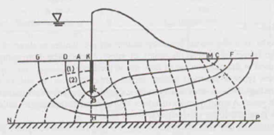
Step 1: Identify the boundary conditions of flow. As a convention, the upstream bed level, denoted by GDAK, represents 100% potential line and the downstream bed level, denoted by MCFJ, represents 0% potential line. Let us assume a flow line KLM, hugging the hydraulic structure, formed by the flow of water on the upstream of the sheet pile and at the interface of the base of the dam and the soil surface. The last flow line is indicated by the impervious stratum NP.
Step 2: Draw a trial flow line ABC near the boundary line, such that the line is perpendicular to the upstream & downstream beds. The location of this line is judged based on experience.
Step 3: Starting from the upstream end, divide the first flow channel between KL and AB into approximate squares by drawing equipotential lines such that the size of squares changes gradually.
Step 4: Extend the equipotential lines further downwards such that squares 1 and 2, as shown in the figure, are formed.
Step 5: Further extend the lines and draw another flow line GHJ.
Step 6: Repeat the entire procedure if the flow fields are inconsistent with the actual boundary conditions.
Reference Books:
1) A.S.R. Rao and Gopal Ranjan -“Basic and Applied Soil Mechanics” – New Age International, 2007
2) A.K. Jain and B.C. Punmia- “Soil Mechanics and Foundations” – Laxmi Publications