Module IV
Effective Stress Principle
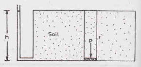
Consider a prism filled with saturated soil mass as shown in the above figure. Let the cross-sectional area of the prism be A and its height be h. The saturated unit weight of the soil is Ƴsat. The weight P of the soil in the prism is given by
P = Ƴsat h A
Total stress () on the base of the prism is equal to force per unit area. Thus,
= P/A = Ƴsat h
Pore-water pressure (u) is the upward pressure due to pore water filling the voids of the soil. Thus, u = Ƴw h
It is also known as neutral pressure or neutral stress.
Effective stress ( ) at any point is expressed as the difference between total stress and pore-water pressure.
Thus,  = - u = Ƴsat h - Ƴw h = (Ƴsat - Ƴw) h = Ƴsub h
Hence,  = Ƴsub h
In case of partially saturated soils,  = - ua + x (ua – u)
Here, ua = pore air pressure
x = fraction of a unit cross-section area of soil occupied by water = 0 for dry soil and 1 for saturated soil
All other symbols hold their usual meanings.
Importance of Effective Stress
- Effective stress controls the engineering properties of soil. Compression and shear strength of a soil depend on effective stress.
- Void ratio of the soil changes with a change in effective stress. Therefore, permeability of the soil is also affected by effective stress.
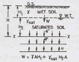
Consider a soil mass as shown in the above figure. Let the water table be at a depth of H1 below the ground level. The soil above the water has a bulk unit weight Ƴ and the soil above it has saturated unit weight Ƴsat. Let A be the cross-sectional area of the soil mass.
Case 1: At section X-X, a downward force acts due to the weight of the soil above it.
Therefore, W = ƳH1A + ƳsatH2A
Dividing both sides of the equation by A, we get
W/A = ƳH1 + ƳsatH2
Now, W/A is equal to total stress .
Hence, = ƳH1 + ƳsatH2
The pore-water pressure (u), at section X-X, which acts in the upward direction, is given as
u = ƳwH2
Therefore, at section X-X, effective stress  = - u = ƳH1 + ƳsatH2 - ƳwH2
Hence,  = ƳH1 + ƳsubH2
Case 2: If the water table rises to the ground surface, the entire soil becomes saturated and the effective stress will be given as,
 = Ƴsub (H1 + H2) = ƳsubH
Case 3: If the water table is depressed below the section X-X, the effective stress will be given as,
 = Ƴ (H1 + H2) = ƳH
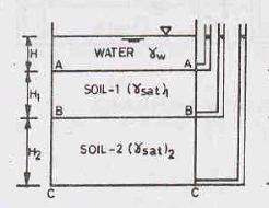
Consider a soil mass under hydrostatic conditions, as shown in the figure above. Let be the total stress at any section, u be the pore-water pressure at that section and  be the effective stress. The change in effective stress with fluctuations in the water table can be determined as follows:
Case 1: Water Table above Soil Surface A-A
Refer to figure above.
At section A-A, = ƳwH and u = ƳwH
Therefore,  = - u = 0
At section B-B, = ƳwH + Ƴsat1H1 and u = Ƴw (H + H1)
Therefore,  = - u = ƳwH + Ƴsat1H1 - Ƴw (H + H1) = (Ƴsat1 - Ƴw)H1
Hence,  = Ƴsub1H1
At section C-C, = ƳwH + Ƴsat1H1 + Ƴsat2H2 and u = Ƴw (H + H1 + H2)
Therefore,  = - u = ƳwH + Ƴsat1H1 + Ƴsat2H2 - Ƴw (H + H1 + H2)
Hence,  = Ƴsub1H1 + Ƴsub2H2
Case 2: Water Table at Soil Surface A-A
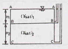
At section A-A, = u =  = 0
= 0
At section B-B, = Ƴsat1H1 and u = Ƴw H1
Therefore,  = - u = Ƴsat1H1 - ƳwH1
Hence,  = Ƴsub1H1
At section C-C, = Ƴsat1H1 + Ƴsat2H2 and u = Ƴw (H1 + H2)
Therefore,  = - u = Ƴsat1H1 + Ƴsat2H2 - Ƴw (H1 + H2)
Hence,  = Ƴsub1H1 + Ƴsub2H2
Case 3: Water Table in Soil 1 between A-A and B-B
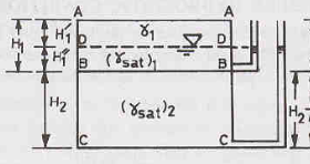
At section A-A, = u =  = 0
= 0
At section D-D, = Ƴ1H1’ and u = 0
Therefore,  = - u = Ƴ1H1’ - 0
Hence,  = Ƴ1H1’
At section B-B, = Ƴ1H1’ + Ƴsat1H1’’ and u = Ƴw H1’’
Therefore,  = - u = Ƴ1H1’ + Ƴsat1H1’’ - Ƴw H1’’
Hence,  = Ƴ1H1’ + Ƴsub1H1’’
At section C-C, = Ƴ1H1’ + Ƴsat1H1’’ + Ƴsat2H2 and u = Ƴw (H1’’+ H2)
Therefore,  = - u = Ƴ1H1’ + Ƴsat1H1’’ + Ƴsat2H2 - Ƴw (H1’’+ H2)
Hence,  = Ƴ1H1’ + Ƴsub1H1’’ + Ƴsub2H2
Case 4: Water Table in Soil 2 between B-B and C-C
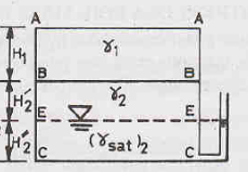
At section A-A, = u =  = 0
= 0
At section B-B, = Ƴ1H1 and u = 0
Therefore,  = - u = Ƴ1H1
At section E-E, = Ƴ1H1 + Ƴ2H2’ and u = 0
Therefore,  = - u = Ƴ1H1 + Ƴ2H2’
At section C-C, = Ƴ1H1 + Ƴ2H2’ + Ƴsat2H2’’ and u = ƳwH2’’
Therefore,  = - u = Ƴ1H1 + Ƴ2H2’ + Ƴsat2H2’’- ƳwH2’’
Hence,  = Ƴ1H1 + Ƴ2H2’ + Ƴsub2H2’’
Case 5: Water Table at Base Section C-C
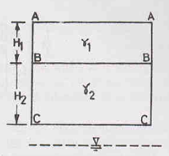
At section A-A, = u =  = 0
= 0
At section B-B, = Ƴ1H1 and u = 0
Therefore,  = - u = Ƴ1H1
At section C-C, = Ƴ1H1 + Ƴ2H2 and u = 0
Therefore,  = - u = Ƴ1H1 + Ƴ2H2
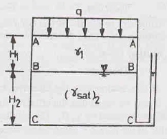
Consider a soil mass subjected to a surcharge load of intensity q per unit area and with water table is at section B-B, as shown in the figure above. Let be the total stress at any section, u be the pore-water pressure at that section and  be the effective stress. The effective stress can be determined as follows:
At section A-A, = q, u = 0
Therefore,  = - u = 0
At section B-B, = q + Ƴ1H1 and u = 0
Therefore,  = - u = q + Ƴ1H1
At section C-C, = q + Ƴ1H1 + Ƴsat2H2 and u = ƳwH2
Therefore,  = - u = q + Ƴ1H1 + Ƴsat2H2 - ƳwH2
 = q + Ƴ1H1 + Ƴsub2H2

Capillary action of water is its ability to flow through soil even in opposition to external forces like gravity. Let us consider two cases of capillary action for the soil system as shown in the above figure, with water table at B-B.
Case 1: Soil saturated up to surface level A-A (Refer to Fig a)
From the pore-pressure diagram on the right hand side of figure a, we can determine the stresses at various sections.
At section A-A, = 0, u = - ƳwH1
Therefore,  = - u = 0 - (-ƳwH1) = ƳwH1
At section D-D, = Ƴsat1H1’ and u = - ƳwH1’’ = - Ƴw (H1 – H1’)
Therefore,  = - u = Ƴsat1H1’ + Ƴw H1 - Ƴw H1’
 = Ƴsub1H1’ + ƳwH1
At section B-B, = Ƴsat1H1 and u = 0
Therefore,  = - u = Ƴsat1H1 = (Ƴsub1 + Ƴw) H1 = Ƴsub1H1 + ƳwH1
At section C-C, = Ƴsat1H1+ Ƴsat2H2 and u = ƳwH2
Therefore,  = - u = Ƴsat1H1 + Ƴsat2H2 - ƳwH2
 = Ƴsat1H1 + Ƴsub2H2 = = Ƴsub1H1 + ƳwH1 + Ƴsub2H2
Case 2: Soil saturated up to level D-D (Refer to Fig b)
At section A-A, = u =  = 0
= 0
At section D-D, = Ƴ1H1’ and u = - ƳwH1’’
Therefore,  = - u = Ƴ1H1’ + ƳwH1’’
At section B-B, = Ƴ1H1’ + Ƴsat1H1’’ and u = 0
Therefore,  = - u = Ƴ1H1’ + Ƴsat1H1’’ = Ƴ1H1’ + (Ƴsub1 + Ƴw) H1’’
At section C-C, = Ƴ1H1’ + Ƴsat1H1’’ + Ƴsat2H2 and u = ƳwH2
Therefore,  = - u = Ƴ1H1’ + Ƴsat1H1’’ + Ƴsat2H2 - ƳwH2
 = Ƴ1H1’ + Ƴsub1H1’’ + ƳwH1’’ + Ƴsub2H2
When water flows through a soil, it exerts a force on the soil particles, in the direction of flow. This force is known as drag force or seepage force and the pressure induced in the soil is termed seepage pressure.
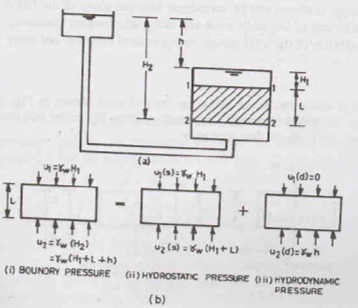
Consider the upward flow of water in a soil sample of length L and cross-sectional area A. Flow occurs under a hydraulic head h. Boundary pressures u1 and u2 act at the top and bottom of the soil sample, respectively.
The boundary water pressure is made of two components:
a) Hydrostatic pressures u1(s) and u2(s) which occur if there was no flow. These pressures would come into effect if the sample of soil is submerged under water to a depth of H1.
b) Hydrodynamic pressures u1 (d) and u2 (d) which occur if there is flow of water. These pressures would come into effect if the sample of soil is submerged under water to a depth of H1. This pressure is due to hydraulic head h.
At the top of the sample, u1 = u1(s) + u1 (d)
This can be written as ƳwH1 = ƳwH1 + 0
At the top of the sample, u2 = u2(s) + u2 (d)
This can be written as Ƴw (H1 + L + h) = Ƴw (H1 + L) + Ƴwh
Seepage force (J) which acts due to flowing water, is given by J = ƳwhA (N/m3)
Seepage force per unit volume (j) is given by j = J/ (A L) = ƳwhA/ (A L) = Ƴwh/ L
= Ƴwi
Where, i = hydraulic gradient = h/L
Seepage pressure (ps) per unit area, ps = J/A = Ƴwh
In terms of hydraulic gradient, ps = Ƴwh = (ƳwhL)/L = ƳwiL
We know that, effective stress reduces due to upward flow of water. As the head causing upward flow increases gradually, a stage comes when the effective pressure becomes zero. This condition is termed as Quick Sand Condition or Boiling Condition.
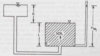
Consider a soil specimen of length L as shown in the figure above. The soil is subjected to an upward pressure. Consider section C-C at the base of the soil specimen. The downward and upward stresses developed at this section are given by:
Downward stress = Ƴsat L = (Ƴsub + Ƴw) L
Upward stress u = Ƴw Hw1 = Ƴw (L + h)
Therefore, Effective stress =  = - u = [(Ƴsub + Ƴw) L] – [Ƴw (L + h)]
 = Ƴsub L – Ƴw h
We know that hydraulic gradient i = h/L
Therefore, h = i L
Substituting the value of ‘h’ in the equation of effective stress, we get
 = (Ƴsub L) – (Ƴw i L)
If effective stress  = 0,
= 0,
Ƴsub L = Ƴw i L
Hence, i = Ƴsub/ Ƴw
The hydraulic gradient at which effective stress is zero is known as critical hydraulic gradient.
Hence, icr = Ƴsub/ Ƴw
Now, we know that Ƴsub =  Ƴw
Ƴw
Substituting this value of Ƴsub in the equation of critical hydraulic gradient, we get
icr = 
If the value of specific gravity (G) is 2.67 and that of void ratio (e) is 0.67 and we substitute these values in the above equation, we get
icr =  = 1
= 1
Thus, the effective stress becomes zero for the soil with the above values of G and e when the hydraulic gradient is unity i.e., head causing flow (h) is equal to the length of the specimen (L).
Characteristics of Quick Sand Condition:
- Shear strength of soil is zero when effective stress becomes zero. The soil is said to be in quick (alive) condition.
- A violent and visible agitation of particles occurs.
- Discharge suddenly increases due to an increase in the value of coefficient of permeability.
- If a weight is placed on the soil, it sinks down.
- Quick sand has unit weight about twice of that of water.
- If a person is caught in quick sand then the soil does not suck the victim beneath the surface but since it is highly viscous, any movement in it will require a lot of energy and effort.
Reference Books:
1) A.S.R. Rao and Gopal Ranjan -“Basic and Applied Soil Mechanics” – New Age International, 2007
2) A.K. Jain and B.C. Punmia- “Soil Mechanics and Foundations” – Laxmi Publications