Module V
Compaction of Soil
In the construction of engineering structures, loose soil must be compacted to increase their unit weights. To compact a soil means to place it in a dense state by reducing the air voids in the soil with little or no reduction in the water content.
Compaction increases the strength characteristics of the soil which increases the soil bearing capacity. Compaction also increases the stability of slopes in embankments and decreases the amount of undesirable settlement.
Purpose of Compacting Soil
- Increased Shear Strength: This means that the bearing capacity of the compacted soil increases, which allows application of larger loads to the soil.
- Reduced Permeability: This inhibits the soil’s ability to absorb water and therefore reduces its tendency to expand, shrink or liquefy.
- Reduced Compressibility: Larger loads can be applied to compacted soils since they will produce smaller settlements.
- Controlled Swelling & Shrinking of Soils
- Reduced Liquefaction Potential
Compaction is therefore defined as the process of densification of soil by removal of air, which requires mechanical energy. It is the process in which the soil particles are forced closer together with the resultant reduction in air voids.
It is assumed that the compaction process does not decrease the volume of solids or soil grains.
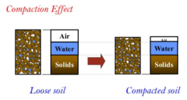
Principle of Compaction
The degree of compaction of a soil is measured in terms of the dry unit weight of the soil and its void ratio.
The more compacted a soil is:
- The smaller will be its void ratio
- The higher will be its dry unit weight
Dry unit weight of soil Ƴd =  where,
Ƴw = unit weight of water
Gs = specific gravity of soil
E = void ratio
Compaction Curve
The compaction curve is a relationship between the soil water content on X-axis and dry density of soil on Y-axis.
The relationship between dry density of soil and its water content is as follows:
Ƴd =  where,
Ƴd = dry density of soil
Ƴ = bulk density of soil
w = soil water content
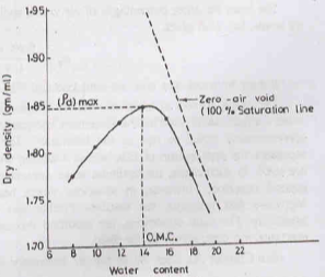
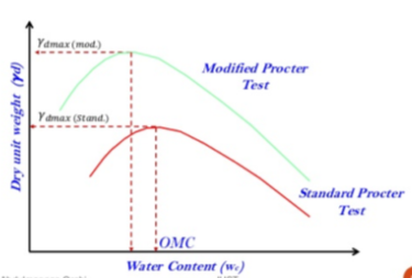
It has been observed, as can be seen from the curve also, that the dry density initially increases with an increase in water content till maximum density (d)max is obtained. With further increase in the water content, the dry density decreases.
Important Terms related to Compaction Curve
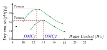
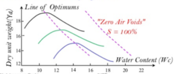
- Optimum Moisture Content or Optimum Water Content: It is the water content corresponding to maximum dry density. Each compactive effort for a given soil has its own OMC, as can also be seen the figure.
2. Zero Air Voids Curve or Saturation Line: For a known water content, theoretical maximum density is obtained when there are no air voids in the soil sample i.e., the soil is 100% saturated. This is depicted by the Zero Air Voids Curve, as shown in the figure.
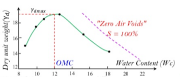
3. Line of Optimums: A line drawn through the peak points of several compaction curves at different compactive efforts for the same soil will be almost parallel to the zero air voids curve, known as the Line of Optimums. Refer to the figure below.
Factors affecting Compaction
- Water content of soil
- Amount of compaction
- Type of soil
- Amount of compactive energy
- Method of compaction
- Thickness of layer
- Saturation line
- Admixtures
- Stone content in the soil
General Methods of Compaction
| Coarse Grained Soils | Fine Grained Soils |
Laboratory |
|
|
Field | Vibration | Kneading |
|
|
Laboratory compaction tests provide the basis for determining the soil compaction needed to achieve the required engineering properties of soil at site. The aim of these tests is to determine the maximum dry unit weight that can be obtained for the given soil sample with a standard amount of compactive effort.
The proctor test is used to achieve compaction by impact energy. A hammer is dropped several times on a sample of soil kept in a mould. Standard values of the weight of the hammer, height of blows, number of blows, volume of mould etc are given in the IS Codes for different proctor tests.
According to R.R. Proctor, the compaction of a soil mass depends on the following 4 factors:
- Type of Soil
- Moisture Content
- Compactive Effort
- Dry Density of the Soil
- Standard Proctor Test
The standards for this test are given in IS: 2720 (Part VII). The test is followed for all engineering works. However, it is not sufficient for airways and highways.
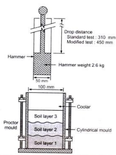
a) Take sufficient quantity of sample soil in a tray, air-dry & pulverize it using a rubber mallet.
b) Sieve the soil through a 475µm sieve & reject the coarser material.
c) Now, from the sieved soil, take about 3 kg of soil and add water to it so as to bring its water content to about 5% below the estimated OMC and mix it thoroughly.
d) Clean the mould, measure its diameter, height & then weigh it without the collar. A standard mould has internal diameter of 10.16 cm or 15.24 cm and an internal effective height of 11.7 cm.
e) Attach the collar to the mould & compact the moist soil in 3-5 equal layers each receiving blows by a hammer of 2.5 kg from a height of 300mm above the soil surface. Use 25 blows for mould of diameter 10.16 cm and 56 blows for the mould of diameter 15.24 cm.
f) The compactive energy supplied in this test is 595 KJ/m3.
g) Remove the collar and take the soil out from the mould.
h) Take about 100 grams of soil sample for water content determination by oven drying method.
i) Repeat the procedure by adding more water to the sample until the mass of the compacted soil decreases.
j) Find out the water content for each trial & calculate the corresponding dry density.
k) Plot the compaction curve between water-content as abscissa & dry density as ordinate. From this curve, find out the values of Maximum Dry Density and Optimum Moisture Content of the soil.
2. Modified Proctor Test
The Modified Proctor Test is also known as the AASHO Test as it was standardized by the American Association of State Highway Officials. The standards for this test are given in IS: 2720 (Part VIII). It is the same as the Standard Proctor Test with the following exceptions:
- Soil is compacted in 5 layers.
- Weight of hammer is 4.54 kg.
- Drop height is 450 mm.
- The compactive energy supplied in this test is 2696 KJ/m3.
The following is a comparison curve between Standard Proctor Test and Modified Proctor Test.
a) Smooth-wheel (or smooth-drum) rollers
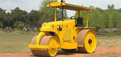
- Suitable for proof-rolling of sub-grades and finishing operations of fills with sandy and clayey soils.
- These rollers provide 100% coverage under wheels with ground contact pressure as high as 310-380 KN/m2.
- Not suitable for the application of high weights of compaction when used on thicker layers.
b) Pneumatic rubber-tired rollers

- Better than smooth-wheel rollers as they have several rows of closed spaced tires (4 to 6 in a row).
- Used for sandy and clayey soil compaction.
- Compaction action consists of combination of pressure and kneading action.
c) Sheepsfoot rollers
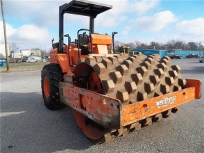
- Consist of drums with large number of projections, with area of each projection ranging from 25-85 cm2.
- Effective in compacting clayey soils.
- Contact pressure ranges from 1400-7000 KN/m2.
d) Vibratory rollers
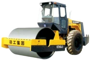
- These are extremely efficient in compacting granular soils.
- Vibrators can be attached to smooth-wheel, pneumatic rubber-tired, or sheepsfoot rollers to provide vibratory effect to the soil.
- Vibration effect is produced by rotating off-centre weights.
In majority of compaction works, it is mandatory to achieve a compacted field dry unit weight = 90-95% of the MDD obtained in the laboratory.
The ratio of dry density in the field to maximum dry density is known as relative compaction or percent compaction.
Relative compaction =  100 %
100 %
While carrying out compaction in the field, it is the duty of the geotechnical engineer to ensure that a specified amount of compaction is carried out and the desired dry density is achieved. Compaction control in the field is carried out by measuring the dry density and the water content of the soil at site.
Dry Density: It is measured by the core-cutter or the sand replacement methods (Refer to Module 1 for detailed notes on these methods).
Water Content: It is measured by the sand-bath method or the calcium carbide methods (Refer to Module 1 for detailed notes on these methods). It may also be measured using the Proctor needle or Plasticity needle.
Reference Books:
1) A.S.R. Rao and Gopal Ranjan -“Basic and Applied Soil Mechanics” – New Age International, 2007
2) A.K. Jain and B.C. Punmia- “Soil Mechanics and Foundations” – Laxmi Publications