Unit-1
Boundary Layer Analysis
- The concept of boundary layer was first introduced by L. Prandtl in 1904 and since then it applied to several fluid flow problems.
- When the real fluid flows past a stationary solid boundary, a layer of fluid which comes in contact with the boundary surface adheres to it (on account of viscosity) and conditions of no slips occurs on the surface.
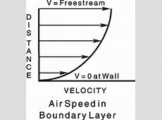
- Thus the layer of fluid which cannot slip away from the boundary surface will be undergoes retardation, this retarded layer further causes retardation for the adjacent layer of the fluid, thereby developing a small region in the immediate vicinity of the boundary surface in which the velocity of the flowing fluid increases rapidly from zero at the boundary surface and approaches the velocity of main stream. The layer adjacent to the boundary surface is known as boundary layer.
- Boundary layer is that thin layer of fluid in the immediate vicinity of bounding surface (solid body), over which velocity gradient and shear stresses are large.
- If the boundary surface and the velocity of fluid at boundary will be zero i.e. as the fluid moves pass the solid object, the molecules right next to the surfaces stick to the surface.
- The velocity is always higher away from the boundary layer due to retardation of each layer of the fluid from the boundary. Thus this will create a thin layer of fluid near surface in which velocity changes from zero at boundary surface to free stream velocity away from the surface. This is known as Boundary layer.
- It is very important in many problem of aerodynamics, because it is directly responsible for the drag experienced by body immersed in a fluid.
- In design of an aircraft, more concentration is given on controlling the behaviour of the boundary layer, to minimise the drag.
- In physics and fluid mechanics, a boundary layer is defined as the layer of fluid in the immediate vicinity of a bounding surface where the effects of viscosity are significant. In the Earth's atmosphere, the atmospheric boundary layer is the air layer near the ground will be affected by diurnal heat, moisture, or momentum transfer to or from the surface.
- According to boundary layer theory the extensive fluid medium around bodies moving in fluid can be divided into the following two regions:
- A thin layer adjoining the boundary is called the boundary layer where the viscous shear takes place.
- A region outside the boundary layer where the flow behaviour layer where the flow behaviour is quite same as that of an ideal fluid and the potential flow theory is applicable.
Assumptions of boundary layer theory:
- When a fluid flows past an object at large value of the Reynolds number, the flow region can be divided into two parts.
(i) In a thin region near the surface of the object, called the boundary layer, viscous effect cannot be neglected, and are as important as inertia.
(ii) Away from the surface of the object, viscous effect can be considered negligible, and potential flow can be assumed.
- The pressure variation calculated from the potential flow solution along the surface of the object and always neglecting viscous effects altogether, and assumed to be impressed upon the boundary layers.
- The important assumption of boundary layer approximation is that the fluid velocity at the wall is at rest relative to the surface. This will be true when the fluid pressure is very low, and therefore, the Kundsen number, KN = λ / L, of the fluid molecules is much larger than 1.
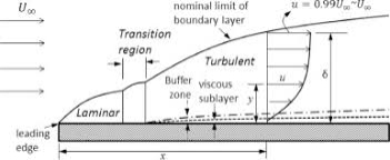
- Boundary layer is the distance from the boundary to the point where velocity of fluid is approximately equal to 99% of free stream velocity (U).
It is denoted by .
.
- When the incoming uniform flow flowing over a flat plate, the fluid particles near the plate will sticking to the plate (no-slip condition). That means that the momentum of the flat plate is diffused to the fluid. And hence the boundary layer thickness increasing as the fluid moves downstream.
- The velocity within the boundary layers increases from zero at the boundary surface to the velocity of the main stream asymptotically. Therefore the thickness of the boundary layer is arbitrarily defined as that distance from the boundary which velocity reaches 99 percent of the velocity of the free steam.
- Displacement thickness is the distance perpendicular to the boundary and by which the boundary should be displaced out-words to the compensate for reduction in the discharge in the boundary layer
- The displacement thickness, δ* or δ1 is the distance by which a surface has to be move in the direction perpendicular to its normal vector away from the reference plane in an in viscid fluid stream of velocity to give the same flow rate as occurs between the surface and the reference plane in a real fluid.
- In practical aerodynamics, the displacement thickness essentially modifies the shape of a body immersed in a fluid to allow an in viscid solution. It is commonly used in aerodynamics to overcome the difficulty inherent in the all facts that the fluid velocity in the boundary layer approaches asymptotically to the free stream value as distance from the wall could be increases at any given location.
- It is an additional wall thickness that should have to be added to compensate for the reduction in flow rate on account of boundary layer formation.
- It is not surely true that the boundary layer does not affect the potential flow at all. The potential flow streamlines just above the boundary layer will be slightly displaced away from the wall by the boundary layer.

- Suppose the potential flow of the streamline in the matching region would be at a distance h from the wall if there was no boundary layer. The displaced distance
 follows from:

- The displacement of the streamline is follows:

- Since the integrand disappears above the boundary layer, this displacement is same for all streamlines in the matching regions. Assuming that we use the boundary layer solutions for the velocity profile, then we can write

- The result of this displacement is that as far as the potential flow is concerned, the body is thicker by an amount
 :
:

- From the solution of the Blasius profile, it follows that for a flat plate in a uniform flow,

Momentum thickness
- Momentum thickness is the distance measured perpendicular to the solid boundary and by which boundary will be displace to compensate for the reduction in momentums of the flowing fluid due to boundary layer formation.
It is denoted by ( ).
).
- The momentum thickness (θ or δ2) is the distance by which a surface could have to be move perpendicular from the reference plane in an in viscid fluid stream of velocity to give the same total momentum as exists between the surface and the reference plane in a real fluid.
- It may also defined as the distance, measured perpendicular to the boundary of the solid body, by which the boundary should displaced to compensate for reduction in momentum of the flowing fluid on account of boundary layer formation. The momentum thickness is useful in kinetics.
Mass of flow per second through the elementary strip = 
Momentum/sec. Of this fluid inside the boundary layer =

Loss of momentum/sec. Of the same mass of fluid before entering boundary layer = 
Loss of momentum/sec. =  =
= 
Total of momentum/sec. = 
Let  Distance by which plate is displaced when the fluid is flowing with a constant velocity U.
Then loss of momentum/sec. Of fluid flowing through distance  with a velocity U =
By equating, we have:
 =
= 
Energy Thickness:
- It is distance perpendicular to solid boundary by which the boundary should be displaced to compensate for the reduction in kinetic energy of the flowing fluid in the formation of boundary layers.
OR
- Energy thickness (de) is defined as the thickness of an imaginary layer in free stream flow which has energy will be the deficiency of energy caused to actual mass flowing inside the boundary layer.
- Energy thickness is basically defined as the distance measured perpendicular to the boundary of the solid body and by which the boundary had displaced to compensate for the reduction in kinetic energy of the flowing fluid on account of boundary layer formation.
- Energy thickness is denoted by the symbol δ**.
Consider the fluid flow over the plate as displaced here. Now assume one section 1-1 at a distance x from the leading edge.
Mass of the fluid flowing per second through the elemental strip of thickness dy at a distance y from the plate will be given by following equation.
Mass of the fluid flowing per second = ρubdy
Where,
u = Velocity of the fluid at the elemental strip
b = width of the plate
Area of the elemental strip = bdy
Kinetic energy of this fluid with boundary layer = (1/2) x (ρubdy) x u2
Kinetic energy of this fluid without boundary layer = (1/2) x (ρubdy) x U2
Loss of kinetic energy through elemental strip = (1/2) x ρub x [U2- u2] x dy
Now we have to integrate the above equation from 0 to δ to secure the equation for loss of kinetic energy and we have following equation as mention here.
As we had discussed that energy thickness is basically the distance which is measure perpendicular to the boundary of the solid body, by which the boundary will be displaced to compensate for the reduction in kinetic energy of the flowing fluid on account of boundary layer formation.
So we can assumed that we are displacing boundary by δ** to compensate for the reduction in kinetic energy of the flowing fluid on account of boundary layer formation.
Loss of kinetic energy due to the displacement of boundary by δ** = (1/2) x (ρUb δ**) x U2
Now we will equate the both equation of loss of kinetic energy and we will have expression for the energy thickness in boundary layer.
δ ** = 
- A flat smooth plate will be placed parallel to the direction of flow then the flow in boundary layer is laminar and the main flow is turbulent near to the leading edge of plate. This layer of fluid is called as laminar boundary layer.
- The unbounded boundary layer concept had depicted for steady laminar flow along a flat plate.
- In a laminar boundary layer any exchange of mass or momentum has taken place only between adjacent layers on a microscopic scale which is not visible to our eyes. Consequently molecular viscosity
 is able predict the shear stress associated. Laminar boundary layers are found only when the Reynolds numbers are very small.
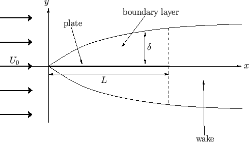
 - The lower dashed curve represents the location of the maximum velocity umax(x) and the upper dashed curve represents the location where u(x, y) essentially becomes u0, i.e. the boundary layer thickness location. Considering a flat plate of length
 , infinite width, and negligible thickness, that lies in the
  -
- plane, and whose two edges correspond to
  , and
, and .
.
 |
|
Turbulent Boundary Layer On The Flat Plate:
- If the length of the plate is more than laminar zone, the thickness of boundary layer increases in downstream direction due to the increase in
 .
. - The layer became unstable and boundary layer changes from laminar to turbulent over a short length i.e. it will be in transits zone. The layer continue to increase in downstream, such the layer is called as turbulent boundary layer.
 > 5×10^5, the layer is turbulent boundary layer.
- The laminar boundary has to be very smooth flow, while the turbulent boundary layer contains swirls or "eddies." The laminar flow creates less skin friction drag than the turbulent flow, but this is less stable. Boundary layer flow over a wing surfaces begins as a smooth laminar flow.
- A turbulent boundary layer on the other hand is mark by mixing across several layers of it. The mixing is now on a macroscopic scale. Packets of fluid may be seen moving across. Thus there is an exchange of mass, momentum and energy on a much bigger scale compared to a laminar boundary layer. A turbulent boundary layer forms only at larger Reynolds numbers. The scale of mixing cannot be handled by the molecular viscosity alone. Those calculating turbulent flow rely on what is known Turbulence Viscosity or Eddy Viscosity, which would have no exact expression. It had to be modelled. Several models have been developed for the purpose.
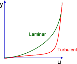
- As a consequence of intense mixing the turbulent boundary layers has been a steep gradient of velocity at the wall and therefore a large shear stress. In addition of that heat transfer rates are also high. Typical laminar and turbulent boundary layer profiles are shown in fig. Typical velocity profiles for laminar and turbulent boundary layers Growth Rate (the rate at which the boundary layer thickness
 of a laminar boundary layer is relatively very small.
For a flat plate it is given by
 |
|
Where Rex is the Reynolds Number based on the length of the plate. For a turbulent flow it is given by
 |
|
Wall shear stress is another parameter of interest in boundary layers. It is usually expressed as Skin friction defined as
 |
|
Where wall shear stress given by
 |
|
And U is the free stream speed.
Skin friction for laminar and turbulent flows are given by
 |  |
|
|
|
|
 | 
|
|
- Laminar sub layer is the region in the turbulent boundary layer zone, adjacent to the solid surface of the plate.
- The velocity variation in the region is assumed linear as it’s a very thin layer so that velocity gradient (
 ) can be considered constant.
 - The laminar sub-layer, also called the viscous sub-layer, is the region of a mainly-turbulent flow that is near a no-slip boundary and in which the flow is laminar. It is that type of boundary layer.
- The laminar sub-layer is important for river-bed ecology: below the laminar-turbulent interface, the flow is stratified, but above it, it rapidly becomes well-mixed. That threshold would be important in providing homes and feeding grounds for benthic organisms.
- Whether the roughness is due to the bed sediments or other factors are smaller or larger than this sub-layer has an important bearing in hydraulics and sediment transport. Flow is defined as hydraulically rough if the roughness elements are larger than the laminar sub-layer (thereby perturbing the flow), and as hydraulically smooth if they are smaller than the laminar sub-layer (and therefore ignorable by the main body of the flow).
- The laminar sub-layer is also called the viscous sub-layer and it is the region of a mainly-turbulent flow that is near a no-slip boundary and in which the flow is laminar. As such that it is a type of boundary layer. The existence of the laminar sub-layer has to be understood in that the flow velocity decreases towards the no-slip boundary. Because of this, the Reynolds number decreases until at some point the flow crosses the threshold from turbulent to laminar.
- When the average depth k of the surface irregularities is less than laminar sub-layer of the surface
 ) is termed as hydro-dynamically smooth boundary.
 - The eddy which forms outside of the laminar sub-layer try to penetrate in the laminar sub-layer but cannot reach to the surface irregularities due to great depth of the laminar sub layer. Such boundary is termed as smooth boundary.
- When the average depth k of the surface irregularities is greater than laminar sub-layer of surface
 is termed as hydro-dynamically rough boundary.
 - By Nikuradse’s experiments,
(i) When  < 0.25, smooth boundary.
(ii) When  > 6, rough boundary.
(iii) When 0.25 <  < 6, transition boundary
- Now, if the value of 'K' is large for a boundary then the boundary is known as Rough boundary. And if the value of 'K' is smaller or less, then the boundary is known as Smooth boundary. Those are the classification of rough and smooth boundaries based on boundary characteristics.
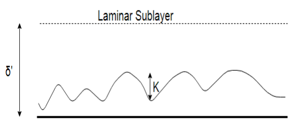
(a) Smooth Boundary
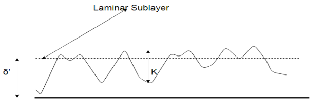
(b) Rough Boundary
Let us consider the average height of the irregularities projecting from the surface of boundary will be denoted as ‘K’.
Now, if the value of ‘K’ is large for a boundary then the boundary is termed as Rough boundary.
And if the value of ‘K’ is smaller or less, then the boundary is called as Smooth boundary.
This is the classification of rough and smooth boundaries based on boundary characteristics. But for proper classification flow and fluid characteristics are also to be considered.
- Hydro-dynamically smooth boundary:
1) For a turbulent flow analysis, the flow will be divided into two parts or portions.
2) The first portion consists of a thin layer of fluid in the immediate neighbourhood of the boundary, where the viscous shear stress is stronger whereas the shear stress due to turbulent is negligible. This is called as laminar sub-layer.
3) The second portion of flow is the one where shear stress due to turbulence is higher or larger as compared to the viscous shear and this zone has to be termed as turbulent zone.
4) The zone up to which or the height up to which the effect of viscosity predominates is denoted by δ′
5) So, we can say that if the average velocity height ‘K’ is less than ‘δ′ then the boundary is known as Smooth boundary.
6) This happens because outside the laminar sub-layer the flow will be turbulent and eddies of various sizes present in the turbulent flow try to penetrate through the laminar sub-layer, but due to the great thickness of laminar sub-layer the eddies are unable to reach the surface irregularities and so the boundary behaves as smooth boundary.
- Hydro-dynamically rough boundary:
1) If the Reynolds number of the flow increases then the thickness of laminar sub-layer decreases.
2) If this happens then the average height ‘K’ of irregularities is above the laminar sub-layer and thus the Eddies present will come in contact with irregularities of the surface and lot of energy will be lost.
3) Then such a boundary is known as Hydro-dynamically rough boundary.
Conditions from Nikuradse’s experiment:-
1) If (K′δ′) < 0.25 (smooth boundary)
2) If (K′δ′) > 6.0 (Rough boundary)
3) If 0.25 < (K′δ′) <6.0 (boundary is in transition)
- The ratio of the shear stress
 to the dynamic pressure head
 experienced at point x away from the leading edge is termed as local coefficient.
 - The ratio of total drag force to the quantity
 A, experienced by the entire plate is called as average coefficient
 - A method of correlating local and average friction coefficients for both laminar and turbulent flow of gases through a smooth tube with surface to fluid bulk temperature ratios from 0·35 to 7·35.
Boundary Layer Control:
- Boundary layer control refers to methods of controlling the behaviour of fluid flow boundary layers. It may be desirable to reduce flow separation on fast vehicles in order to reduce the size of the wake (streamlining), which may reduces drag. Boundary layer separation is generally undesirable in aircraft high lift coefficient systems and jet engine intakes.
- Methods used to control the boundary layer by sucking air through slots, making a series of small holes or porous surfaces, by blowing, or by using discrete jets. And these methods will be employed to decrease drag or to increase lift on the whole or part of the surface.
- In physics and fluid mechanics, a boundary layer is that layer of fluid in the immediate vicinity of a bounding surface where effects of viscosity of the fluid are considered in detail. In the Earth's atmosphere, the planetary boundary layer is the air layer near the ground affects by diurnal heat, moisture or momentum transfer to or from the surface. On an aircraft wing the boundary layer is the part of the flow close to the wing. The boundary layer effect occurs at the field region in which all changes occur in the flow pattern. The boundary layer distorts surrounding non-viscous flow. This is a phenomenon of viscous forces. This effect is related to the Reynolds number.
- Laminar boundary layers come in various forms and can be loosely classified according to their structure and the circumstances under which they were created. The thin shear layer which develops on an oscillating body is an example of a Stokes boundary layer, while the Blasius boundary layer refers to the well-known similarity solution for the steady boundary layer attached to a flat plate held in an oncoming unidirectional flow. When a fluid rotates, viscous forces will be balanced by the Coriolis Effect, rather than convective inertia, leading to the formation of an Ekman layer. Thermal boundary layers also exist in heat transfer. Multiple types of boundary layers can coexist near a surface simultaneously.
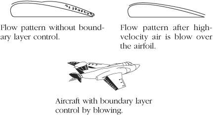
Methods Of Controlling The Separating Of Boundary Layer:
- The streaming of a body is design in such a way that the point of separation shifted as far as possible on downstream side. Due to which wake region becomes narrower and the pressure drag gets reduced.
- The artificial roughness is provided in the approach section, which changes the laminar boundary layer into the turbulent boundary layer.
- Provide the slot nearer to the leading edge so that the fluid layers remain attached to the upper surface of the body for its entire length.
- Section in which the retarded fluid is sucked out through suction slots i the boundary layer surface.
- Blowing in which additional energy will be supplied in the retarded fluid in the boundary layer by injecting high velocity fluid from the blower.
- Guide vanes and splitter vanes are provided in a confined passage to avoid separation in flow.
Boundary Layer Separation:
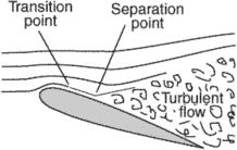
- Boundary layer separation is the detachment of a boundary layer from the surface into a broader wake. Boundary layer separation occurs when the portion of the boundary layer closest to the wall or leading edge reverses in flow direction.
- Whenever there is relative movement between a fluid and a solid surface, whether externally round a body, or internally in an enclosed passage, a boundary layer exists with viscous forces present in the layer of fluid close to the surface. Boundary layers can be either laminar or turbulent. A reasonable assessment of whether the boundary layer would be laminar or turbulent can be made by calculating the Reynolds number of the local flow conditions.
- Separation occurs in flow that is slowing down, with pressure increasing, after passing the thickest part of a streamline body or passing through a widening passage, for example-The fluid exerts a constant pressure on the surface once it had separated instead of a continually increasing pressure if still attached.
- The position at which the boundary layer leaves the surface of a solid body. It may occur with the laminar flow (laminar separation) or when the boundary layer is turbulent (turbulent separation). Separation has sometimes followed by reattachment of the flow.
- It will be observed that the flow is reversed at the vicinity of the wall under certain conditions. The phenomenon is known as separation of boundary layer.
- Separation takes place due to excessive momentum loss nearer the wall in a boundary layer trying to move downstream against increasing pressure, i.e.,
 , which is called adverse pressure gradient.
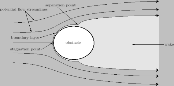
 - Reynolds number of the external flow: Suppose how obstacle is not closely aligned with the streamlines of the unperturbed flow pattern. In this case, the typically observed behaviour is illustrated in which shows the flow pattern of a high Reynolds number is not rotational fluid around a cylindrical obstacle (whose axis is normal to the direction of the unperturbed flow). It could be seen that a stagnation point, at which the flow velocity is locally zero, forms in front of the obstacle.
- Moreover, a thin boundary layer covers the front side of the obstacle. The thickness of this layer will be smaller at the stagnation point and increases towards the back side of the obstacle. However, at some point on the back side, the boundary layer separates from the obstacle's surface to form a vortex-filled wake whose transverse dimensions are similar to those of the obstacle itself. This phenomenon is termed as boundary layer separation.
|
|
- Effect of pressure gradient on boundary layer surface:
a) There will be gradual increase in velocity and drop in pressure as the floe passes from 1 to 2 i.e. pressure drop in the direction of flow,  0. The entire boundary layer moves forward, till the pressure gradient less than zero. This condition is called as favourable pressure gradient.
b) The flow retards and pressure increase as flow passes downstream from section. This condition is termed as adverse pressure gradient. Both pressure and shear force produced continuous retardation in the flow momentum and a stage comes when the momentum of the fluid is unable to overcome the surface resistance. It will be developed near the curved surface where velocity gradient  = 0. This point at which the boundary layer is on the average of separation from the surface is called as point of separation.
c) The fluid should be separated from the surface due to continuous retardation of flow. It have tendency to flow in a direction opposite to the main flow. It always occurs beyond where  0.
0.
- Location of Separation point:
Boundary layer separation will always be observed to take place at a point on the surface of an obstacle where the pressure gradient is adverse the typical transverse size of the obstacle. The separation points are the point where the air stops "sticking" to an object that is moving through the air. The point on the body where the boundary layer lifts off the surface is termed as the separation point. When the air flows separately off the surface, the pressure drag usually increases.
a) If ( ) is positive, the flow will remain attached with the surface.
b) If ( ) is zero, the flow is on the verge of separation.
c) If ( ) is negative, the flow is separated.
d) There is gradual increase in velocity and drop in pressure as the floe passes from 1 to 2 i.e. pressure drop in the direction of flow,  0. The entire boundary layer moves forward, till the pressure gradient less than zero. This condition is called as favourable pressure gradient.
e) The flow retards and pressure increase as the flow passes downstream from section. This condition is termed as adverse pressure gradient. Both pressure and shear force produced continuous retardation within the flow momentum and a stage comes when the momentum of the fluid is unable to overcome the surface resistance. It was developed near the curved surface where velocity gradient  = 0. This point at which the boundary layer is on the average of separation from the surface is known as point of separation.
f) The fluid separated from the surface due to continuous retardation of flow. It has tendency to flow in a direction opposite to the main flow. It occurs beyond where  0.
0.
