UNIT 3
Uniform flow
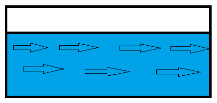
Flow in a channel is said to be uniform if the depth, slope, cross-section and velocity remain constant over a given length of the channel.Uniform flows are possible only in prismatic channels only. A uniform flow may be either steady or unsteady, depending upon whether or not the discharge reveries with time; unsteady uniform flow is rare in practice.

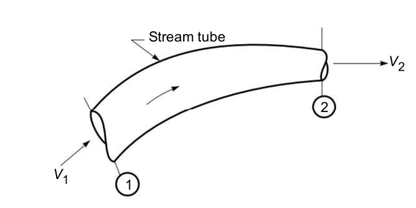
The continuity equation is based on the principle of conservation of mass. It states as follows: “If no fluid is added or removed from the pipe in any length then the mass passing across different sections shall be same. Consider two cross-sections of a pipe as shown in Fig.
Let, A1 = Area of the pipe at section 1–1,
V1 = Velocity of the fluid at section 1–1,
ρ1 =Density of fluid at section 1–1,
A2, V2, ρ2 are corresponding values at sections 2–2.
The total quantity of fluid passing through section 1–1= ρ1 A1 V1and, the total quantity of fluid passing through section 2–2 = ρ2A2V2From the law of conservation of mass (theorem of continuity)
We have: ρ1A1V1=ρ2A2V2
Equation is applicable to the compressible as well as incompressible fluids and is called Continuity Equation.
In case f incompressible fluids, ρ1 = ρ2 and the continuity equation reduces to:

A1 V1 = A2V2
3.3 Energy equation 
The general equation for conservation of energy for an incompressible fluid flow can be written as

Where qw = heat added per unit weight of fluid
e1, e2 = internal energy per unit weight of fluid at the respective states
He = external work done (i.e. shaft work added) on the fluid per unit weight of fluid from a device such as a pump
If total head 
Then above equation become

The term 
In incompressible fluid flow irreversible head is called as head loss HL and represent energy loss per unit weight of fluid due to friction and other causes.
Thus for an incompressible fluid
[Total head at section 1]+ [Head added due to machine such as pump] –[Head loss] =[Total head at section 2]
Or, 
When a pump is used He=Hp and when turbine is used He=Ht
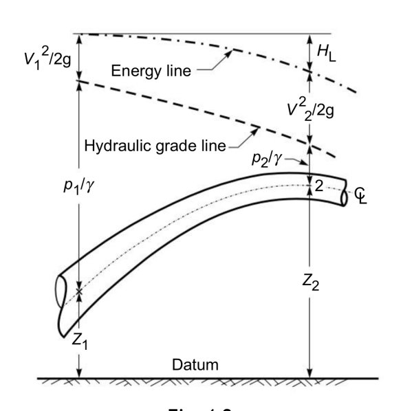
3.3.1Hydraulic Grade Line
A line joining the piezometric heads at various points in a flow is known as the hydraulic grade line (HGL). As the piezometric head h represents the variation of h measured above a datum.

The HGL represent the variation of 
3.3.2Energy line
A line joining the elevation of total energy of a flow measured above a datum is known as energy line, the energy line lies above the HGL
The total energy 
3.3.3Kinetic Energy Correction Factor
In one-dimensional method of analysis, the average velocity V is used to represent the velocity at a cross section. The actual velocity distribution in the cross section may be non-uniform. Hence, the kinetic energy calculated by using V must be multiplied by a correction factor to obtain proper kinetic energy at the cross section due to non-uniform velocity Distribution.


The momentum principle is derived from Newton’s second law and is considered under two categories as:
(i) Linear momentum equation and
(ii) Moment of momentum equation. Both the equations are applicable to a control volume and vector equation. The momentum equation for compressible fluids is similar to the one for incompressible fluids.
This is because in momentum equation the change in momentum flux is equated to force required to cause this change.
Momentum flux = Mass flux × velocity
= ρAV × V,
But the mass flux i.e. ρAV = constant ...By continuity equation.
Thus the momentum equation is completely independent of the compressibility effects and hence for compressible fluids too the momentum equation, say X-direction, may be expressed as:
ΣFx =  –
– 
3.4.1Linear momentum equation
This equation states that the vector sum of all external forces acting on a control volume in a fluid flow equals the time rate of change of linear momentum vector of the fluid mass in the control volume. The external forces are of two kinds, viz. Boundary (surface) forces and body forces.
Boundary forces consist of:
1. Pressure intensities acting normal to a boundary(Fp)
2. Shear stresses acting tangential to a boundary(Fs)
Body forces are those that depend upon the mass of the fluid in the control volume, for example weight, Fb. The linear momentum equation in a general flow can be written for any direction x as
We know that the linear momentum of the particle is
p = mv
Newton’s second law for a single particle is given by,
F = dPdt
Where F is the force of the particle. For ‘ n ‘ no. Of particles total linear momentum is,
P = p1 + p2 +…..+pn
Each of momentum is written as m1 v1 + m2v2 + ………..+mnvn. We know that velocity of the centre of mass is V = Σ
Mv = Σ mivi
So comparing these equations we get,
P = M V
Therefore we can say that the total linear momentum of a system of particles is equal to the product of the total mass of the system and the velocity of its center of mass. Differentiating the above equation we get,
 = M
= M  = MA
= MA
Dv/dt is acceleration of centre of mass, MA is the force external. So,
 = Fext
This above equation is nothing but Newton’s second law to a system of particles. If the total external force acting on the system is zero,
Fext = 0 then,  = 0
= 0
This means that P = constant. So whenever the total force acting on the system of a particle is equal to zero then the total linear momentum of the system is constant or conserved. This is nothing but the law of conservation of total linear momentum of a system of particles.
3.4.2Momentum correction factor
Momentum Correction Factor In one-dimensional flow analysis the flow characteristic in one major direction, say longitudinal axis direction, is considered and the variation in other directions neglected.
1. As depth is constant at all sections, in uniform flow the water surface is parallel to channel bottom.
2. The H.G.L is also parallel to bottom.
3. The total energy line (TEL) is also parallel to bottom.
4. Slope and bed slope (So) are equal.
5. Flow is not caused by external head but by a gravity component along the slope of the channel.
The Chezys equation can be used to mean flow velocity in conduits:
v = C (Rh S)1/2
Where,
v = mean velocity (m/s, ft/s)
C = Chezys roughness and conduit coefficient (m1/2/s)
Rh = hydraulic radius of the conduit (m, ft)
S = slope of the conduit (m/m, ft/ft)
In general the Chezy coefficient –
C - Is a function of the flow
Reynolds Number - Re
Relative roughness - ε/R
ε is the characteristic height of the roughness elements on the channel boundary.
The Manning empirical relationship is one way to estimate the roughness coefficient C:
C = (1 / n) Rh1/6
Where
n = Manning coefficient of roughness
Manning's equation can be used to calculate cross-sectional average velocity flow in open channels
v = (kn / n) Rh2/3 S1/2
Where,
v = cross-sectional mean velocity (ft/s, m/s)
kn = 1.486 for English units and kn = 1.0 for SI units
n = Manning coefficient of roughness - ranging from 0.01 (a clean and smooth channel) to 0.06 (a channel with stones and debris, 1/3 of vegetation)
Rh = hydraulic radius (ft, m)
S = slope - or gradient - of pipe (ft/ft, m/m)
Hydraulic radius can be expressed as
Rh = A / Pw
Where,
A = cross sectional area of flow (ft2, m)
Pw = wetted perimeter (ft, m)
Flow Section Channels - Geometric Relationships
The volume flow in the channel can be calculated as
q = A v = A (kn / n) Rh2/3 S1/2
Where,
q = volume flow (ft3/s, m3/s)
A = cross-sectional area of flow (ft2, m2)
- When channel applies friction to a certain flow, then the manning roughness Coefficient comes into action.
- The roughness coefficient given by manning depends on various factors like the roughness of the bed Material, variations in channel, Density and type of vegetation involved, Cross section geometry, One channel is meandered to the degree to which it is done and last but most important is Open channel flow area surface changes.
The most economical section (also called the best section or most efficient section) is one which gives the maximum discharge for a given amount of excavation.
From continuity equation it is evident that discharge is maximum when velocity is maximum, the area of cross section of channel remaining constant. From Chezy’s formula and Manning’s formula it can be seen that for a given value of slope and surface roughness the velocity of flow will be maximum if hydraulic radius A R/P is maximum.
Further the area being constant hydraulic radius is maximum if the wetted perimeter is minimum; this condition is used to determine the dimensions of economical sections of different forms of channels. The best form of channel which complies with this condition is one which has a semi-circular cross-section

3.9.1Most Economical Rectangular Channel Section
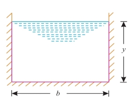
Fig. Shows the cross-section of a rectangular channel. Let b and y be the base width
And depth of flow respectively.
Area of flow, A = b × y ...(i)
Wetted perimeter, P = b + 2y ...(ii)
Substituting the value of 
From eqn. (i) in eqn. (ii), we get:

For the section to be most economical/efficient, the wetted perimeter P must be a minimum.
i.e. 
Or, 
Or, 
Or, 
Hydraulic radius, 

i.e. 
Thus the rectangular channel section will be most economical when:
(i) The depth of flow is equal to half the base width , 
(ii) Hydraulic radius is equal to half the depth of flow 
3.9.2Most Economical Trapezoidal Channel Section
Let b = Base width of the channel,
y = Depth of flow, and
θ = Angle made by the sides with horizontal.
Side slope = 1 vertical to n horizontal.

Fig. Shows the cross-section of a trapezoidal channel.


Wetted perimeter, P = AD + AB + BC = AB + 2BC (AD = BC)


=b+2

Put the value of b from equation i & ii we get,

Section of channel is most economical when wetted perimeter is minimum i.e. 
Or, 
Or, 
Or, 
Put the value of A from equation 1 in above equation


[i.e. Half of top width = One of sloping side]
Hydraulic Radius, R:

But, 


i.e. The hydrulic radius equals to half of flow depth.
Problem on economical channel section
- Determine th most economical section of rectanguar channel carrying water at rate of 0.5m^3/S, bed slope of channel is 1 in 2000 take chezys constant50
Solution-
Discgarge 
Most economical channel section:
For rectangular section
1- 
2- 
Area of flow 
Discharge 


b= 1.26m and y=0.63m
2. A rectangular channel is to be dug in the rocky portion of soil, find its most economical section if it is convey 12m^3/s of water with average velocity 3m/s. Take C= 50
Solution-


Hence, b=2.828m, y=1.414m, s=1 in 196
3.A trapezoidal channel section has side slope 3:4(H:V). Bed slope is 1in 2000 C=80 and discharge is 0.5m^3/s
Solution-
n= 3/4
S=1/2000
Q=0.5m3/s
C=80
For most economical channel section


i.e. b=y


Flow is said to be uniform when the flow depth and flow velocity remain constant and do not change with distance. The corresponding flow depth is known as the normal depth. In uniform flow condition, the weight component of water in the direction of flow is equal to the resistive force.
In uniform flow condition, the weight component of water in the direction of flow equal to resistive force
Wsin =
=
Uniform flow can be computed by two formulae:
Chezy formula:
The Chezys equation can be used to mean flow velocity in conduits:
v = C (Rh S)1/2
Where,
v = mean velocity (m/s, ft/s)
C = Chezys roughness and conduit coefficient (m1/2/s)
Rh = hydraulic radius of the conduit (m, ft)
S = slope of the conduit (m/m, ft/ft)
In general the Chezy coefficient –
C - Is a function of the flow
Reynolds Number - Re
Relative roughness - ε/R
ε is the characteristic height of the roughness elements on the channel boundary.
The Manning empirical relationship is one way to estimate the roughness coefficient C:
C = (1 / n) Rh1/6
Where
n = Manning coefficient of roughness
Mannings formula:
Manning's equation can be used to calculate cross-sectional average velocity flow in open channels
v = (kn / n) Rh2/3 S1/2
Where,
v = cross-sectional mean velocity (ft/s, m/s)
kn = 1.486 for English units and kn = 1.0 for SI units
n = Manning coefficient of roughness - ranging from 0.01 (a clean and smooth channel) to 0.06 (a channel with stones and debris, 1/3 of vegetation)
Rh = hydraulic radius (ft, m)
S = slope - or gradient - of pipe (ft/ft, m/m)
Hydraulic radius can be expressed as
Rh = A / Pw
Where,
A = cross sectional area of flow (ft2, m)
Pw = wetted perimeter (ft, m)
Flow Section Channels - Geometric Relationships
The volume flow in the channel can be calculated as
q = A v = A (kn / n) Rh2/3 S1/2
Where,
q = volume flow (ft3/s, m3/s)
A = cross-sectional area of flow (ft2, m2)
Normal depth plays a significant role in the design of open channels and in the analysis of the non-uniform flow as well. Searching for earlier literature, one can find some methods of uniform flow computation. For the most part, the well known Manning and Chezy resistance equations are extensively used. Due to their implicit form, graphical methods have been presented in the past for uniform flow computation in the common rectangular, trapezoidal, triangular and circular cross sections. For these, explicit solutions for normal depth have been proposed afterward.