UNIT 5
HYDRAULIC JUMP
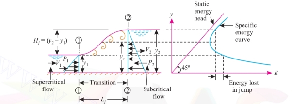
In an open channel when rapidly flowing stream abruptly changes to slowly flowing stream, a distinct rise or jump in the elevation of liquid surface takes place, this phenomenon is known a hydraulic jump (which is analogous to shock wave in compressible fluids). The hydraulic jump converts kinetic energy of stream rapidly flowing into potential energy. Due to this there is a loss of kinetic energy. At the place where hydraulic jump occurs rollers of turbulent water (eddying turbulences) form, which cause dissipation of energy. A hydraulic jump occurs in practice at the toe of spillways or below a sluice gate where the velocity is very high. The hydraulic jump is also known as a standing wave because it is, in essence, a wave which is stationary (i.e., at stand-still) at one place. Such a standing wave is shown in Fig
5.1.1Analysis of hydraulic jump:
The following assumptions are made in the analysis of hydraulic jump:
1. Loss of head due to friction at the walls and channel bed is negligible.
2. The flow is uniform and the pressure distribution is hydrostatic before and after the jump.
3. The channel is horizontal or it has a very small slope. The weight component in the direction of flow is neglected.
4. The momentum correction factor (β) is unity. Length of hydraulic jump (Lj).
1 As an energy dissipator, to dissipate the excess energy of flowing water downstream of hydraulic structures and the present seouring downstream.
2. To mix chemicals used for water purification or wastewater treatment.
3. To aerate polluted stream.
4. For desalination of sea water.
5 To raise the water level on the downstream side of a metering flume and thuamaintaing high water
6. It increases weight on an arpon and thus reduces uplift pressure under a masonry structure by raising the water depth on the apron.
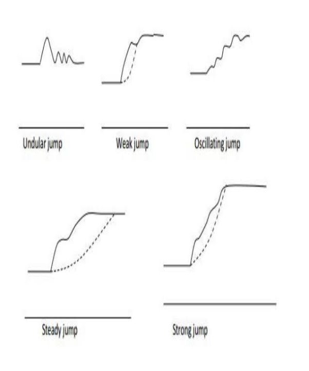
Depending on the values of Froude number F, of incoming flow, there are five distinet type of hydraulic jump.
It should be noted that the Froude number of incoming flow F, should be always greater than 1 to occur.
- Undular jump ( 1.0<F1<1.7)
Water surface is undulating with a very small ripples on the surface.
Sequent depth ratio = 0 EL/E1=0
2. Weak Jump (1.7<F1<2.5)
A series of small rollers forms on the jump surface, but the downstream water surface remains smooth.
EL/E1=5-18%
3. Oscillating jump
EL/E1= 18-45%. The entering jet of water oscillates in a random manner between bed and surface. These oscillations are very common in canals and can travel considerable distances and damaging earthen banks.
4. Steady Jump 4.5 < F, 5 9.0,
EL/E1= 45 70%
The jump is well established, the roller and jump action is fully developed to cause appreciable energy loss
5. Strong or Choppy Jump
EL/E1> 70%,
F1> 9.0,
During this jump water surface is very rough and Choppy, which continues downstream for a long distance,
Sequent depth ratio is quite large.
Energy dissipation is very efficient.
Length of hydraulic jump represents that short distance over which the jump occurs (Refer Fig. 16.26). For rectangular channels with horizontal floor, length of a jump has been found to vary between 5 to 7 times the height of the jump i.e.,
Lj = 5 to 7 Hj


In case of hydrostatic pressure distribution, pressure force at any section.

Where, y= vertical depth of centroid of wetted area from the liquid surface


Net force acting on mass of water between 1-1 and 2-2


[P2>P1 as y2>y1]
Now change in linear momentum equation = pq (V1-V2)
But according to impulse momentum equation:
Net force acting on mass of fluid = Rate of change of momentum in the same direction

Put 


Devide both side by y2-y100


Multiply both side by y2


Or 
Neglecting the second root, we have


Expand y2 in terms of froud number (Fr):


Loss of energy due to hydraulic jump is equal to the difference of specific energies at the upstream (1-1) and downstream (2-2) sections.


 -
-
= -
-

 -1]
-1]

=

When water flows from crest and if the difference in upstream and downstream water level is more. This causes small very high velocity.
This high velocity has a very high kinetic energy which can cause dangerous score of the channel bed causing failure of spillway.
Therefore it is essential to reduce this kinetic energy of flow and this is done by energy dissipaters.
Thus energy dissipaters is a structure constructed near toe of spillway to reduce the high energy of flow.
5.7.1The different types of energy dissipaters are:
- Hydraulic jump type. 2. Bucket type.
Due to heavy turbulence it is essential to produce hard floor.
For hydraulic jump sloping glacis are preferred to a horizontal bed and jump is made to occur on the glacis only.
In bucket type energy dissipater flow of water is directed into air and thus fall occurred away from toe of dam.
These are suitable under any conditions of the water provided good hard rock is available. These are more economical than hydranlic jump type.
The energy is destroyed by a creation of jet and impact of water on the bed of river and scouring takes place which is small and away from toe.
Types of buckets
1. Solid roller bucket
2. Slotted roller bucket
3. Ski-jump bucket
- 1. Solid roller bucket
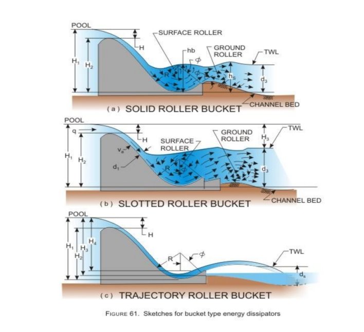
This type of bucket consist of a concave circular apron of large radius and a deflector lip. Fig. Shows solid roller bucket.
Water flow when water flows over the solid roller bucket, then complete shoet of water leaving the bucket is jumped upward by the bucket lip and two elliptical rollers are developed as shown.
Two elliptical rollers moves in clockwise direction and anticlockwise direction.
2. Slotted roller bucket A slotted roller bucket consists of concave circular apron having large radius; like solid circular bucket, only difference is that it has slotted deflector lip as shown in. In such type of bucket also two rollers are developed as developed in solid roller bucket. But in this type water leaves lip of the bucket at a flatter angle and only a part of it get jumped upwards. In this case, less violent ground roller occurs which makes the smoother flow on d/s side. The slotted roller buckets are suitable only for a limited range of tail water depth because excessive large jet of water leaving lip get depressed and drive to the river bed which will scour the bed. Fig. 5.8.5 shows hydraulic action in slotted roller bucket.
- 3. Skl-jump bucket when tail water depth is less, then in such case a ski-jump bucket can be used. In such bucket the lip of the bucket is shaped in such way that the complete sheet of water flowing over the bucket is jumped or deflected as a free jet. This-free i.e., further falls back into the river at a safe distance away from the spillway.
A surge wave (often simply called a surge), we have noted, is a moving wave front which brings about an abrupt change in the depth of flow in a channel. As a further example, we can consider a wave, as a surge, that is created due to a landslide fall into a river and consequent partial blockage of the main flow. The waves that are created due to sudden opening (pointed out earlier) and sudden closing of sluice gates in irrigation and power canals (Figure 11.2) are also surges. Depending upon the direction of progress of the wave front. Hydraulic surges are created when the velocity of a fluid suddenly changes and becomes unsteady or transient. Fluctuations in the fluid's velocity are generated by restrictions like a pump starting/stopping, a valve opening/closing, or a reduction in line size. Hydraulic surges can be generated within a matter of seconds anywhere that the fluid velocity changes and can travel through a pipeline at very high speed, damaging equipment or causing piping failures from over pressurizing. Surge relief systems absorb and limit high-pressure surges, preventing the pressure surge from traveling through the hydraulic system. Methods for controlling hydraulic surges include utilizing a gas-loaded surge relief valve, spring-loaded pressure safety valves, pilot-operated valves, surge suppressors, and rupture disks.
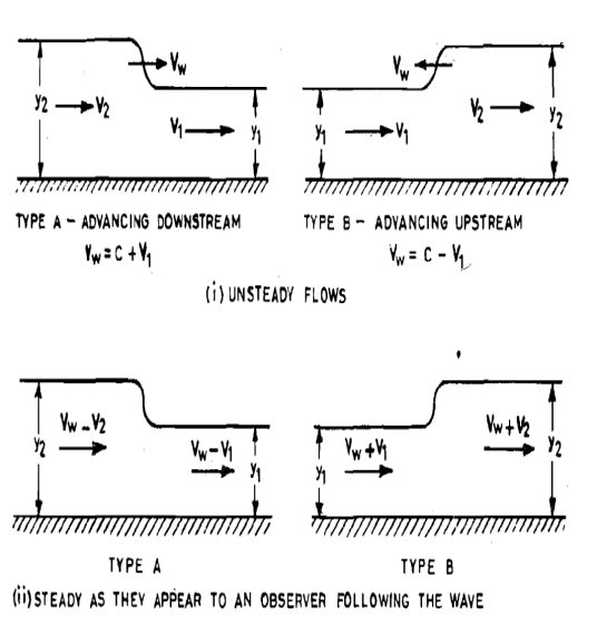
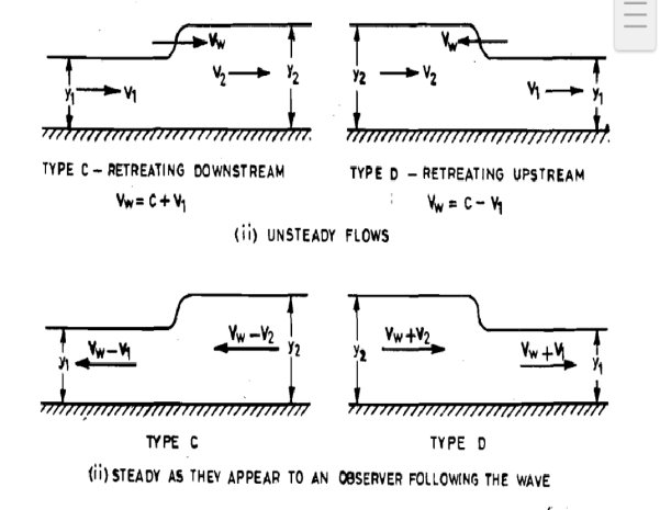
A surge or surge wave is a moving wave front which brings about an abrupt change in depth of flow. A surge is also often referred to as moving hydraulic jump and is caused by sudden increase or decrease in flow, such as that caused by sudden opening or closing of a gate fixed in the channel. Surges are usually classified as positive surges and negative surges. A positive surge is one which results in an increase in the depth of flow and a negative surge causes a decrease in the depth of flow, and shows two types of positive surges shows two types of negative surges. Type A is a positive surge having an advancing wave front moving downstream. Type B is also a positive surge having an advancing wave front moving upstream. Type C is a negative surge having a retreating wave front moving downstream, is also a negative surge having a retreating wave front moving upstream. The positive surge of type A may occur when a gate provided at the head of a channel is suddenly opened. The positive surge of the type B may occur when a gate provided at the tail end of a channel is suddenly closed. The negative surge of type C may occur when a gate provided at the head of a channel is suddenly closed. The negative surge of type Dmay occur when a gate provided at the tail end of a channel is suddenly opened.
5.8.1Application of surge
Surge control products have been used in many industries to protect the maximum working pressure of hydraulic system for decades. Typical applications for surge relief equipment is in pipelines at pump stations, receiving manifolds at storage facilities, back pressure control, marine loading/off loading, site specific applications where pressure surges are generated by the automation system, or any location deemed critical by an engineering firm performing a surge analysis.
Types
- Positive Surges :
These are the ones which elevate the water surface from an initial low stage to a final high stage and advance the wave front either downstream or upstream with a stable wave front
Positive surges are generally caused due to sudden increase in the flow and negative surges re the result of sudden decrease or stoppage of flow. Surges can be classified as described elow. It is a positive surge advancing downstream. Waves created in natural rivers due to dam breaks and those caused in irrigation and power canals by sudden opening of head gates
It is a positive surge advancing upstream. This is also known as a reje surge. Inland tidal movements in estuaries and those caused in irrigate power canals by sudden closing of tail gates fall under this type of surge
Positive Surge due to sudden increase of flow Consider a positive surge of type A created in a rectangular channel by suddenly opening a gate as shown in. Let V be the absolute velocity of the surge moving towards right and let V, and V, be the velocities and y, and y, be the corresponding depths at sections I and 2 respectively. In order to make it a case of steady flow, apply velocity V in opposite directions to the velocities V, and V, and the surge. Thus the velocities at sections 1 and 2 becomes respectively.
2. Negative Surges:
These are the surges which depress the water surface from an initial high stage to a final low stage and retreat either downstream or upstream with an unstable wave front. It is a negative surge retreating downstream. Waves caused by the clos head gates in canals or gates at the tail races of hydro-power plants are grouped under this type;
It is a negative surge retreating upstream. This is also known as a dem surge. Waves caused on the upstream sides of tail gates in irrigation ar power canals due to the sudden opening of gates in order to meet the increased demands on the downstream sides fall under this type.
Negative Surges Negative surges are not stable in formi because as indicated below the upper portions of the wave travel faster than the lower portions. If y, is the depth below the top a, b, of the wave and y, is the depth below the bottom or trough, of the wave, then since celerity its value at the top a, b, of the wave is and at the bottom of the wave is greater than Thus if the initial profile of the surge is assumed to have a steep front, it will soon flatten out as the surge moves through the channel. If the height of the surge is moderate or small compared with the depth of flow, the equations derived for a positive surge can be applied to determine approximately the propagation of the negative surge. However, if the height of the surge is relatively large, a more elaborate analysis as indicated below may be adopted. A negative surge of type D of relatively large height retreating in upstream direction in a rectangular channel. The surge is caused by the sudden lifting of a gate. In this case the velocity of the surge actually varies from point to point. Let V be the velocity of the surge at a point on its surface where the depth is y and the velocity of flow through the section is V. During a time interval dt, let the change in y be dy. The value of dy is positive for an increase of y and negative for a decrease of y. Assuming that the rate of change in y varies uniformly from O to dy in time di, the average change dy is The mass of water that moves per unit width of the channel is equal to is in a direction opposite to Va. If the change in Jev+ V), as V is in a direction opposite to Vy. If the change in velocity is dV, then the rate of change of momentum of the vertical element dy)
1. A sluice gate discharges water into horizontal rectangular channel with a velocity of 10 m/s and depth of flow of 1 m, Determine the depth of flow of water after the jump and consequent loss in total head
Solution.
Velocity of flow before hydraulic jump, V1= 10 m/s.
Depth of flow before hydraulic jump, y1= 1 m
Depth of flow after the jump, y2
Discharge per unit width,
q= V1× y1
= 10 × 1 = 10 m3/s per m
The depth of flow after the jump is given by:


Y2= 4.043m


EL=1.742m...
2. A 3.6m wide rectangular channel convey 9m3/s water with velocity of 6m/s
i- If there a condition for hydraulic jump to occur? If so, calculate length, height and strength of jump.
Ii) What is loss of energy per kg of water?
Solution-
b =3.6m
Q= 9m3/s
V1= 6m/s
i- Is there a condition for hydraulic jump to occur?
Depth of water before jump, 


= 2.5m3/s per meter


Yc=0.86m
 jump would occure


Ii- 
V1=6m/s


 m/s
m/s


3. In a rectangular channel of width 0.5m, a hydraulic jump occurs at a point where depth of water flow is 0.15m and froude number is2.5, determine
i-the specific energy
Iii- Critical and subsequent depth
Iv- Loss of head iv- Energy dissipated
Solution-
b= 0.5m
y1=0.15m
Fr=2.5


