UNIT 5
GROUND WATER AND WELL HYDROLOGY
DISTRIBUTION OF SUB-SURFACE WATER:
- Sub-surface water (i.e., all forms of groundwater) can broadly classify as:
(1) The portion in unsaturated zone, (Aeration zone)
(2) The portion in saturated zone (ground water zone)
- The unsaturated zone comprises of three subsurface zones -soil water zone, Intermediate zone, capillary zone.
Soil Water Zone
- Soil water zone encompasses the zone from the ground surface down to the roots from where water is drawn by vegetation; it is also called soil-moisture belt and its thickness depends upon the type of vegetation that is being fed. This zone remains unsaturated except during periods of heavy infiltration. In this region, soil water is classified in three main classes.
They are:
Hygroscopic water:
- Water is held tightly to the surface of soil particles by adsorption forces in the form of thinnest film with soil water tension about 31 atmosphere and above.
Capillary water:
- Water held by surface tension in the capillary space in the form of a thickest film with tension about 1/3 atmosphere.
Gravitational water:
- Water that moves freely in response to gravity through micro pores and drains out soil.
Intermediate Zone:
Intermediate zone extends from the bottom of the soil water zone down to the top of the capillary fringe
- It greatly varies in thickness from no thickness to several hundred meters.
- All the infiltration water must pass through this region
Capillary Zone:
- Capillary zone is the zone of soil commencing from the water label to the top of the capillary rise zones.
- It is the zone which is fully saturated at the equilibrium stage; however, the pressure in this zone is less than atmospheric because of the capillary potential within the capillary fringe. For this reason this zone is taken as a part of the unsaturated zone.
- Capillary rise depend on the size of pores (which is a function of soil particle size) and further on rise fall in water table.
- The thickness of this zone is a function of the texture of soil; therefore, it varies from region to region well as from place to place within a given area.
Saturated Zone:
- In the saturated zone, ground water fill the pore space completely and water is stored as in a reservoir have a hydrostatic pressure variation throughout its depths with atmospheric pressure assumed to exist at the water table.
- All earth materials, from soils to rocks have pore spaces. Although these pores are completely saturated water below the water table, from the groundwater utilization point of view, only such material through which water moves easily and hence can be Extracted with ease are significant On this basis, the saturated formation are classified into four categories.
(1) Aquifer,
(2) Aquitard,
(3) Aquiclude, and
(4) Aquifuge.
Aquifer:
- An aquifer is a saturated formation of earth material which not only stores water but yields it in sufficient quantity relatively easily due to its high permeability. Deposits of sand and gravel form good aquifers.
Aquitard:
- It is a formation through which only seepage is possible and thus the yield is insignificant compared to aquifers. A sandy clay unit is an example of aquitard.
Aquiclude:
- Formations like clay which is highly porous but not permeable due to very small size of pores
Aquifuge:
- It is a geological formation which is neither porous nor permeable. Massive compact rock without any fractures
TYPES OF AQUIFERS:
Unconfined Aquifers
- Unconfined aquifers are one which signifies the absence of any geological layer confining the zone of saturation (above the water table). The unconfined aquifer in direct contact with atmosphere through the zone of aeration. The hydraulic pressure head at any point within the unconfined aquifer is equal to depth of the point from the water table,
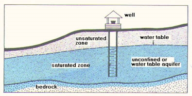
- In unconfined aquifer the water table down if water is withdrawn from the aquifer storage and the water table moves up if water is added into the aquifer storage
- The water level in a large diameter dug wells tapping unconfined aquifer represents water table. This aquifer is also known as water table aquifer or prelatic aquifer.
- A special case of unconfined aquifer is known as perched aquifer. A perched aquifer is formed when the infiltrated rain water is intercept within the zone of Aeration by an impermeable layer and a local zone of saturation is formed. The upper surface of such local zone of saturation is known as perched water table
Confined Aquifers:
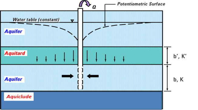
- A confined aquifer (also called artisan aquifer) is the one which is overland by an impermeable layer or an Aquiclude. Unlike the unconfined aquifer, the water in the confined aquifer is not in direct contact with the atmosphere.
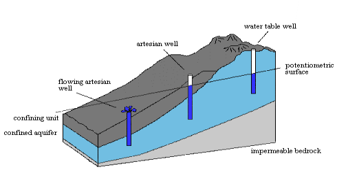
- The ground water within a confined aquifer occurs under Pressure (known as confined pressure or artisan pressure) greater than atmospheric pressure. When such confined aquifer is pierced by a well, the water rises in the well due to release of pressure within confined aquifer. The level up to which water will rise in the well is known as potentiometric level. This potentiometric level indicates the magnitude of pressure within the confined aquifer. If the potentiometric level is above the ground surface flowing well results
- The area from which the infiltrated water enters the confined aquifer is known as Recharge area.
AQUIFER PROPERTIES:
An aquifer performs two functions
1. Storage of water, and
2. Transmission of stored water.
- The porosity and the hydraulic conductivity (permeability) explain the storage and transport of water.
Porosity
- The amount of pore space per unit volume of the aquifer material is called porosity. It is expressed as
n=Vv /V0
Where n =porosity, Vv =volume of voids and V0= volume of the porous medium.
Specific Yield:
- While porosity gives a measure of the water-storage capability of a formation, not all the water held in the pores is available for extraction by pumping or draining by gravity. The pores hold back some water by molecular attraction and surface tension.
- The actual volume of water that can be extracted by the force of gravity from a unit volume of aquifer material is known as the specific yield, Sy The fraction of water held back in the aquifer is knownas specific retention also called field capacity Sr Thus porosity
n = Sy + Sr
Porosity and specific yield of selected formations
FORMATION | POROSITY (%) | SPECIFIC YEILD (%) |
Clay | 45 to 55 | 1 to 10 |
Sand | 35 to 40 | 10 to 30 |
Gravel | 30 to 40 | 15 to 30 |
Note that although clay is more porous than sand, the specific yield of clay is very small compared to that of sand
Storage Coefficient (or Storability) (S):
- In case of confined aquifer, volume of water given by unit plan area. Of aquifer when piezometric surface falls by unity is called storage coefficient
- For unconfined aquifer storage coefficient is assumed to be equal to specified yield.
Storage coefficient of an artesian aquifer is given by the relation.
S =Ywnb (1/Kw + 1/ nEs )
Where, S= storage coefficient
Yw= specific weight of water
n= porosity of soil
b= thickness of the confined aduifer
Kw= bulk modulus of elasticity of water
Es= modulus of compressible (elasticity) of the soil grains of the aquifer.
- Since water is practically incompressible expansibility of water as it comes out of the pores has a very little contribution to the value of the storage coefficient.
- Since water is under pressure in confined aquifer, draining of water leads to decrease in pore pressure and hence increase in effective stress. This increase in effective stress leads to compression of soil Skelton. Thus Specific storage is solely due to compression of aquifer and expansion of water.
- Storage coefficient per unit depth of confined aquifer is called specific storage (Sa)
S =Sa .b
b= depth of confined aquifer.
- Thus sp. Storage is defined as volume of water released from storage from a unit volume of aquifer due to unit decrease in piezometric head,
Note: When we talk of well we define a new quantity called specific capacity. Sp. Capacity is the discharge from well per unit drawdown of well
Darey's Law:
V= Ki. .............( Darcy's law)
Where V= Apparent velocity of seepage = Q/A in which Q= discharge and A = cross-sectional area of the porous medium. V is sometimes also known as discharge velocity. i =-dh/ds = hydraulic gradient, in which h piezometric head and s = distance measured in the general flow direction the negative sign phasizes that the piezometric head drops in the direction of flow. K=a coefficient, called coefficient of permeable (hydraulic conductivity) having the units of velocity...
The discharge Q can be expressed as
Q=KiA
Darey's law is a particular case of the general viscous fluid flow. It has been shown valid for laminar flows only
Darcy law is valid for Re <1
Re =Vda /v
Where Re = Renolds number
da = particle size, usually da where d, represents a size such that 10% of the aquifer material is of smaller size.
V = kinematic viscosity of water
Apparent velocity V used in Darcy's law is not the actual velocity of flow through the pores. Actual speed travel of water in the porous media is expressed as
ua = V/n
Where n = porosity. The actual velocity ua is the velocity that is obtained by tracking a tracer added to the ground water.
Coefficient of Permeability:
The coefficient of permeability also designated as hydraulic conductivity reflects the combined effects of the porous medium and fluid properties .The coefficient of permeability K can be expressed as
K = Cdm2 Y/u
Where, dm = mean particle size of the porous medium,
Y= pg = unit weight of fluid flow,
p= density of the fluid,
g = acceleration due to gravity= dynamic viscosity of the fluid and C=a shape factor which depends on the porosity, packing, shaped grain and grain-size distribution of the porous medium.
The coefficient of permeability is often considered in two components, one reflecting the properties of the medium only and the other incorporating the fluid properties.
K = Ko Y/u
Where Ko = C dm2 The parameter K0 is called specific or intrinsic permeability which is a function of the medium only. K0 has dimensions of [L2] It is expressed in units Darcys where, 1 Darcy 9.87 x 10⁻¹³ me.
Coefficient of transmissibility (T):
Area of flow =bL
Q= kiA
=KibL
=(Kb)iL
Q=TiL
T is called coefficient of transmissibility.
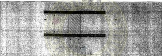
Q=TiL
Where, T=Kb
- T is called coefficient of transmissibility.
- We know that coefficient of permeability is defined as the discharge through unit area under unit hydraulic gradient. However in reality ground water travels through entire thickness oef aquifer (b)
- Hence coefficient of transmissibility is defined to find out the discharge. (Co-efferent of transmissibility is thus defined as, discharge per unit length of aquifer)
- T has a unit of length2 /time.
- Storage coefficient (S) and transmissibility coefficient (T) are known a formation constants of an aquifer and plays an important role in the unsteady flow through porous media.
- Storage coefficient and transmissibility or transmissivity is determined in the field by carrying out pumping test on wells and measuring the discharge and lowering of water levels in the observation wells.
STRATIFICATION:
- Sometimes the aquifers may be stratified with different permeability’s in each stratum. Two kinds of flow situations are possible in such a case.
(1) When the flow is parallel to the stratification, equivalent permeability K, of the entire aquifer thickness,
D = Di is
Ke = ki Di/Di
The transmissivity of the formation is
T = Ki Di
(2) When the flow is normal to the stratification the equivalent permeability Ke of the aquifer of length
L = Li is
Ke = Ki/(Li /Ki )
The transmissivity of the aquifer is T= Ke B.
EQUATION OF MOTION:
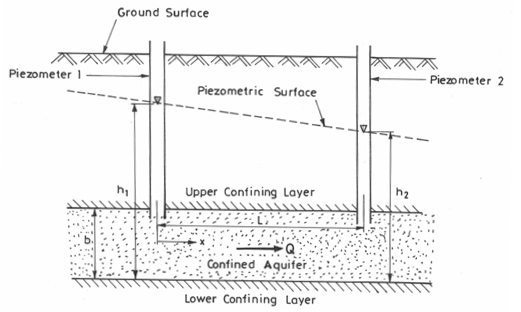
(1)One dimensional. Confined ground water low between two water bodies (confined flow)
Following assumptions are made in this analysis:
A) Aquifer is homogeneous and isotropic.
B) Flow is steady,

q = K (-dh/dx) D×1= discharge per unit width
Integration (0 to L) q dx = -kD integration (ho to h1) dh
QL = -K (h1-ho)D
q = KD (h0-h1)/L
Shape of water surface profile
q = K(-dh/dx)D×1
Integration q dx =- KD Integration dh
Qx = -KDh +C
At X=0,. h=ho
C = Kadhi
Qx = -KD(h- ho)
At X=L, h=h1
Qx/qL = -KD(h-ho)/-KD(h1-ho)
X/L = h-ho/h1-ho
h = ho + x/L (h1-ho)
In case of confíned flow between two reservoirs hydraulic grade line varies
Unconfined ground water flow between two water bodies (unconfined flow
Discharge per unit width inside =q
q = + K (-dh/dx)×h×1
Integration (o to L)q dx /K. = Integration (ho to h1). Hdh
QL/K = -[(h12 -ho2)/2]
q = K(ho2 - h12)/2L
For shape of water surface profile
Integration qdx /K = - integration hdh
Qx/K = - h2/2. +C
At x=0 , h=h0
At x=L, h =h1
Qx/K = h02 -h2 /2 And
QL/K = h02- h12/2
X/L = h02 -h2 /ho2- h12
h2 = h02 - (h02 -h12 )(x/L)
Water surface is a parabola in case of unconfined aquifer.
One Dimensional flow with recharge.
Where, R =recharge at constant rate of R m3 /s per unit horizontal area due to infiltration from the top of aquifer
q + Rdx = q+ dq
Dq/dx = R
q = -Kh dh/dx
= -k/2 d(h2)/dx
= -k/2 d/dx [d(h2)/dx]
= -k/2 . d2 h2 /dx2
R = -k/2 d2 h2 /dx2
d2 (h2)/dx2 = -2R/K
By integrating twice
h2 = - (2R/K).(x2/2)+C1x+c2
The boundary conditions are
At x= 0, h=h0 , C2 =h02
At x= L, h=h1 , c1 = -[h02 -h12-(2L2/k)]/L
h2 = -Rx2/K - [(ho2 -h12 -RL2/K)/L]x +h02
Thus water surface is in the form of ellipse
The water table will rise above h0 will reach a max elevation at a distance a and then falls back to h1 at X=L
The location of max water surface elevation is given by dh/dx =0
a = L/2-[k/R((h02-h12)/2L)]
The location x=a is called ground water divide
Flow to the left of divide will be towards left side water body and to the right of divide will be towards downstream water body equation for discharge at a distance x from UIS water body is given by
qx = -Kh (dh/dx)
qx =R(x-L/2)+K/2L(h02 -h12)
q0 =-RL/2 + K/2L(ho2 -h12)
qL =-RL/2+K/2L (ho2 -h12)
qL = q0 +RL
TILE DRAIN PROBLEM:
- The provision of Tile drain system is used to drain waterlogged areas, the objective being to reduce the level of the water table. Let us provide a set of tile drain as shown in the figure below and let there is a uniform recharge 'R.
- An approximate expression to the water table profile can be obtained from the formula a as discussed earlier by neglecting the depth of water in the drain h0 =h1 =0. The water table profile will then be
h2 = R/K (L-x)x

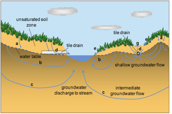

- The maximum height of the water table occur at a =L/2 and is of magnitude
hm =L/2 √(R/K)
- Considering a set of drain, since the flow is steady, the discharge entering a drain per unit length of the drain is
q = 2[R/(L/2)]. = RL
WELLS:
- Wells form the most important mode of groundwater extraction from an aquifer. While wells are used in a number of different applications, they find extensive use in water supply and irrigation engineering practice.
- For an unconfined Aquifer, prior to the pumping, the water level in the well indicates the static water table. A lowering of this water level takes place on pumping. If the aquifer is homogeneous and isotropic and the water table horizontal initially, due to the radial fowl into the well through the aquifer, the water table assumes a conical shape called cone of depression.
- The drop in the water table elevation at any point from its previous static level is called drawdown.
- The areal extent of the cone of depression is called area of influence and its radial extent radius of influence. At constant rate of pumping, the drawdown curve develops gradually with time due to the withdrawal of water from storage. This phase is called unsteady flow as the water table elevation at a given location near the well changes with time.
- On prolonged pumping, an equilibrium state is reached between the rate of pumping and the rate of inflow of groundwater from-the-outer edges-of the-zone of influence. The drawdown surface attains a constant position with respect to time when the well is known to operate under steady-flow conditions.
- As soon as the pumping is stopped, the depleted storage in the cone of depression is made good by groundwater inflow into the zone of influence. There is a gradual accumulation of storage till the original (static) level is reached. This stage is called recuperation or recovery and is an unsteady phenomenon.
- Changes similar to the above take place due to pumping of a well in a confined aquifer, but with the difference that, it is the piezometric surface instead of the water table that undergoes drawdown with the development of the cone of depression.
- In confined aquifers with considerable piezometric head, the recovery into the well takes place at a very rapid rate.
Steady Confined Flow (Fully Penetrating Well):
- Full penetrating well means the well which penetrates up to the bottom of the aquifer so that flow is more or less radial
- At a radial distance r from the well, if h is the piezometric head, the velocity of flow by Darcy's law is
Vr =K dh/dr
- The cylindrical surface through which this velocity occurs is 2πrB. Hence
Q = (2πrB)[K(dh/Dr)]
Q/2πrB (dr/r ) =dh
- Integrating between limits r1 and r2 with the corresponding piezometric head being h1 and h2 respectively.
Q/2πKB (In r2/r1) = (h2 -h1 )
Q = 2πKB (h2 -h1 )/[(In r2/r1)]
- This is the equilibrium equation for the steady flow in confined aquifer. This equation is popularly known as Thiem's equation.
- Further, at the edge of the zone of influence, s=0 ,r2 =R and h2 =H, at the well wall r1 =rw, h1 =hw and s1 =Sw.Hence
Q = 2πKBSw/In (R/rw )
- This is called Dupit's formula.
Steady Unconfined Flow:
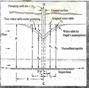
Vr= K(dh/dr)
Q=(2πrh)Vr = 2πrKh (dh/dr)
(Q/2πK)(dr/r) =h dh
- Integrating between limits r1 and r2 where the water-table depths are h1 and h2 respectively and on rearranging
Q = πK(h22 -h12)/(In r2/r1)
- This is the equilibrium equation for a well in an unconfined Aquifer (Thiems formula). As at the edge of the zone of influence of radius R, H= saturated thickness of the Aquifer Hence
Q = πK(H2-hw2)/In (R/rw)
- R is normally between 300-500 m.
Where hm = depth of water in the pumping well of radius rw.
NON EOUIABRIUM FORMULA FOR CONFINED AQUIFERS (UNSTEADY RADIAL FLOWS):
- The main drawback of the equilibrium formula given by Thiem and Dupit, was the problem to attain equilibrium conditions, which is not an easy to do The pumping has to be continued at a uniform rate for a very long time, so as to achieve steady flow conditions.
- Hence we adopt non-equilibrium formula as per this
s = Q/4πT [loge (4Tt/r2S)-0.5772]
= Q/4πT ×(well function)
Whereas Drawdown in thepbralion well after a time t. s7 Well function
Where,s =Drawdown in the observation well after a time t.
T = Coefficient of transmissibility.
Q = constant discharge pumped out from the well.
S = coefficient of storage of measured drawdown.
r = Radial distance of the observation well from the main pumped well.
If in an observation well at a distance r the drawdown are respectively s1 and s2 at time t1 and t2 after the pumping was started in the main well, then
S2 -S1 = Q/4πT loge (t2/t1)
INTERFERENCE AMONG WELLS:
- When two well, situated near to each other, are discharging, their drawdown curves intersect within their radius of zero drawdown. Thus, though the total discharge is increased, the discharge in individual well is decreased due to interference
- Figure blow shows interference between two well. If the two wells are a distance B apart, and have the same diameter and drawdown and discharge over the same period of time, it can be shown with the help of method of complex variables that the discharge through each well is given by
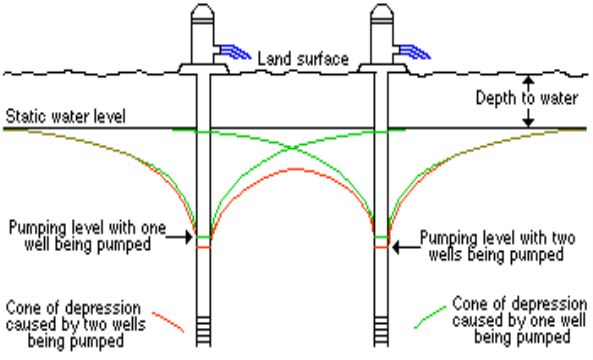
Q1 = Q2 -2πkb(H-h)/loge (R2/rB2)
Where R is the radius of area of influence (R>> B.)
Similarly if there are three wells forming an equilateral triangle a distance B on a side, and if all the three wells have the same characteristics
Then. Q1 =Q2 =Q3 =2πkb(H-h)/loge (R3/rB2)
WELL LOSS:
- In a pumping artesian well, the total draw down at the well Sw can be considered to be made up of three parts:
1. Head drop required to cause lamina porous media flow, called formation loss, wsL
2. Drop of piezometric head required to in turbulent flow in the region nearest to the well where the Reynolds number may be larger than unity, Swt and
3. Head loss through the well screen and casing, SwcOf these three,
SwL is directly proportional to Q
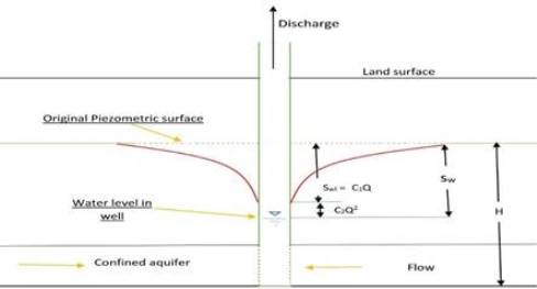
And (Swt and Swc ) directly proportional to Q2
Thus Sw = C1Q +C2Q2 =total loss
While the first term C1Q is the formation loss the second terms C2Q2 is termed well loss.
The magnitude of a well loss has an important bearing on the pump efficiency. Abnormally high value of well loss indicates clogging of well screens etc. and requires immediate remedial action.
Specific Capacity:
The specific capacity of a well is defined as the well yield per unit of drawdown.
Sp. Capacity = discharge of well/drawdown
= Q/ (C1Q+C2Q2)
= 1/ (C1 +C2Q)
The equation clearly shows that the sp. Capacity of the Wells is not constant but decreases as the discharge increases.
Safe Yield:
The maximum rate at which the withdrawal of ground water in a basin can be carried without producing undesirable results is termed safe yield. The "undesirable results include (1) permanent lowering of the groundwater table or piezometric head, (2) maximum drawdown exceeding a preset limit leading to inefficient operation of wells and (2) salt-water encroachment in a costal aquifer depending upon what undesirable effects is to be avoided, a safe yield far a basin can be identified.
AQUIFER TEST:
Although the pumping test gives accurate value of safe yield, it sometimes becomes very difficult to adjust the rate of pumping, so as to keep the well water level constant. In such circumstances recuperation test is adopted.
In this method, the water is first of all drained from the well at a fast rate so as to cause sufficient drawdown. The pumping is then stopped. The water level in the well will start rinsing. The time taken by the water to come back to its normal level or some other measured level is then noted. This discharge can then be worked out as below:
AB = Static water level in the well before the pumping was started.
CD = Water level in the well when the pumping was stopped.
S1 =depression head in the well at the time the pumping was stopped.
EF= Water level in the well at the noted time (say after a time T from when the pumping is stopped).
S2 =separation head in the well at time T after the pumping is stopped.
Let X-X is the position of water level at any time t after the pumping was stopped, and let the corresponding depression head be s. Let ds be the decrease in depression head in a time dt after the time t. Hence in a time t after the pumping is stopped, the water Level recuperates by (s1-s). It again recuperate by ds in a time dt after this.
Therefore Volume of water entering the well in the small interval of time (dt)
DV = A.dt......................(1)
Where A is the cross-sectional area of the well at the bottom.
Also, if Q is the rate of recharge into the well at the time t under a depression head s,then the volume of water entering the well in this small time interval is
=dV =Q dt
But, Q directly proportional to s
Q = Cs...............................(2)
Where C is a constant depending on the soil through which the water enters the well.
DV = Cs dt .............................(3)
Equating (1) and (3), we get
-Ads = Cs dt
(The-ve sign indicates that s decreases as t increase)
Or. Cdt /A = - (ds/s)
Integrating between the limits
t=0,. s=s1
t=T,. s=s2
We get,
C/A integrating (0to t)dt = - integrating (S1 to s2) ds/s
C/A (t)oT = -(loge)s1s2
C/A (T) = -loge s2/s1
= -2.3 log10 s2/S1
= 2.3 log10 s1/s2
C/A = 2.3/T (log10 s1/s2)
Knowing the values of s1, s2 and T from the above test, the value of C/A can be calculated C is called the specific capacity of the open well. Knowing the value of C/A, the discharge Q for a well under a constant depression head H can be calculated as follows:
Q = C s
Or. Q = (C/A) A.s
Or Q = [2.3/T log10 (s1/s2)] A.s
A and s are known, the discharge for any amounts of drawdown(s) can be easily worked out.