Unit-1
Deformation and Strain covering description of finite deformation
On application of an external force, the material of the structure undergoes changes in dimensions. This causes the member to change shape, which maybe temporary or permanent depending on the amount of force applied. This change in dimensions and shape is called as deformation.
The ratio of change in dimensions to original dimensions is called as Strain.
It is a dimensionless quantity.
The finite deformation maybe expressed with the help of 3 principal stretches, namely λ1, λ2, and λ3. For an incompressible material, the condition is
λ1λ2λ3 = 1 (1)
|
The isotropic material’s elastic properties are given by W(λ1, λ2, λ3) which is strain-energy function per unit volume.
Here, W depends on stretches from (1) above.
This deformation produces stresses in the material which are Cauchy’s principal stresses and are given as
|
Here, p is hydrostatic pressure acting.
If we consider two of the stresses independent and strain energy as a function of these,
|
Infinitesimal strain theory considers the deformation of body on a very minute scale. It is assumed that the body dimensions are unchanged due to deformation. Though this sounds strange, consider a care passing over a bridge. It exerts force on the bridge which causes some deformation of the bridge. But the bridge dimensions remain effectively unchanged due to this when the entire bridge is considered.
However, as an engineer, it is still important for us to find the effect of this car passing over the bridge. In this case, infinitesimal theory is used.
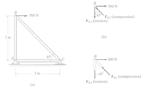
First of all, we have to determine whether the truss is determinate or not.
If, n = number of members
& j = number of joints
Then, n = 2j – 3.
If the above equation is satisfied, then the truss is determinate.
Methods of analysis of determinate trusses
- Methods of Joints
|
Procedure
- Consider any one joint and draw the FBD. The joint should have at least one known and maximum 2 unknown forces.
- Note down the equation of equilibrium by considering suitable X-Y axes and applying ΣFx and ΣFy.
- Identify zero force members.
- Repeat the procedure for each joint and find all the unknown forces.
2. Method of Sections
This method is useful when forces in only some members of the truss are to be found.
Procedure
- Draw FBD of the truss.
- Find the external reactions.
- Divide the truss with an imaginary section such that section passes through maximum three unknown forces.
- Draw FBD of any one side of the section. Always try to go with the side having lesser number of forces.
- Assume directions of the unknown forces.
- Form equations of equilibrium by taking moment about the point of intersection of forces.
- Repeat the procedure till all the unknown forces are found.
Modes of Failure
- By overturning about the toe
- By crushing
- By development of tension which leads to crushing
- By sliding that results in shear failure.
Criteria for Structural Stability of Dams
- The most important criteria to make sure that the failure doesn’t occur in the dam is
Pmin = ∑ (V / B) [ 1 - (6 e / B)] should be maximum zero.
Where, e = Eccentricity of the resultant force from the centre of the base,
∑ V=Total Vertical force,
B= Base Width
If Pmin is zero, then solving the above equation, we get e = B/6.
Stability Analysis
Stability Analysis by Gravity Method or Two-Dimensional Analysis
Assumptions
- The dam is assumed to be composed of a number of Cantilever structures, each 1 m thick and acting independent of each other.
- No load transfers to the abutments through beam.
- The foundation and the dam behave as a single unit.
- The material used in construction is isotropic and homogeneous.
- The stresses developed are isotropic and homogeneous.
- No movements of structure due to Transfers of loads.
Stability Analysis Procedure
Two-dimensional analysis can be carried out analytically or graphically
(a) Analytical Method
• Consider unit length of the dam
• Find all the vertical forces acting on the dam and their algebraic sum i.e. ∑ V
• Similarly, find all the horizontal forces and their algebraic sum, i.e. ∑ H
• Determine the moment of all these forces about the toe of dam.
• Find out the location of the resultant force by determining its distance from the toe.
• X= ∑ M / ∑ V
• Find out the eccentricity (e) of the resultant R using (B / 2) - X
• It must be less than B/6 in order to ensure that no tension is developed anywhere in the dam
• Determine the vertical stresses at the toe and heel i.e. ∑ (V / B) [ 1 - (6 e / B)] = 0
• Determine the maximum normal Stresses. At no point the stresses should exceed the permissible values.
Stability Analysis
Graphical method
• In this method, the entire dam section is divided into smaller horizontal sections of suitable length.
• For each section, the sum of the vertical forces ∑V and the sum of all the horizontal forces ∑ H acting above that particular section, are worked out and the resultant is drawn, graphically
• Repeat this for each section. Draw a line joining all the points where individual resultants are cut. This is the resultant force and should be located within the middle third to avoid any tension.
Following criteria must be satisfied for the stability of retaining walls:
- The wall must be strong enough to withstand lateral pressure.
- The wall must be safe against sliding.
- Weight of the wall and the earth pressure should be less than the bearing capacity of the soil it is constructed on.
- The inside diameter of the top of the chimney is decided by the value of minimum escape velocity of discharge gases at top.
- As the chimney height increases, the width must also increase to ensure stability. This is given by a standard table.
Width of chimney for stability
Height of Chimney in Meters | 1.00 | 1.25 | 1.50 | 1.75 | 2.00 | 2.25 | 2.50 | 2.75 | 3.00 | 3.25 | 3.50 | 3.75 | 4.00 | 4.25 | 4.50 |
Minimum width in Meters | 0.44 | 0.44 | 0.44 | 0.44 | 0.44 | 0.50 | 0.55 | 0.61 | 0.67 | 0.72 | 0.78 | 0.83 | 0.89 | 0.94 | 1 |
Practical construction in Brick Lengths | 2 | 2 | 2 | 2 | 2 |
|
| 3 | 3 |
|
| 4 | 4 |
|
|
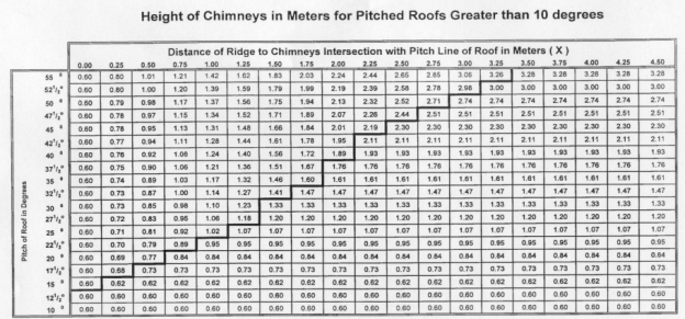
3. Chimneys must be 1m above openable roof lights. The height of a chimney H, should not be more than 4.5 times its minimum width W.
4. The pitch of a roof, and the distance from the ridge to the chimney's intersection with the pitched roof. The height of the chimney is then determined by the requirements.
|
Stress analysis of Thin Cylinders:
A cylinder is classified as thin cylinder if thickness to inner radius ratio is less than or equal to 1 / 10.
If thickness of the cylinder wall is less than 1/20th of the internal diameter ‘di’, the variation of the tangential stresses through the wall thickness is small & the radial stresses may be neglected.
|
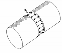
The stress produced in the longitudinal direction is σL and in the circumferential direction is σc These are called the longitudinal and circumferential stresses respectively.
Assume that the forces are trying to split the cylinder about its circumference as shown in above figure.
If the wall thickness is small as compared to the diameter, then
F = pA = p πD2 / 4 (1)
This force is balanced by the stress in the wall. The force due to the stress is
F = σL πDt (2)
Equating both the equations,
σL = pD / 4t (3)
Considering forces acting along the length of the cylinder,
F = p LD (4)
This force is balanced by the stress in the wall. The force due to the stress is
F = σc 2 Lt (5)
Equating both the equations,
σc = p D / 2t
This shows that for a given value of pressure, the circumferential stresses are double the longitudinal stresses developed in thin cylinders.
Stress analysis of Thick Cylinders:
A cylinder is classified as thick cylinder if thickness to inner radius ratio is greater than 1/10.
There are three types of stresses to be considered in the analysis.
- Stress along the circumferential direction.
- Radial stress.
- Longitudinal stress parallel to the axis of the cylinder.
Lame’s theory is used to analyze the stresses.
Consider a small section of the wall
Figure 6
We have 3 stresses in mutually perpendicular directions, the corresponding strains are
|
Consider the forces acting on a section of the wall
(σr + dσr)(r + dr)dθ - σr x r dθ = 2 σH x dr x sin (dθ/2)
Ignoring the second order terms and for small angles, sin (dθ/2) = dθ/2
r dσr + σr dr = σHdr
σr + r dσr / dr = σH
σH - σr = r dσr / dr (A)
Assuming that there is no modification in the structure due to strain
ƐL = (1/E) (σL - µ{σr + σH})
σr + σH = 2A = constant
Put in (A)

Multiplying through by r and rearranging

i.e 
Therefore integrating, 

And from eqn (b)

The above equation gives the values of longitudinal and radial stresses if constants A and B can be computed.
References:
1. Norris, C.H. and Wilber, J. B. and Utku, S. “Elementary Structural Analysis” Mc Graw Hill, Tokyo, Japan.
2. Timoshenko, S. and Young, D. H., “Elements of Strength of Materials”, DVNC, New York, USA.
3. Kazmi, S. M. A., ‘Solid Mechanics” TMH, Delhi, India.
4. Hibbeler, R. C. Mechanics of Materials. 6th ed. East Rutherford, NJ: Pearson Prentice Hall, 2004
5. Crandall, S. H., N. C. Dahl, and T. J. Lardner. An Introduction to the Mechanics of Solids. 2nd ed. New York, NY: McGraw Hill, 1979
6. Gere, J. M., and S. P. Timoshenko. Mechanics of Materials. 5th ed. Boston: PWS Kent Publishing, 1970.
7. Ashby, M. F., and D. R. H. Jones. Engineering Materials, An Introduction to their Properties and Applications. 2nd ed. Butterworth Heinemann.
8. Collins, J. A. Failure of Materials in Mechanical Design. 2nd ed. John Wiley & Sons, 1993.
9. Courtney, T. H. Mechanical Behavior of Materials. McGraw-Hill, 1990.
10. Hertzberg, R. W. Deformation and Fracture Mechanics of Engineering Materials. 4th ed. John Wiley & Sons, 1996.
11. Nash, W. A. Strength of Materials. 3d ed. Schaum's Outline Series, McGraw-Hill, 1994.


