Unit-4
Mechanics of Force-deformation relationships and static indeterminacy of deformable bodies
Steps to the principles of deformable body mechanics
(i) Study of forces and requirements for equilibrium
(ii) The study of deformation and geometric fit conditions
(iii)Application of relationships of force-deformation
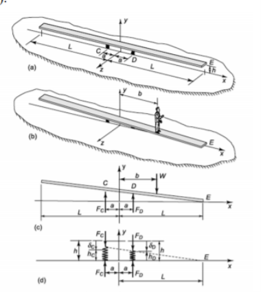
Suppose a man steps up to the center of the plank and slowly begins to walk toward one end. Before one end of the plank touches the ground, we should like to know how far he can walk; that is, estimate the distance b in Fig, when the right end E of the plank is just in contact with the ground (with two similar springs of spring constant K.
|
).
4.1.1 Assumption
(i) The rigid body of the wood plank is
(ii) Neglect the weight of the plank itself
4.1.2 Equilibrium
|
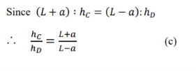
4.1.3 Geometry
From eqs. (a)~(e)
From eqs. (a),(b),(e), eliminate 𝐹C, 𝐹D
In case b > a, C spring is under the tension
|
4.2.1 Uniaxial loading
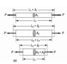
The deformation of three rods of the same material, but of different lengths and cross-sectional areas, as shown in Fig.
|
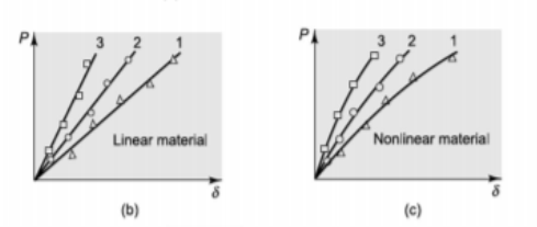
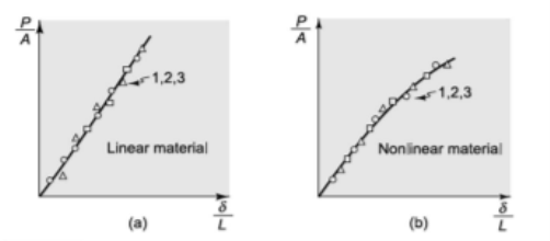
Assume that the load is gradually increased from zero for each bar and a measurement is made of the elongation at several load values.
- Assume that a tiny fraction of the bar length is the maximum elongation. A plot like Fig. will represent the outcomes of the three tests. 2.5(b) or something like Fig. 2.55 (c).
|
- The test results for the three bars can be represented by a single curve, as shown in Fig. Plotting load over area (stress) as ordinate and elongation over original length (strain) as abscissa, (a) or, (a) (b).
4.2.2 Hooke’s law
If the material's uniaxial load-elongation relationship is linear,
About the slope in Fig. (a) is referred to as the elasticity modulus and is generally denoted by the symbol E.
|
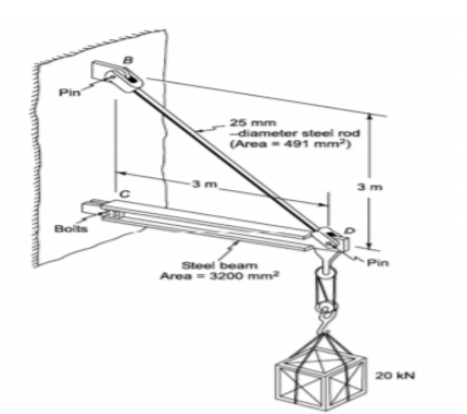
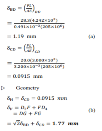
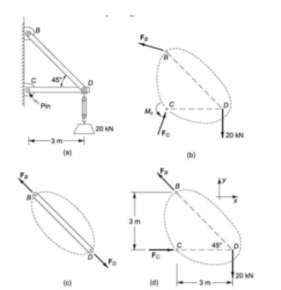
For the 20 kN load carried by the chain hoist, estimate the displacement at point D.
Supposition
(i) The bolted connection in C is treated as a pinned joint without friction.
In the deformed equilibrium configuration, the equilibrium demands of the first step should be met.
|
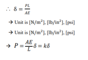
4.2.3 Force-deformation relation
|
- Example
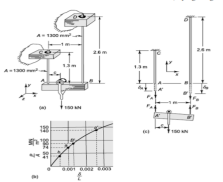
Find out where to locate the roller so that the beam in the deflected position will still be horizontal. We should also like to know whether if the load is increased from 150 kN to 300 kN, the place would be the same.
|
- Assumption
(i) Points A and B vertically deflect to A 'and B'.
(ii) The beam is regarded as rigid.
(iii) between the beam and the bars, there are no horizontal forces or couples acting
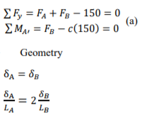
- Equilibrium
In order to determine the way in which the forces are distributed within the system, we must examine the deformation of the system.
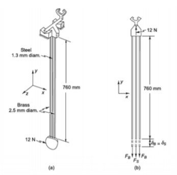
The pendulum of a clock that has a 12-N weight suspended by three 760 mm long rods is shown in figure (a). Two of the bars are made of brass, while the third is made of steel. We want to understand how much of the suspended 12-N weight is carried by each rod. Our system model is illustrated in Fig.
|
- Equilibrium
∑ 𝐹Y = 12 –𝐹S− 2𝐹B= 0
- Force-deformation relation
|
From Eq. (b) & (c)
- Example
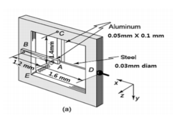
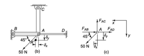
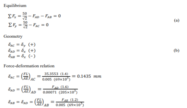
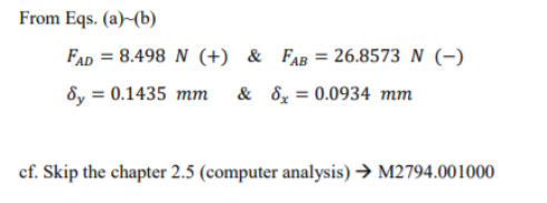
Figure (a) shows an instrument suspension consisting of two bars of aluminum and one rod of steel mounted in a rigid frame, together with an EA spring inclined to BA at 45°. The nut is tightened on the steel rod at D in the assembly so that there is no slack in the BAD line, and then the EA spring is installed with sufficient extension to generate a force of 50 N. We want to identify the deflection caused by the spring loading of the joint A (relative to the frame).
Assumption
(i) In comparison to aluminum bars and steel rods, the frame is essentially rigid.
(ii) Consider pinning the steel rod at point D
|
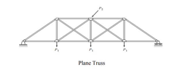
4.4.1 Plane Trusses
A truss is defined as an assemblage of straight members linked by flexible connections at their ends and subjected only to loads and reactions at the joints (connections). When the truss is loaded, the members of such an ideal truss develop only axial forces. The members are connected by bolted or welded connections in actual trusses, such as those commonly used to support roofs and bridges, which are not perfectly flexible, and the dead weights of the members are distributed along their lengths. Due to these and other deviations from idealized circumstances, some bending and shear is subject to truss members. These secondary bending moments and shears are, however, small compared to the primary axial forces in most trusses, and are usually not considered in their designs. If large bending moments and shears are anticipated, then the truss should be treated for analysis and design as a rigid framework (discussed subsequently). The truss is classified as a plane truss if all the members of a truss as well as the applied loads lie in a single plane. It is assumed that the plane truss members are connected by frictionless hinges. The analysis of plane trusses is much simpler than the analysis of space trusses (or three-dimensional trusses). Fortunately, many commonly used trusses for analysis can be treated as plane trusses, such as bridge and roof trusses.
|
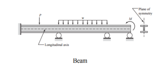
4.4.2 Beams
A beam is defined as a long straight structure perpendicular to its longitudinal axis that is loaded. Loads are typically applied in a plane of symmetry of the cross-section of the beam, causing only bending moments and shear forces to be exposed to its members.
|
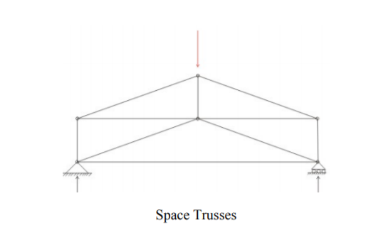
4.4.3 Space Trusses
Due to the arrangement of its members or applied loading, certain trusses (such as lattice domes, transmission towers, and certain aerospace structures cannot be treated as plane trusses. Such trusses are analyzed as three-dimensional structures subjected to three-dimensional force systems, referred to as space trusses. It is presumed that the members of space trusses are connected by frictionless ball-and-socket joints, and only at the joints are the trusses subject to loads and reactions. Like plane trusses, only axial forces develop within the members of space trusses.
|
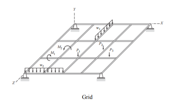
4.4.4 Grids
Like a plane frame, a grid is made up of straight members linked together to form a plane framework by rigid and/or flexible connections. The main difference between the two types of structures is that in the plane of the structure, plane frames are loaded, while grid loads are applied in the direction perpendicular to the plane of the structure. Therefore, in addition to the bending moments and the corresponding shears that cause the members to bend out of the plane of the structure, members of grids may be subjected to torsional moments. In such structures as sports arenas, auditoriums, and aircraft hangars, grids are commonly used for supporting roofs covering large column-free areas.
|
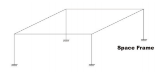
4.4.5 Space Frames
The most general category of framed structures constitutes space frames. Space frame members may be arranged in any arbitrary direction and linked by rigid and/or flexible links. Loads may be used on members as well as on joints in any direction. In general, the members of a space frame may be subjected to bending moments around both main axes, main-direction shears, torsional moments, and axial forces.
|
4.4.6 Statically Determinate and Indeterminate Trusses
The structure is an assemblage of a number of components that remain in equilibrium, such as slabs, beams, columns, walls, foundations, etc. For its existence, it must satisfy the fundamental criteria of strength, stiffness, economy, durability and compatibility.
For the stress resulting from bending moment, shear force, deflection, torsional stresses, and axial stresses, any structure is designed. If these moments, shears and stresses in different critical sections are evaluated, then the proportioning can be done on the basis of these.
Assessment of and plotting these stresses, moments and forces for that structural component is known as analysis. Determining and proportioning dimensions for these components of these stresses is known as design.
4.4.7 Determinate structures
These are only analyzed through the use of fundamental equilibrium equations. The unknown reactions are discovered for the further determination of stresses by this analysis. Simple support beams, cantilever beams, single and double overhanging beams, three hinged arches, etc. are examples of specific structures.
The one in which reactions and internal forces can be determined solely from free-body diagrams and equilibrium equations is a statically determined structure. These are the following equations: x H = 0, x V = 0 and x M = 0. It should be noted that the analytical results are independent of the material from which the structure was manufactured.
4.4.8 Principle of Superposition
1. In order for Hook's law to be valid, the material must behave in a linear-elastic way, and therefore the load is proportional to displacement.
2. Because of load application, the geometry of the structure must not undergo significant change, i.e., small displacement theory applies.
4.4.9 Determinacy and Stability
For any imaginable system of loads, a stable structure stays stable. Therefore, when deciding on the stability or determinacy of the structure, the types of loads, their numbers and their application points are not taken into account. A given structure that is externally considered determines whether the total number of reaction components is equal to the available equation of equilibrium. In other words, maybe.
- Example
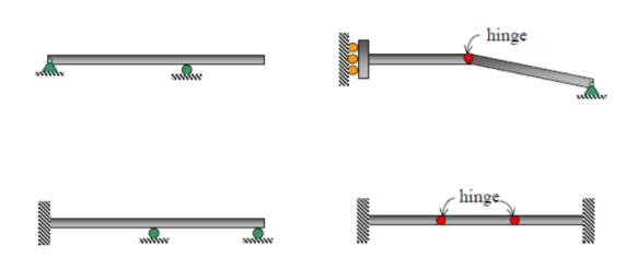
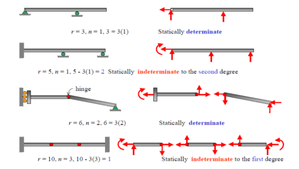
If each of the following beams is determined or indeterminate, classify. What is the number of degrees of indeterminacy when statically indeterminate?
|
- Solution
|
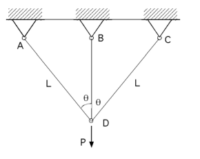
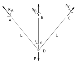
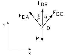
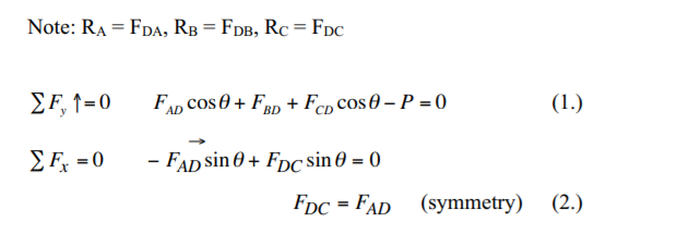
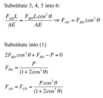
Can set up a problem to produce a set of simultaneous equations with unknown reactions and bar forces, but known displacements (compatibility at certain points) and known constitutive behaviors Can also use superposition and symmetry to simplify seemingly complicated problems (two pretty good principles). Since trusses are linear (i.e. the internal forces and deflections will also double if you double the load applied), in order to solve a problem, we can superimpose the effects of multiple force systems. The notion of deflection diagrams can be extended to more complex trusses - the basic principles remain the same: Symmetric 3 bar truss, bars cross sectional area A, Young’s modulus, E
cannot take moments - all forces pass through D
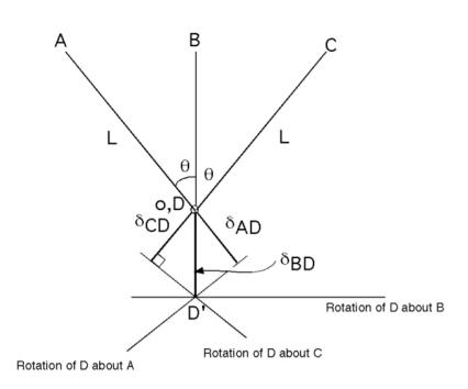
So must invoke compatibility bars extend and rotate, but remain attached at D: Displacement diagram
|
Reference:
1. Norris, C.H. and Wilber, J. B. and Utku, S. “Elementary Structural Analysis” Mc Graw Hill, Tokyo, Japan.
2. Timoshenko, S. and Young, D. H., “Elements of Strength of Materials”, DVNC, New
York, USA.
3. Kazmi, S. M. A., ‘Solid Mechanics” TMH, Delhi, India.
4. Hibbeler, R. C. Mechanics of Materials. 6th ed. East Rutherford, NJ: Pearson Prentice Hall, 2004
5. Crandall, S. H., N. C. Dahl, and T. J. Lardner. An Introduction to the Mechanics of
Solids. 2nd ed. New York, NY: McGraw Hill, 1979
6. Gere, J. M., and S. P. Timoshenko. Mechanics of Materials. 5th ed. Boston: PWS Kent Publishing, 1970.
7. Ashby, M. F., and D. R. H. Jones. Engineering Materials, An Introduction to their
Properties and Applications. 2nd ed. Butterworth Heinemann.
8. Collins, J. A. Failure of Materials in Mechanical Design. 2nd ed. John Wiley & Sons,
1993.
9. Courtney, T. H. Mechanical Behavior of Materials. McGraw-Hill, 1990.
10. Hertzberg, R. W. Deformation and Fracture Mechanics of Engineering Materials. 4th ed.John Wiley & Sons, 1996.
11. Nash, W. A. Strength of Materials. 3d ed. Schaum's Outline Series, McGraw-Hill,
1994.
