Unit- 5
Force-Stress-Equilibrium covering Multiaxial Stress and Strain
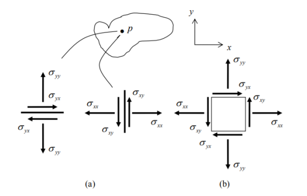
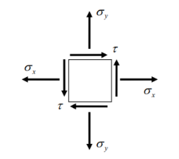
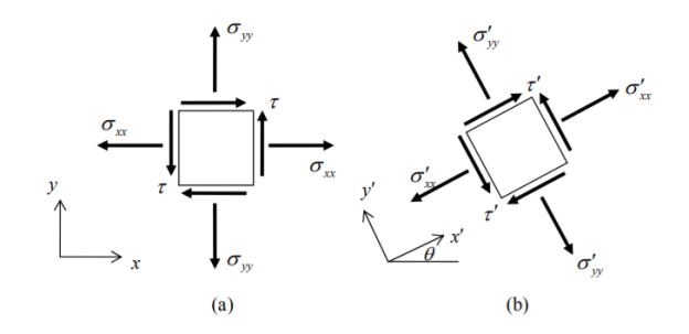
Consider the passage of two perpendicular planes through a point p. The components of stress acting on these planes are as shown in Fig. 1a. 1a. Together, these stresses are usually shown acting on a tiny finite-size material element, Fig.1b. The stress in a material has been seen to vary from point to point, but if the component is very small, the stresses on one side can be taken to be (more or less) equal to the stresses on the other side. By convention, all stress components shown are positive in analyses of the type that will follow.
|
Components of stress that act through a point on two perpendicular planes;
(a) two perpendicular surfaces at a point,
(b) a small material element at a point,
In the form of a stress matrix, the four stresses can conveniently be written:
|
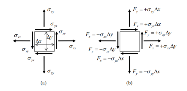
Stress components that act on two perpendicular planes through a point; (a) two perpendicular surfaces at a point, (b) a tiny material element at a point,
The four stresses can conveniently be written in the form of a stress matrix: The stresses shown are positive, but note how, depending on the definition of the x - y axes used, positive stresses can lead to negative forces. It is seen that the resulting force on the full component is zero.
|
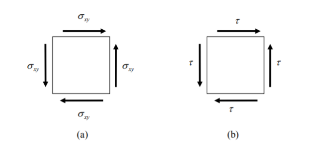
The shear stresses acting on the component are therefore all equal, and therefore the yx stresses are usually labeled xy, Fig, or simply marked Fig.
|
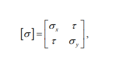
In fact, double-subscript notation is often dispensed with for simplicity in two-dimensional problems, and the stress matrix can be expressed as
|
To go with the representation illustrated in Fig.
|
Three-Dimensional Stress
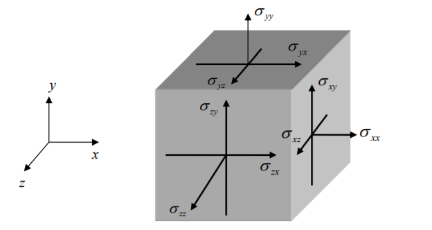
The three-dimensional equivalent of the two-dimensional component of Fig. is illustrated in Fig. Again, all of the stresses demonstrated are positive.
|
In this case, moment equilibrium means that
xy yxxzzxyz zy
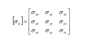
You can write the nine stress components in the matrix form, six of which are independent,
|
A vector F has one direction associated with it and three components of Fx Fy Fz characterize it. Stress is a quantity associated with two directions (the direction of a force and the normal direction of the plane on which the force operates) and characterized by the nine components of Eqn. A mathematical object like that is called a tensor. Just as with a change of coordinate axes, the three components of a vector change (for instance, as in Fig.), so the nine components of the stress tensor change with a change of axes. For the two-dimensional case, this is addressed in the next section.
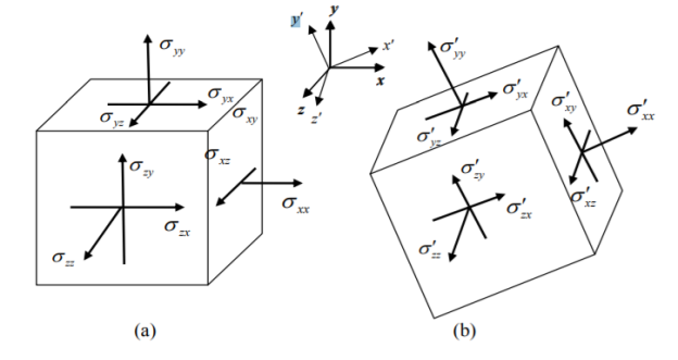
Consider the case in which the nine components of stress acting through a material particle on three perpendicular planes are known. When using x, y, z axes, these components are, xx xy x x, etc., and can be represented by the cube shown in Fig. Rotate the planes around the three axes now; the rotated cube shown in Fig. can represent these new planes.; the normal axes for the planes are now labeled x-y-z, and the corresponding stress components for these new axes are x-x-x-x-xy-x, etc.
|
A relationship exists between the components of stress, xx xy, etc., and the components of stress, xx x x xy, etc. Using Newton's Laws, the relation can be derived. In the fully three-dimensional case, the equations describing the relationship are very lengthy. The relationship will be derived here for the two-dimensional case-this 2D relationship will prove very helpful in analyzing many practical situations.
Two-dimensional Stress Transformation Equations
Assume that the components of stress from Fig. is well known. The stresses that arise on other planes must be found through p. Consider the planes of perpendicularity shown in Fig, obtained through a positive (counterclockwise) angle of rotation of the original element. The axes x to y are defined by the new surfaces
|
Cauchy stress
In previous modules, normal stress was expressed as a force per unit area acting perpendicular to a selected area, and shear stress was a force per unit area acting transversely to the area. Consider the situation depicted in Fig. to generalize this notion. 1, in which the traction vector T acts on an arbitrary plane within or at the body's outer boundary and in an arbitrary direction with regard to the plane's orientation. Traction is a simple force vector with magnitude and direction, but its magnitude is expressed per unit of area in terms of force:
|
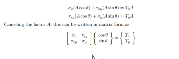
Where A is the magnitude of the region that F is acting on. The Cauchy1 stresses, which are a generalization of our previous stress definitions, are the forces acting on the Cartesian x, y, and z planes per unit area to balance the traction. This equilibrium can be written in two dimensions by drawing a simple free body diagram with the traction vector acting on an area of arbitrary size A (Fig. 2), remembering by multiplying the appropriate area to obtain the forces.
|
Material strength, also called material mechanics, deals with the behavior of solid objects subjected to stresses and strains. The theory began with the consideration of the behavior of structures' one and two-dimensional members, whose stress states can be approximated as two-dimensional, and then was generalized to three dimensions to develop a more complete theory of materials' elastic and plastic behavior. Stephen Timoshenko was an important pioneer in material mechanics.
The study of material strength often refers to different methods, such as beams, columns, and shafts, to calculate the stresses and strains in structural members. The methods used to predict the reaction of a structure under loading and its susceptibility to different modes of failure take into account the properties of the materials, such as their yield strength, ultimate strength, Young's module, and the ratio of Poisson. In addition, the macroscopic properties (geometric properties) of the mechanical element are considered, such as its length, width, thickness, boundary constraints and abrupt geometry changes such as holes.
Definition
The strength of a material in material mechanics is its ability to resist an applied load without failure or plastic deformation. The area of material strength deals with forces and deformations resulting from their action on a material. When those forces are expressed on a unit basis, a load applied to a mechanical member will induce internal forces within the member, called stresses. The stresses acting on the material cause the material to deform in different ways, including completely breaking it. When those deformations are also placed on a unit basis, the deformation of the material is called strain.
In order to evaluate the load capacity of that member, the stresses and strains which develop within a mechanical member must be calculated. This requires a complete description of the member's geometry, its limitations, the loads applied to the member and the material properties of which the member is composed. Axial (tensile or compressive) or rotational loads may be the loads applied (strength shear). The state of stress and state of strain at any point within the member can be calculated with a complete description of the loading and the geometry of the member. The strength (load carrying capacity) of that member, its deformation (stiffness characteristics), and its stability (ability to maintain its original configuration) can be calculated once the state of stress and strain within the member is known.
It is then possible to compare the calculated stresses to some measure of the strength of the member, such as its material yield or ultimate strength. The member's calculated deflection may be compared to the deflection criteria that are based on the use of the member. The member's calculated buckling load may be compared to the load applied. In order to calculate the dynamic response of the member, the calculated stiffness and mass distribution of the member can be used and then compared to the acoustic environment in which it will be used.
Types of loadings
- Transverse loadings: Forces applied perpendicular to a member's longitudinal axis. Transverse loading causes the member to bend and deflect from its original position, with the change in curvature of the member accompanied by internal tensile and compressive strains.
- Transverse loading also induces shear forces that cause the material's shear deformation and increase the member's transverse deflection.
- Axial loading- The forces applied are collinear with the member's longitudinal axis. The forces trigger either the member to stretch or shorten.
- Torsional loading- Twisting action caused by a pair of equal and oppositely directed externally applied force pairs acting on parallel planes or by a single external pair applied to a member with one end fixed against rotation.
Stress parameters for resistance
Several mechanical stress parameters can express material resistance. When referencing mechanical stress parameters, the term material strength is used. These are physical quantities with dimensions that are homogeneous per unit surface for pressure and force. Therefore, the traditional unit of strength measurement is MPa in the International System of Units and the psi between customary units of the United States. Yield strength, tensile strength, fatigue strength, crack resistance, and other parameters are parameters of strength.
Yield strength is the lowest stress in a material that generates a permanent deformation. The yield point is difficult to identify in some materials, such as aluminum alloys, so it is usually defined as the stress required to cause 0.2 percent plastic strain. This is called a stress of 0.2 percent proof.
Compressive strength is a compressive stress limit state that in the manner of ductile failure (infinite theoretical yield) or brittle failure (rupture as a result of crack propagation or sliding along a weak plane) leads to failure in a material
Tensile strength or ultimate tensile strength is a tensile stress limit state that results in tensile failure in the manner of ductile failure (yield as the first phase of that failure, some hardening in the second phase and breakage after possible formation of the 'neck') or brittle failure (sudden breaking in two or more pieces at a low-stress state). Tensile strength can be cited as either real stress or engineering stress, but the most commonly used is engineering stress.
Strength is a more complex measure of the strength of a material that takes into account several loading episodes during an object's service period,[6] and is usually more difficult to assess than the measurement of static strength. In the case of cyclic loading, it can be adequately expressed as an amplitude usually at zero mean stress, along with the number of cycles of failure under that stress condition. Fatigue strength is cited here as a simple range.
Impact strength is the material's capacity to withstand a load applied suddenly and is expressed in terms of energy. The Izod impact strength test or the Charpy impact test are often measured, both of which measure the impact energy needed to fracture a sample. The impact strength of a material is affected by volume, elasticity modulus, force distribution, and yield strength. In order to have a high impact strength of a material or object, the stresses must be evenly distributed throughout the object. It must also have a large volume with a low elasticity modulus and a high resistance to material yield.
Stress–strain relations
Elasticity is a material's ability to return to its previous shape after the release of stress. The relationship between applied stress is directly proportional to the resulting strain (up to a certain limit) in many materials, and a straight line is a graph representing those two quantities.
The slope of this line is referred to as the modulus of Young, or the "modulus of elasticity." The elasticity module can be used in the linear-elastic portion of the stress-strain curve to determine the stress-strain relationship. The linear-elastic region is either below the yield point, or if a yield point on the stress-strain plot is not easily identified, it is defined as between 0 and 0.2 percent strain and is defined as the strain region in which there is no yielding (permanent deformation) The reverse of elastic deformation is plasticity or plastic deformation and is characterized as an unrecoverable strain. Following the release of the applied stress, plastic deformation is retained. Most materials are normally capable of plastic deformation in the linear-elastic category. Brittle materials do not experience any plastic deformation, such as ceramics, and will fracture under relatively low strain, while ductile materials such as metallics, lead, or polymers will deform much more plastically before initiating a fracture. Consider the difference between chewed bubble gum and a carrot. Before breaking, the carrot will stretch very little. On the other hand, the chewed bubble gum will enormously deform plastically before finally breaking.
Reference:
1. Norris, C.H. and Wilber, J. B. and Utku, S. “Elementary Structural Analysis” Mc Graw Hill, Tokyo, Japan.
2. Timoshenko, S. and Young, D. H., “Elements of Strength of Materials”, DVNC, New
York, USA.
3. Kazmi, S. M. A., ‘Solid Mechanics” TMH, Delhi, India.
4. Hibbeler, R. C. Mechanics of Materials. 6th ed. East Rutherford, NJ: Pearson Prentice Hall, 2004
5. Crandall, S. H., N. C. Dahl, and T. J. Lardner. An Introduction to the Mechanics of
Solids. 2nd ed. New York, NY: McGraw Hill, 1979
6. Gere, J. M., and S. P. Timoshenko. Mechanics of Materials. 5th ed. Boston: PWS Kent Publishing, 1970.
7. Ashby, M. F., and D. R. H. Jones. Engineering Materials, An Introduction to their
Properties and Applications. 2nd ed. Butterworth Heinemann.
8. Collins, J. A. Failure of Materials in Mechanical Design. 2nd ed. John Wiley & Sons,
1993.
9. Courtney, T. H. Mechanical Behavior of Materials. McGraw-Hill, 1990.
10. Hertzberg, R. W. Deformation and Fracture Mechanics of Engineering Materials. 4th ed.John Wiley & Sons, 1996.
11. Nash, W. A. Strength of Materials. 3d ed. Schaum's Outline Series, McGraw-Hill,
1994.
