Objects deform when they are subject to external forces. These deformations can be major or slight, depending on the quality of the material and the stress involved. Strain is the quantification of the material deformation. The linear strain arises as a result of a difference in the length of the object. Linear strain is created by compressive or tensile stress. Shear strain occurs as a result of a change in the orientation of the object's molecules.
6.1.1 LINEAR STRAIN
As loading an object induces tensile or compressive stress inside the object, this stress is followed by some duration adjustment. This deformation can be measured in absolute terms that describe the change in length of the object as a result of the loading; for example, the rubber band stretched 10 cm or the intervertebral disc compressed 2 mm. The deformation may also be described in relative terms as a proportion of the change in length (the difference between the undeformed and the deformed lengths) divided by the original length (the undeformed length). This relative deformation measure is called linear strain. Mathematically, linear strain is defined as
|
where
ε = linear strain,
ℓ = stretched length,
ℓo = original, undeformed length, and
ℓ − ℓo = change in length.
6.1.2 Mechanical Behavior of Materials
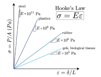
Clearly, stress and strain are related. Stress and strain are related by a constitutive law, and we can determine their relationship experimentally by measuring how much stress is required to stretch a material. This measurement can be done using a tensile test. In the simplest case, the more you pull on an object, the more it deforms, and for small values of strain this relationship is linear. This linear, elastic relationship between stress and strain is known as the Hooke Law. If you map stress versus strain, this graph will be linear for small strains, and the slope of the line will be the property of a substance known as a strain Young's Elastic Modulus. This value can vary greatly from 1 kPa for Jello to 100 GPa for steel. For most engineering materials, the linear region of the stress-strain diagram only occurs for very small strains (<0.1%). In this course, we will focus only on materials that are linear elastic (i.e. they follow Hooke's law) and isotropic (they behave the same no matter which direction you pull on them).
|
From Hooke's law and our definitions of stress and strain, we can easily get a simple relationship for the deformation of a material.
|
Intuitively, this exam makes a bit of sense: apply more load, get a larger deformation; apply the same load to a stiffer or thicker material, get less deformation. If the structure changes shape, or material, or is loaded differently at various points, then we can split up these multiple loadings using the principle of superposition.
|
A general deformation of a body can be expressed in the form x = F(X) where X is the reference position of material points in the body. Such a measure does not distinguish between rigid body motions (translations and rotations) and changes in shape (and size) of the body. A deformation has units of length.
|
where I is the identity tensor. As a result, strains are dimensionless and usually expressed as a decimal fraction, a percentage or part-per-notation. Strains measure how much deformation differs locally from rigid-body deformation.
In general, the strain is a tensor quantity. Physical insight into strains can be gained by observing that the strain can be decomposed into normal and shear components. The amount of stretching or compressing along material line elements or fibers is the normal strain, and the amount of distortion associated with sliding flat layers over each other is the shear strain within the deforming body. This could be applied by elongation, shortening, or changes in volume, or angular distortion.
6.2.2 Strain measures
Depending on the amount of strain, or local deformation, the analysis of deformation is subdivided into three deformation theories:
- Finite strain theory, also called large strain theory, large deformation theory, deals with deformations in which both rotations and strains are arbitrarily large. In this case, the undeformed and deformed configurations of the continuum are significantly different and a clear distinction has to be made between them. This is commonly the case with elastomers, plastically-deforming materials and other fluids and biological soft tissue.
- Infinitesimal strain theory, also called small strain theory, small deformation theory, small displacement theory, or small displacement-gradient theory where strains and rotations are both small. In this case, the body's undeformed and deformed configurations can be assumed to be the same. The infinitesimal strain theory is used in the analysis of deformations of materials exhibiting elastic behavior, such as materials found in mechanical and civil engineering applications, e.g. concrete and steel.
A change in the configuration of a continuum body results in a displacement. The displacement of a frame has components: a rigid-frame displacement and a deformation. A rigid-frame displacement includes a simultaneous translation and rotation of the frame without converting its form or length. Deformation implies the extrude in form and/or length of the frame from an preliminary or undeformed configuration κ0(B) to a cutting-edge or deformed configuration κt(B).
If after a displacement of the continuum there may be a relative displacement among debris, a deformation has occurred. On the opposite hand, if after displacement of the continuum the relative displacement among debris withinside the cutting-edge configuration is zero, then there may be no deformation and a rigid-frame displacement is stated to have occurred.
The vector joining the positions of a particle P in the undeformed configuration and deformed configuration is called the displacement vector u(X,t) = uiei in the Lagrangian description, or U(x,t) = UJEJ in the Eulerian description.
A displacement field is a vector field of all displacement vectors for all particles in the body, which relates the deformed configuration with the undeformed configuration. It is convenient to do the analysis of deformation or motion of a continuum body in terms of the displacement field. In general, the displacement field is expressed in terms of the material coordinates as
where αJi are the direction cosines between the material and spatial coordinate systems with unit vectors EJ and ei, respectively. Thus
and the relationship between ui and UJ is then given by
Knowing that
It is common to superimpose the coordinate systems for the undeformed and deformed configurations, which results in b = 0, and the direction cosines become Kronecker deltas
|
6.3.1 Normal Strain
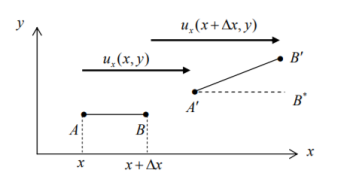
Consider a line element of length x emanating from position (x, y) and lying in the x - direction, denoted by AB in Fig.After deformation the line element occupies AB , having undergone a translation, extension and rotation.
|
The particle that was originally at x has undergone a displacement ux (x, y) and the other end of the line element has undergone a displacement ) ux (x, y x . By the definition of (small) normal strain,
|
In the limit x 0 one has
|
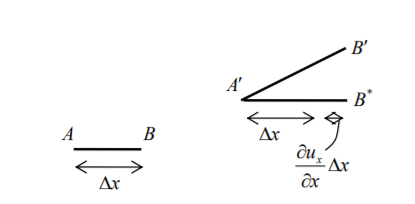
This partial derivative is a displacement gradient, a measure of how rapid the displacement changes through the material, and is the strain at (x, y). Physically, it represents the (approximate) unit change in length of a line element, as indicated in Fig
|
Similarly, by considering a line element initially lying in the y direction, the strain in the y direction can be expressed as
|
- A vector that represents a movement of a point in a body (due to applied loads) with respect to some reference system of axes
- Translation and/or rotation
- Shape and size of the body do not change
6.3.2 Multiaxial Stress-strain Relationships
- Structural analysis and design requires understanding of the system of the applied forces and the material behavior
- The behavior of a material can be studied by means of mechanical testing
- Stress vs. strain diagrams are more often used to describe the material behavior
- Stress vs. strain diagrams are supposedly/theoretically identical for the same material, but technically there is always some differences
Reference:
1. Norris, C.H. and Wilber, J. B. and Utku, S. “Elementary Structural Analysis” Mc Graw Hill, Tokyo, Japan.
2. Timoshenko, S. and Young, D. H., “Elements of Strength of Materials”, DVNC, New
York, USA.
3. Kazmi, S. M. A., ‘Solid Mechanics” TMH, Delhi, India.
4. Hibbeler, R. C. Mechanics of Materials. 6th ed. East Rutherford, NJ: Pearson Prentice Hall, 2004
5. Crandall, S. H., N. C. Dahl, and T. J. Lardner. An Introduction to the Mechanics of
Solids. 2nd ed. New York, NY: McGraw Hill, 1979
6. Gere, J. M., and S. P. Timoshenko. Mechanics of Materials. 5th ed. Boston: PWS Kent Publishing, 1970.
7. Ashby, M. F., and D. R. H. Jones. Engineering Materials, An Introduction to their
Properties and Applications. 2nd ed. Butterworth Heinemann.
8. Collins, J. A. Failure of Materials in Mechanical Design. 2nd ed. John Wiley & Sons,
1993.
9. Courtney, T. H. Mechanical Behavior of Materials. McGraw-Hill, 1990.
10. Hertzberg, R. W. Deformation and Fracture Mechanics of Engineering Materials. 4th ed.John Wiley & Sons, 1996.
11. Nash, W. A. Strength of Materials. 3d ed. Schaum's Outline Series, McGraw-Hill,
1994.


