Unit-7
Elasticity and Elasticity Bounds covering
The elastic modulus of the near surface region of a bulk test piece, or of the coating deposited on a substrate, can be obtained using depth-sensing hardness tests like the ultra-micro- and Nano hardness testers. The elastic modulus is obtained from the loading–unloading curve discussed earlier and shown in Fig. 2. The slope of the initial portion of the unloading curve equals the contact stiffness S (= dP /dh where P=load and h=depth of indentation). Once S is obtained as above and the contact area (A) between the indenter and the test piece is calculated on the basis of the known relationship between the indentation depth and contact area, the elastic modulus of the test material is obtained using the relation
|
In the above equation, Ei and νi represent the elastic modulus and Poisson’s ratio of the indenter material, respectively, while E and ν correspond to the elastic modulus and Poisson’s ratio of the test material. Since Ei and νi are known (especially for the commonly used indenter material, i.e., diamond), by assuming a reasonable value for the Poisson’s ratio of the test material (ν), The elastic module of the test substance can be computed. The indentation-based technique for estimating elastic modulus is particularly useful for estimating thin-coating.
Elasticity
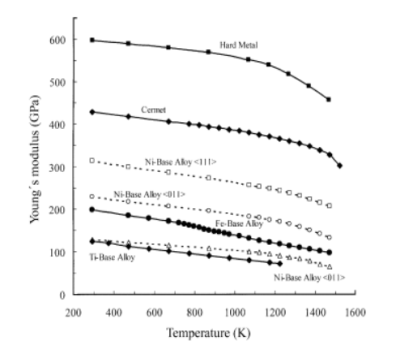
The elastic moduli, Young’s modulus E, and shear modulus G, describing the linearity between stress and strain in the elastic regime, differ a great deal for different material classes, composition, orientation, and temperature (Fig. 1). In particular, advanced high-temperature materials such as monocrystalline (SX) and directionally solidified (DS) nickel-base alloys show a clear orientation-dependence of the elastic moduli (Fig. 1). Thus, for anisotropic materials the E and G are no longer independent quantities and the elastic constants sij (compliances) or cij (stiffness’s) are required, their number being dependent on the lattice symmetry. For instance, single crystals with cubic, hexagonal, and orthorhombic symmetries have three, five, and nine, respectively, independent elastic constants cij or sij.
|
Elastic Properties
Elastic modulus is a global property that is essentially independent of the distribution of the reinforcement particles, but it depends on the consistency of the particle-matrix interface, which must have ample power to move the loading of the particle into the matrix. The measured values in the literature show a wide degree of scatter, which reflects different methods of measurement—dynamic measuring methods tend to give larger values than static measurements—and the quality of the composite. The quality of the composite will involve factors such as the interfacial strength, porosity, which is often associated with “unwet” particle clusters, and damaged particles. As noted above, particles may be fractured during processing, decreasing their ability to carry tension, which decreases the elastic modulus (Measurement of the elastic modulus has been used to track particle fractures with gradual deformation). The elastic modulus can also be affected by the presence of residual stresses in the composite, which are often generated during fabrication as a result of the coefficient of expansion mismatch between the alloy matrix and the reinforcing particles.
The simplest approach to representing the elastic modulus is the upper (KU) and lower (KL) bounds for the bulk modulus:
|
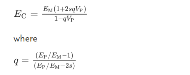
where the subscripts M and P refer to matrix and particle properties, respectively, VP is the volume fraction of reinforcing particles, and G is the shear modulus (see Composites, Physical Properties of). Young’s modulus, E, can be obtained using the standard relationship K=E/3(1−2ν), where ν is the Poisson’s ratio. These bounds are a quite broad, taking no account of particle shape, and Halpin (1984) used a micromechanics approach to take account of the particle aspect ratio:
|
EC is the Young’s modulus of the composite, and s is the particle aspect ratio, defined as the ratio of the largest to the smallest perpendicular particle cross-sectional radii.
An alternative approach, which also takes account of the particle shape and is to use the Eshelby equivalent inclusion method
The distinction between thin vs. thick wall pressure vessels is determined by the ratio between the mean radius of the vessel and the thickness of the wall. If this ratio is greater than 10, the vessel is considered a thin wall pressure vessel. If the ratio is less than 10, the vessel is considered a thick wall pressure vessel.
|
In operation, in a thin wall pressure vessel, stresses developed in the (thin) wall can conservatively be assumed to be uniform. These are the stresses students are familiar in calculating using ASME Section I PG-27 or Section VIII Div. I UG-27. In fact, most of the pressure vessels power engineers will work with are of a thin-wall type.
In contrast, a thick wall pressure vessel develops a greater (circumferential) stress on the inside surface of the vessel and it reduces towards the outside diameter. The design calculations for this type of vessels are only covered in the ASME Section VIII (Pressure Vessels) code, Mandatory Appendix 1 (Supplementary Design Formulas).
Development of stress formula in a pressure vessel
Circumferential stresses (longitudinal joints)
The circumferential stress (or hoop stress) acting on a longitudinal cross-section is derived in the textbook as:
|
Design problems most typically deal with finding the minimum required wall thickness, therefore the above formula is more useful expressed as:
|
Hoop stress formula from ASME Section VIII Div. 1 UG-27 is:
|
Efficiency “E” is the factor that accounts for loss of a material strength due to welds or ligaments. Also note that applying “-0.6P” to the denominator leads to a thicker shell compared to the theoretical formula, and therefore more conservative (or safer). Before using the formula check if the relation is applicable (thin wall).
ASME Section I (Power Boilers) calculates the shell thickness only based on circumferential stress, as follows:
|
The formulas are quite similar; in the above “y” is a temperature coefficient and C is an added allowance for corrosion or structural stability. Again, the coding formula leads to a thicker shell than merely by derivation.
Longitudinal stress (circumferential joints)
The Longitudinal stress demonstrated and derived in the textbook is derived as:
|
Note that longitudinal stresses are 50% of the hoop stresses and therefore they rarely govern the design. This is the reason ASME Section I does not even require evaluating this stress.
ASME Section VIII Div. 1 requires estimating the vessel thickness based on both stresses, and choosing the largest of the two values. Formula is:
|
Spherical pressure vessels
Spherical pressure vessel stress shall be measured in the same manner as longitudinal stress. You may conclude that a spherical pressure vessel will require a thinner shell, theoretically one half, than a cylindrical pressure vessel operating at the same pressure and temperature, and therefore it would be a preferred shape. The reality is that while most of that is true, it’s difficult to manufacture a spherical shell.
- Stress is a measure of the internal forces in a body between its constituent particles, as they resist separation, compression or sliding in response to externally applied forces.
- The mathematical definition of stress is defined as; the force exerted per unit area.
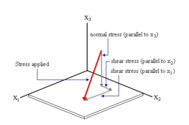
Stress on a plane
|
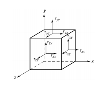
Stress at a point
|
TRANSFORMATION PRINCIPLES
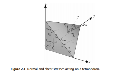
Consider the cube of Figure 1.2, and cut it in an arbitrary way such that the remaining part will form a tetrahedron. The reason for choosing a tetrahedron for this analysis is that a shape with four sides has the least number of planes to enclose a point. Figure 2.1 shows the stresses acting on the side and cut planes of the tetrahedron. The stress acting on the cut plane is denoted by S, which can be resolved into three components along the respective coordinate axes, assuming n defines the directional normal to the cut plane.
|
TWO-DIMENSIONAL STRESS TRANSFORMATION
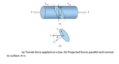
Figure 2.3 shows a steel bar under a tensile load F, where the tensile stress can simply be determined across the plane p-q, normal to the applied load. Although, this is an one-dimensional loading problem, the stress state is two-dimensional where a side load of zero actually exists. To develop an idea of coordinate transformation, we examine the stresses acting on plane m-n, which has an arbitrary orientation relative to the applied load.
|
The stress acting on plane p-q is simply expressed as:
|
Applying force balance on plane m-n will project the applied force F into the normal force FN and the shear force FS, i.e.:
|
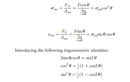
The resulting normal and shear stresses acting on plane m-n will be:
|
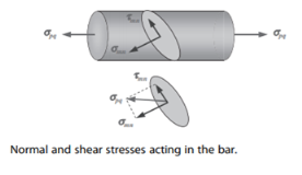
The above two stress components can therefore be simplified to (Figure 2.4):
|
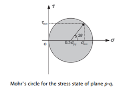
The relation between the normal and shear stresses can most easily be illustrated using Mohr’s Circle in which normal stress appears on the horizontal axis, shear stress corresponds to the vertical axis and the circle diameter extends to spq as shown in Figure 2.5. By rotating an imaginary plane, any combination of shear and normal stresses can be found. Mohr’s circle is used to determine the principal stresses, as well as for implementing failure analysis using Mohr-Coulomb criterion
|
STRESS TRANSFORMATION IN SPACE
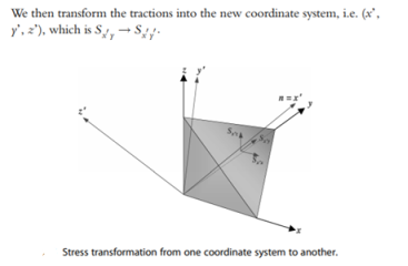
We have presented how the tractions are transformed using the same coordinate system. We’ll now develop the formulation for the stress transformation in a three-dimensional domain – from the coordinate system (x, y, z) to a new system (x’, y’, z’), as shown in Figure 2.6. The transformation is performed in the two stages. Firstly, the x’ axis is rotated to align with the cut plane normal n, and then the stress components are calculated (see Figure 2.6). The tractions for the element along the old coordinate axes, i.e. x, y and z can be written using the Cauchy’s transformation law as follows:
|
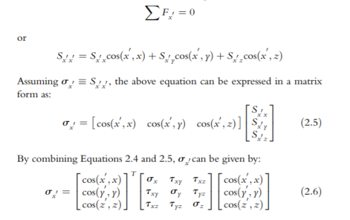
It can be noted that the Cauchy’s transformation law is somewhat similar to the transformation of the force components. Now the transformation of the area remains, which is carried out when the stresses related to the new coordinate system are found. Now Considering the equilibrium condition of the tetrahedron, and using Newton’s second law for the first stress component, we can derive
|
A failure is a breakdown of an object (such as metal, concrete or plastic) due to various factors that affect the strength, stability and chemical composition of the object's structure. Reasons for failure include:
- Corrosion
- Erosion
- Fatigue
- Stress corrosion cracking
- Cavitation
- Galling
- Fretting
- Foreign object damage
A metallurgical failure analysis is sometimes performed when a metal object fails. Metallurgists and engineers work to find the reasons and mechanisms that caused the failure in the material. In many cases corrosion and mechanical failure are found to be the primary reasons for failure.
Failures can be of two types
- Brittle failure - Brittle failure refers to the breakage of a material due to a sudden fracture. When a brittle failure occurs, the material breaks suddenly instead of deforming or straining under load. The fracturing or breaking can occur with only a small amount of load, impact force or shock.
- Ductile failure - A ductile failure is a type of failure seen in malleable materials characterized by extensive plastic deformation or necking. This occurs prior to the actual failure of the material. In ductile failure, there is absorption of massive amounts of energy and slow propagation before the fracture occurs.
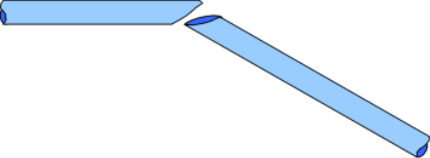
Fracture is the separation of a body into two or more pieces as a result of an imposed stress.
Fast fracture occurs when a pre-existing crack in a material suddenly becomes unstable and grows rapidly through the material. This form of fracture is highly undesirable. It is a catastrophic failure which occurs without warning.
|
The two most common failures to occur without warning are fast fracture and fatigue. Both fast fracture and fatigue cause failure below the nominal yield stress of a material. Fast fracture occurs through rapid propagation of a pre-existing crack leading to failure. Fatigue occurs through slow stepwise crack propagation under cyclic stresses with fast fracture occurring as a final step to failure.
In both fast fracture and fatigue, crack growth occurs from the presence of stress concentrations where there is a localized buildup of stress around the crack tip.
Ultimate failure occurs when the crack has a length greater than the critical crack length for which the material can support its load. At this point the crack advances rapidly through the material resulting in fracture.
Material failure theory is the science of predicting the conditions under which solid materials fail under the action of external loads. Failure of a material is generally known as brittle failure (fracture) or ductile failure (yield). Depending on the conditions (such as temperature, stress, loading rate) most materials can fail in a brittle or ductile manner or both. However, in most practical cases, a substance can be categorized as either brittle or ductile. Though failure theory has been in development for over 200 years, its level of acceptability is yet to reach that of continuum mechanics.
In mathematical terms, failure theory is articulated in the form of different failure parameters that are applicable for particular materials. Failure criteria are functions in stress or strain space which separate "failed" states from "unfiled" states. A precise physical definition of a "failed" state is not easily quantified and several working definitions are in use in the engineering community. Frequently, phenomenological failure parameters of the same type are used to estimate brittle failure and ductile yield.
Reference:
1. Norris, C.H. and Wilber, J. B. and Utku, S. “Elementary Structural Analysis” Mc Graw
Hill, Tokyo, Japan.
2. Timoshenko, S. and Young, D. H., “Elements of Strength of Materials”, DVNC, New
York, USA.
3. Kazmi, S. M. A., ‘Solid Mechanics” TMH, Delhi, India.
4. Hibbeler, R. C. Mechanics of Materials. 6th ed. East Rutherford, NJ: Pearson
Prentice Hall, 2004
5. Crandall, S. H., N. C. Dahl, and T. J. Lardner. An Introduction to the Mechanics of
Solids. 2nd ed. New York, NY: McGraw Hill, 1979
6. Gere, J. M., and S. P. Timoshenko. Mechanics of Materials. 5th ed. Boston: PWS
Kent Publishing, 1970.
7. Ashby, M. F., and D. R. H. Jones. Engineering Materials, An Introduction to their
Properties and Applications. 2nd ed. Butterworth Heinemann.
8. Collins, J. A. Failure of Materials in Mechanical Design. 2nd ed. John Wiley & Sons,1993.
9. Courtney, T. H. Mechanical Behavior of Materials. McGraw-Hill, 1990.
10. Hertzberg, R. W. Deformation and Fracture Mechanics of Engineering Materials. 4thed.John Wiley & Sons, 1996.
11. Nash, W. A. Strength of Materials. 3d ed. Schaum's Outline Series, McGraw-Hill,1994.

