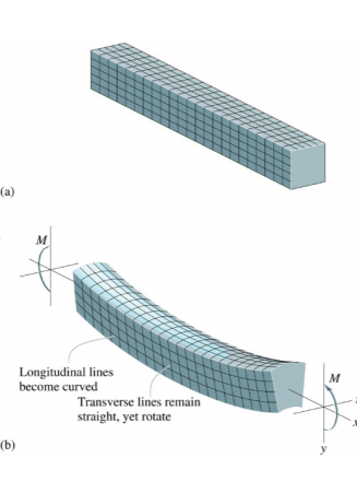
When lateral forces load a beam with a straight longitudinal axis, the axis is deformed into a curve, called the beam's deflection curve. The equations for finding the deflection curve are determined and the deflections are also found at specific
points along the beam axis.
|
Differential equations of the deflection curve.
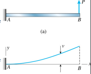
Consider a cantilever beam acting upward at the free end with a concentrated load. The axis of the beam deforms into a curve under the action of the load. At the fixed end of the beam, the reference axes have their origins. X to the right is positive and y upward is positive. The deflection v is the displacement of any point on the beam axis in the direction of y. As a function of the co-ordinate x, we must express v
|
We have to express v as a function of the co-ordinate x
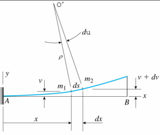
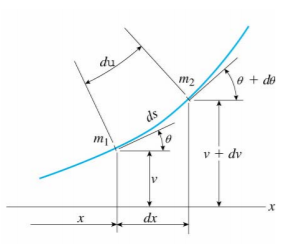
When the beam is bent, not only at each point along the axis, there is a deflection, but also a rotation. The angle of rotation of the beam axis (also known as inclination angle and slope angle) is the angle between the x-axis and the tangent to the curve of deflection.
|
|
The rotation angle is ⁇ for point m1 and ⁇ + δ ⁇ for point m2, i.e. δ ⁇ is the angle between the lines normal to the tangents at points m1 and m2. The center of curvature O 'is the point of intersection of these normals, and the distance O' to m1 is the curvature radius ¤
Beam Bending Strain
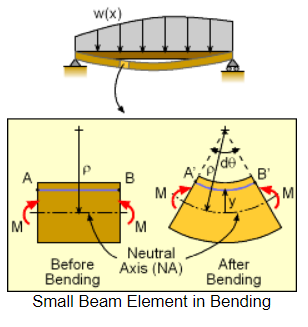
As shown in the diagram on the left, consider a small element cut from the beam to understand the bending stress in an arbitrary loaded beam. The derivation of the bending strain equation does not affect the beam type or actual loads. The basic definition of normal strain, recall, is
ε = ΔL/L
|
Using the line segment, AB, the before and after length can be used to give As shown in the diagram on the left, in order to understand the bending stress in an arbitrary loaded beam, consider a small element cut from the beam. The bending strain equation derivation does not affect the type of beam or actual loads. The basic definition, recall, of normal strain is Note that from the neutral axis, where there is no strain, the y coordinate is assumed upwards. Putting these together together gives,
|
This relationship provides the bending strain as a function of the curvature of the beam and the distance from the neutral axis at any place. This equation is of little use, however, and needs to be converted to stress. Also, at a given beam location, the curvature radius is difficult to determine.
Beam Bending Stress
σ = -Ey/ρ
There is still the problem of not knowing the curvature radius, civ. The radius of curvature and the moment of bending should be related if one thinks about it.
But there is still a radius of curvature, ε. But equation (1), equation = -Ey/σ, can be used again to remove ح, giving, giving,
E I /(-Ey/σ ) = M
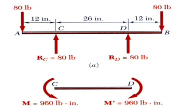
PU Equal and opposite couples acting in the same longitudinal plane were subjected to prism members
RE BENDING
|
• Excentric loading: axial loading that does not pass through the centroid section generates internal forces equivalent to an axial force and a few internal forces.
Transverse loading: concentrated or distributed transverse load generates internal forces equal to a shear force and a few internal forces.
• The principle of superposition: to find the complete state of stress, the normal stress due to pure bending can be combined with the normal stress due to axial loading and shear stress due to shear loading.
Symmetric Member in Pure Bending
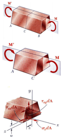
Internal forces are equivalent to a couple in any cross section. The couple's moment is the moment of section bending.
A couple M consists of two equal and opposite forces, from statics.
• The sum of the forces components in any direction is zero.
The moment is the same with any axis perpendicular to the couple's plane and zero with any axis included in the plane.
The moment is the same with any axis perpendicular to the couple's plane and zero with any axis included in the plane.
|
Curvature and Twist
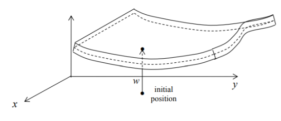
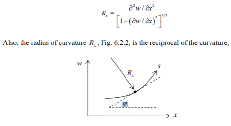
The plate is initially undeformed and flat with the mid-surface lying in the x-y plane. When deformed, the mid-surface occupies the surface w?? w(x, y) and w is the elevation above the plane of x - y, Fig.
|
The slopes of the plate along the x and y directions are w/ and x w/ y
Curvature
Recall from Book I, §7.4.11, that the curvature in the direction of x, x, is the rate of change of the angle of the slope in relation to the length of the arc s, Fig / . One discovers that
|
In terms of its deflection from its original unloaded position, the deformation of a beam is typically expressed. Deflection is measured from the beam's original neutral surface to the deformed beam's neutral surface. The configuration that the deformed neutral surface assumes is known as the beam's elastic curve.
Slope of a Beam: The angle between the deflected beam and the actual beam at the same point is the slope of the beam.
Deflection of Beam: Deflection is defined on a loaded beam as the vertical displacement of a point. In a section of a loaded beam, there are many methods to find out the slope and deflection.
Where the slope is zero, the maximum deflection happens. By equating the slope equation to zero, the position of the maximum deflection is determined. In the deflection equation, the value of x is then replaced to calculate the maximum deflection.
Methods of Beam Deflection Determination Numerous methods are available for beam deflection determination. Such techniques include:
Method for Double Integration:
- This is most appropriate when the beam is concentrated or udl over the entire length. A double method of integration is a powerful instrument at any point in solving a beam's deflection and slope because we will be able to get the elastic curve equation.
- A double integration technique is a powerful tool for solving a beam's deflection and slope at any point because we will be able to get the elastic curve equation.
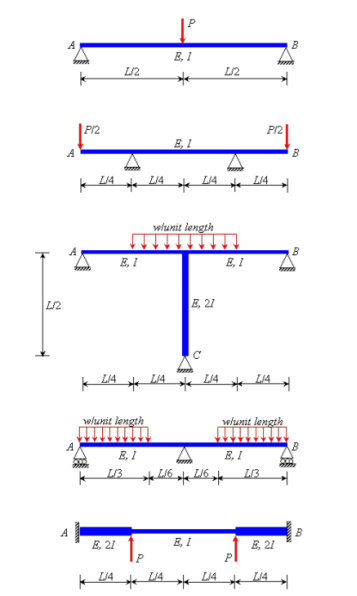
For the purpose of structural systems analysis, symmetry or antisymmetric in a structural system can be effectively exploited. In many real-life structural systems, symmetry and antisymmetric can be found in (or, in the idealized model of a real-life structural system). It is very important to remember that when we say symmetry in a structural system, both the structure itself, including the support conditions, and the loading on that structure imply the existence of symmetry. Systems that are shown in Fig. 1.15 is symmetric because the structure is symmetric for each individual case, and the loading is also symmetric. The systems, however, shown in Fig. They are not symmetrical because the structure or loading is not symmetrical either.
|
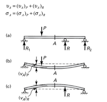
In the event of complicated load configurations, to simplify the analysis, the superposition method can be used to a good advantage. For instance, consider the continuous beam that is shown in Fig. This is then substituted by the beams shown in Fig.band c. The beam now experiences the deflections (a)p and (a)R because of P and R, respectively, at point A. The deflections and stresses are linear functions of transverse loadings, subject to the constraints imposed by small deformation theory and a material obeying Hooke's law, and superposition is valid:
|
For the analysis of statically indeterminate beams, using the principle of superposition, the moment area method and the conjugate beam method can be easily applied. Designate the excessive reactions as redundant and modify the support, depending on the degree of indeterminacy of the beam. The redundant reactions are then treated as forces which are unknown. The redundant reactions should be such that, along with the loads applied, they generate the compatible deformation at the initial support. Consider a supported cantilever beam, for instance, as shown in Figure 5.1. (a). As shown in Figure 5.1(b), let the reaction at B be R, which can be achieved with the compatibility condition that the downward vertical deflection of B due to the load applied (i.e. shown in Figure 5.1(c)) should be equal to the upward vertical deflection of B due to R (i.e. shown in Figure 5.1(c)) (d)
|
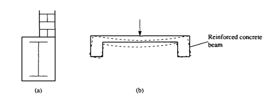
In general, torsion in beams arises from the action of shear loads whose application points do not coincide with the beam section's shear center. Hey. Ad. Examples of practical situations in which this happens are illustrated in Fig. From where, in Fig. An offset masonry wall supports a concrete enclosed I-section steel beam and Fig. As it deflects under load, a floor slab, cast integrally with its supporting reinforced concrete beams, causes torsion of the beams. Relevant codes of practice either imply or require the verification and provision of torsional stresses and deflections in design. Especially in the case of solid section beams and arbitrary shapes for which precise solutions do not exist, the solution to torsion problems is complex.
Empirical formulae are then used, which are conveniently expressed in terms of correction factors based on the geometry of a specific cross-section shape. The simplest case involving solid section beam torsion (as opposed to hollow cellular sections) is that of a shaft or bar of a circular section. Consequently, this case forms an instructive introduction to the more complex cases of solid section torsion, thin-walled open section and thin-walled closed section beams.
|
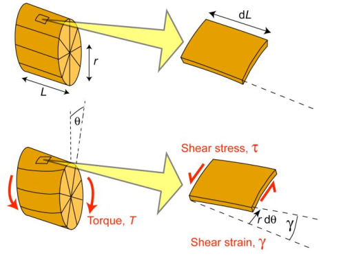
The twisting of a beam under the action of a torque is torsion (twisting moment). It is applied systematically to screws, nuts, axles, drive shafts, etc., and is also generated more randomly in car bodies, boat hulls, aircraft fuselages, bridges, springs, and many other structures and components under service conditions. A torque, T, has the same (N m) units as a moment of bending, M . Both are the result of strength and distance. The force is tangential in the case of a torque, and the distance is the radial distance between this tangent and the rotation axis.
|
The figure illustrates the torsion of a cylindrical bar. It can be seen that the shear strain in a bar component is given by the shear strain This equation applies, using the appropriate value of r, to the surface of the bar, as shown, and also to any other radial position. The shear strain obviously varies linearly with r, from zero at the center of the bar to a free surface peak value. At any radial location, the shear stress, i.e., is related to the shear strain by
Therefore, the torque, T-, can be written as
As for the case of beam bending, the geometric integral is represented as a second (polar) moment of area. For a solid w-diameter cylinder, this can be written as
The torque is thus given by
Comparing this equation with the equivalent one for beam bending M = E I K OK
|
The torsional analogue for the curvature of a bent beam can be seen to be the rate of twist along the bar's length. Although not quite so easily as a curvature, this can be measured experimentally (because the macroscopic shape of the bar does not actually change - at least when it is straight - see next page for an important example of a case when it is NOT straight).
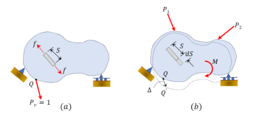
The method of virtual work, also known as the method of virtual force or unit-load method, uses the law of energy conservation to obtain the deflection and slope at a point in a structure. John Bernoulli developed this technique in 1717. Consider the deformable body shown in Fig., to illustrate the principle of virtual work. First, if a virtual or fictitious unit load Pv = 1 is applied at point Q, where a deflection parallel to the applied load is desired, an internal virtual or imaginary load f is created and a certain small amount is displaced by point Q. Then, putting on the same body the actual external loads P1, P2, and M will cause an internal deformation, dS, and an external deflection of point Q to Q 'by an amount of ⁇.
|
The point of application of the virtual load also shifts by ⁇ upon placement of the real load, and the applied unit load works by traveling the distance. The work carried out by virtual forces is as follows:
External work performed by the Pv load unit
|
Internal work accomplished through the virtual load
|
The following is suggested by applying the principle of energy conservation by equating equation 8.1 and equation 8.2:
External work completed = Internal work performed
|
where
Pv = 1 = external virtual unit load.
f = internal virtual load.
∆ = external displacement caused by real loads.
dS = internal deformation caused by real loads.
Similarly, in order to obtain a slope at a point on a structure, apply the virtual moment unit Mv at the specified point at which the slope is desired and apply the following equation derived from the energy conservation principle:
|
where
Mv = 1 = external virtual unit moment.
f = internal virtual load.
θ = external rotational displacement caused by real loads.
dS = internal deformation caused by real loads.
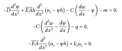
Consider the governing differential equations for the bending of the composite Timoshenko beam partial-interaction under uniformly distributed load and bending moment.
|
A trial variational principle can be constructed as follows using the semi-inverse technique.
Where is the Lagrangian Trial? There are many methods for constructing the Lagrangian trial; see [14-17]. We search for such a Lagrangian trial, so that one of the governing equations is provided with its Euler trial equation, an energy-like Lagrangian trial can be constructed as follows:
Variational Methods
Strain energy
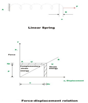
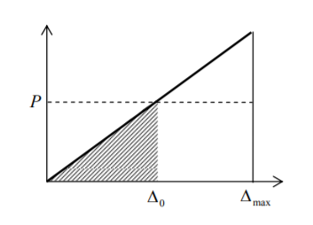
As shown in Fig.2.4, consider an elastic spring. It deflects by a small amount when the spring is pulled slowly. It goes back to its original position when the load is removed from the spring. It does some work when the spring is pulled by a force, and once the load-displacement relationship is known, this can be calculated. It can be noted that the spring is a mathematical idealization of the axial pulling of the rod by a force of 1 u P. It is assumed here that the force is gradually applied so that it increases slowly from zero to a maximum P value. Such a load, as there are no inertial effects due to motion, is called static loading. As shown in Fig., let the load-displacement relationship be 2.5.—2.5. The work performed by the external force can now be calculated as
|
The region enclosed by the force-displacement curve gives the total work performed by the load applied externally. It is assumed here that the energy is preserved, i.e. the work carried out by loads gradually applied is equal to the energy stored in the structure. This internal energy is known as energy from strain. Now the energy of strain stored in a spring is
|
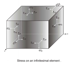
The same units express work and energy. The unit of work and energy in the SI system is the joule (J), which equals one Newton meter (N.m). The strain energy can also be defined as the internal work performed by the stress that results in the corresponding deformations moving through. Within a three dimensional homogeneous and isotropic material, consider an infinitesimal element. The state of stress acting on such an element may, in the most general case, be as shown in Fig. 2.6.—2.6. The component is affected by normal stresses (σx, and σσ y z) and shear stresses (Vortxyyzzx, and σσ y z). We have standard and shear strains corresponding to normal and shear stresses. Strain power can now be written as
|
Elastic
Consider the case of an instantaneous weight P dropping to the end of an elastic bar. The strain energy stored at the final force P and the final displacement 0 would be 2 0 1 P if the weight P had been applied gradually from zero. Throughout the deformation, however, the instantaneously applied load is constant and work done up to a displacement 0 is P0, Fig. 8.2.14. 14.10. The difference between the two implies that kinetic energy is acquired by the bar (see Eqn. 8.1.19); during compression, the material particles accelerate from their equilibrium positions. Since the deformation goes beyond 0, it is obvious from Fig. 8.2.14 that the strain energy is increasing faster than the weight work, and so there must be a decrease in kinetic energy; the particles are beginning to slow down. Finally, at A max ⁇ 2A0, the work performed by the weight is exactly equal to the stored strain energy and the material is at rest.
The material, however, is not in balance-the equilibrium position for a load P is A0-and thus the material begins to accelerate back to A0.
|
The bar and weight will continue to indefinitely oscillate between 0 and ⁇ max. Internal friction in a real (inelastic) material will cause the vibration to decay. Thus, under impact loading, the maximum compression of a bar is twice that of a bar gradually exposed to the same load.
Complementary and total strain energy
Strain Energy: - Due to deformation, strain energy is defined as the energy stored in a body. The strain energy per unit volume is referred to as the density of strain energy and the area under the stress-strain curve towards the deformation point. The whole system returns to its original shape when the applied force is released.
Complimentary Energy: - The complementary strain energy is called the area enclosed by the inclined line and the vertical axis. The complementary strain energy and elastic strain energy are the same for linear elastic materials.
Once again, beam bending provides a convenient starting point for the discussion of the simulation using dislocation dynamics of permanent plastic deformation and residual stresses.
Let there be N dislocations distributed within a residually bent beam with Burgers' vectors b Fig. The total shift deficit to one side will be Nb, bending angle Nb/h, and curvature k = Nb/hL = pbb. Therefore, the expression for bent beam curvature is given by the value = k/b, where the value = N/hL is used to denote the density of dislocations that are geometrically necessary.
This term (due to Ashby) is reserved for dislocations that result in the creation of strain gradient collectively, which is an accompanying feature of beam bending, as we note from previous discussions. As in the earlier illustration, the creation of a plastic strain gradient requires a preponderance of dislocations of a specific sign.
|
Statistically stored dislocations, on the other hand, are terms that refer to random sign dislocations that can accommodate plastic stretching or compression, but do not give rise to strain gradient.
Castigliano’s First Theorem
The complementary energy is equal to the strain energy for a linearly elastic structure where external forces only cause deformation. The first theorem of Castigliano can be stated for such structures as the first partial derivative of the strain energy of the structure with regard to any specific force gives the displacement of the point of application of that force in the direction of the line of action of the structure.
|
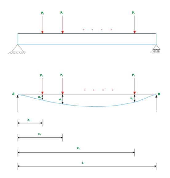
Let the forces acting on a simply supported beam of span 21 21 L be at the left end. Let the displacements be at the loading points, as shown in Fig. Now, assume that the material obeys Hooke's law and invokes the principle of superposition, the external forces' work is provided by the external forces.
|
In a conservative system, work performed by external forces is stored in the structure as strain energy. Hence, the structure's strain energy is,
It can be observed that the equation (3.7) at the loading point is nothing but displacement. 1 u In general terms,
|
Therefore, the partial derivative of the total strain energy with respect to any external load is equal to the displacement of the load application point in the direction of the applied load for the determined structure within the linear elastic range, provided the supports are unyielding and the temperature is maintained constant. This theorem is advantageously used for the calculation of elastic structure deflections. A few examples illustrate the procedure for calculating the deflection.
Maxwell Bettie’s reciprocal theorem
Virtual work and unit load method for deflection
A basic theorem in structural analysis is the Maxwell-Betti Law of real work. Using this theorem, the flexibility coefficients in compatibility equations, formulated by the flexibility method to solve indeterminate structures, will be determined to form a symmetric matrix, reducing the number of deflection computations. In the construction of influence-line diagrams for statically indeterminate structures, the Maxwell-Betti law also has applications. The Maxwell-Betti law, which applies on unyielding supports and at constant temperature to any stable elastic structure (for example, a beam, truss, or frame), states
|
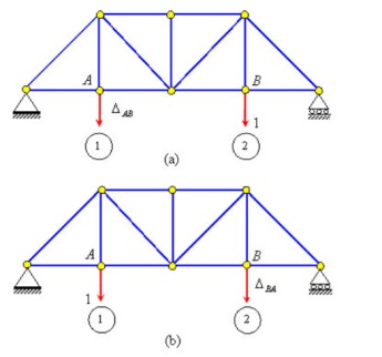
Consider the simple beams shown in the figure to prove the reciprocal theorem,
As shown in the figure, let a vertical force at point B produce a vertical deflection at point A and at point B (a). Similarly, in Figure (b), vertical deflection is produced by the application of vertical force at point A and at points A and B, respectively.
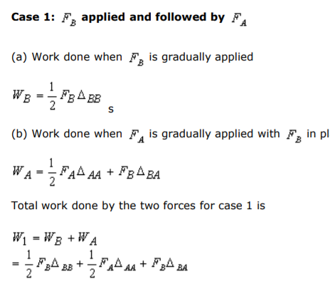
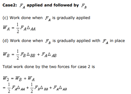
Let us evaluate the total work done by the two forces and when they are applied to their final value in a different order to the zero.
|
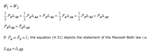
Since the final deflected beam position produced by the two load cases is the same, irrespective of the order in which the loads are applied. Regardless of the order in which the loads are applied, the total work performed by the forces is also the same. The total work of Cases 1 and 2 is thus equated with the total work of Cases 1 and 2.
|
In beams and frames, the Maxwell-Betti theorem also applies to rotations as well as rotation and linear movement.
Reference:
1. Norris, C.H. and Wilber, J. B. and Utku, S. “Elementary Structural Analysis” Mc Graw
Hill, Tokyo, Japan.
2. Timoshenko, S. and Young, D. H., “Elements of Strength of Materials”, DVNC, New
York, USA.
3. Kazmi, S. M. A., ‘Solid Mechanics” TMH, Delhi, India.
4. Hibbeler, R. C. Mechanics of Materials. 6th ed. East Rutherford, NJ: Pearson
Prentice Hall, 2004
5. Crandall, S. H., N. C. Dahl, and T. J. Lardner. An Introduction to the Mechanics of
Solids. 2nd ed. New York, NY: McGraw Hill, 1979
6. Gere, J. M., and S. P. Timoshenko. Mechanics of Materials. 5th ed. Boston: PWS
Kent Publishing, 1970.
7. Ashby, M. F., and D. R. H. Jones. Engineering Materials, An Introduction to their
Properties and Applications. 2nd ed. Butterworth Heinemann.
8. Collins, J. A. Failure of Materials in Mechanical Design. 2nd ed. John Wiley & Sons,1993.
9. Courtney, T. H. Mechanical Behavior of Materials. McGraw-Hill, 1990.
10. Hertzberg, R. W. Deformation and Fracture Mechanics of Engineering Materials. 4thed.John Wiley & Sons, 1996.
11. Nash, W. A. Strength of Materials. 3d ed. Schaum's Outline Series, McGraw-Hill,1994.
