Unit-9
Structural stability
We have formulated the condition of the static equilibrium of bodies and structures by studying the small change (variation) of the total potential energy. The system was said to be in equilibrium if the first variation of the total potential energy vanishes. The analysis did not say anything about the stability of equilibrium.
To illustrate the concept, consider a rigid body (a ball) siting in an axisymmetric paraboloid. shown in Fig.
|
In the case of a rigid body the total potential energy is just the potential energy Π = mgh = Cu2 where u is the horizontal displacement of the ball from the resting position.
Let’s calculate the first and second variation of the function
Π(u) δΠ = ∂Π /∂u δu = 2Cuδu
δ 2Π = δ(δΠ) = 2Cδuδu
At the origin of the coordinate system u = 0, so the first variation of Π is zero no matter what the sign of the coefficient C is. In the expression for the second variation, the product δuδu = (δu) 2 is always non-negative. Therefore, the sign of the second variation depends on the sign of the coefficient C.
From Fig. we infer that C > 0 corresponds to a stable configuration. The ball displaced by a small amount δu will return to the original position.
By contrast, for C < 0, the ball, when displaced by a tiny amount δu, will roll down and disappear. We call this an unstable behavior. The case C = 0 corresponds to the neutral equilibrium.
One can formalize the above consideration to the elastic body (structure), where the total potential energy is a function of a scalar parameter, such as a displacement amplitude u. The function Π(u) can be expanded in Taylor series around the reference point u0
|
For the system in equilibrium the first variation must be zero only. Therefore, to the second term expansion, the sign of the increment of Π depends upon the sign of the second variation of the potential energy. We can now distinguish three cases
|
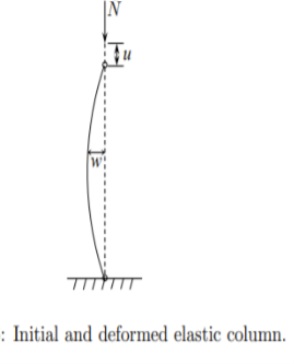
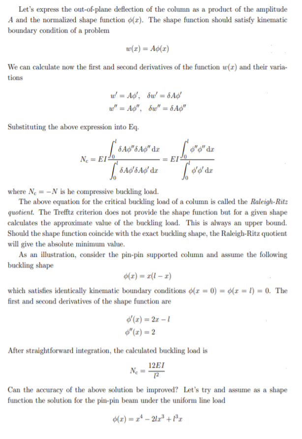
The Trefftz condition for stability can now be extended to the elastic column subjected to combined bending and compression. The elastic strain energy stored in the column is a sum of the bending and axial force contribution
|
It is assumed that the column is fixed at one end against axial motion and allow to move in the direction of the axial force.
|
To maintain generality, no static or kinematic boundary conditions are introduced in the present derivation. The work of external forces is W = Nu0
The first variation of the total potential energy is
|
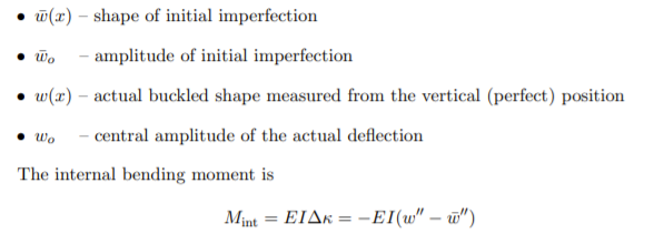
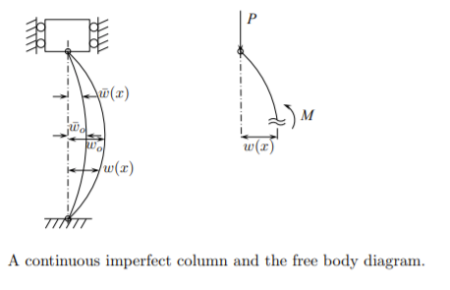
It’s interesting to note that with smaller and smaller initial imperfections, the equilibrium paths are approaching the bifurcation point but it never reach it. This type of behavior is same to all imperfect structures. As another example of an imperfect structure consider a pin-pin elastic column. The following notation is introduced:
|
Columns fail by buckling when their critical load is reached. Long columns can be analysed with the Euler column formula
F = n π2 E I / L2
where
F = allowable load (lb, N)
n = factor accounting for the end conditions
E = modulus of elastisity (lb/in2, Pa (N/m2))
L = length of column (in, m)
I = Moment of inertia (in4, m4)
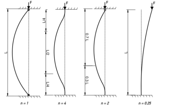
Factor Counting for End Conditions
|
- column pivoted in both ends: n = 1
- both ends fixed: n = 4
- one end fixed; the other end rounded: n = 2
- one end fixed; one end free: n = 0.25
Note!
Equation (1) is sometimes expressed with a k factor accounting for the end conditions:
F = π2 E I / (k L)2
where
k = (1 / n)1/2 factor accounting for the end conditions

Example - A Column Fixed in both Ends
A column with length 5 m is fixed in both ends. The column is made of an Aluminum I-beam 7 x 4 1/2 x 5.80 with a Moment of Inertia iy = 5.78 in4. The Modulus of Elasticity of aluminum is 69 GPa (69 109 Pa) and the factor for a column fixed in both ends is 4.
The Moment of Inertia can be converted to metric units like
Iy = 5.78 in4 (0.0254 m/in)4
= 241 10-8 m4
The Euler buckling load can then be calculated as
F = (4) π2 (69 109 Pa) (241 10-8 m4) / (5 m)2
= 262594 N
= 263 kN
Slenderness Ratio
The term "L/r" is known as the slenderness ratio. L is the length of the column and r is the radiation of gyration for the column.
- The higher slenderness ratio - lower critical stress to cause buckling
- The lower slenderness ratio - higher critical stress to cause buckling
- The slenderness ratios L/r < 40: "short columns" where failure mode is crushing (yielding)
- The slenderness ratios 40 < L/r < 120: "intermediate columns" where failure mode is a combination of crushing (yielding) and buckling
- The slenderness ratio of 120 < L/r < 200: "long columns" where failure mode is buckling
Mathematically, the effective length factor or the elastic K-factor is defined as follows:
|
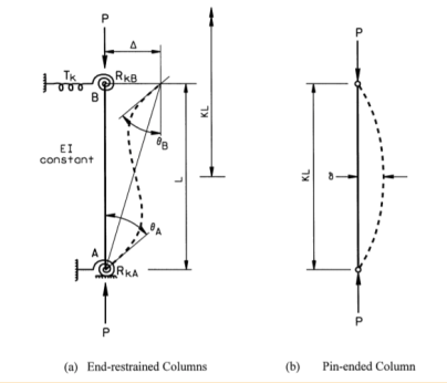
where Pe is the Euler load, the elastic buckling load of a pin-ended column; Pcr is the elastic buckling load of an end-restrained framed column; E is the modulus of elasticity; I is the moment of inertia in the flexural buckling plane; and L is the unsupported length of column. Physically, the K-factor is a factor that when multiplied by actual length of the end-restrained column (Figure) gives the length of an equivalent pin-ended column (Figure) whose buckling load is same as that of the end-restrained column. It follows that effective length, KL, of an end-restrained column is the length between adjacent inflection points of its pure flexural buckling shape. Specifications provide resistance equations for pin-ended columns, while the resistance of framed columns can be estimated through K-factor to the pin-ended columns strength equation. Theoretical K-factor is termed from an elastic eigenvalue analysis of the entire structural system, while practical methods for the K-factor are based on an elastic eigenvalue analysis of selected sub assemblages. The effective length concept is only tool currently available for the design of compression members in engineering structures, and it is most essential part of analysis procedures.
Columns are usually considered as vertical structural elements, but they can be positioned in any orientation (e.g. the diagonal and horizontal compression elements in a truss).
Columns are used as major elements in trusses, building frames, and sub-structure supports for bridges (e.g. piers).
• Columns support compressive loads from roofs, floors, or bridge decks.
• Columns transmit the vertical forces to the foundations and into the subsoil.
The work of a column is simpler than the work of a beam.
• The loads attached to a column are axial loads only.
• Column loads are usually added to the ends of the member, resulting in axial compressive stress.
• However, occasionally loads acting on a column can include axial forces, transverse forces and bending moments (e.g. beam-columns).
Columns are described by the length between the ends of the support.
• Short columns (e.g. footing piers).
• Long columns (e.g. bridge and freeway piers).
Virtually every common construction material is used for the column construction.
• Steel, timber, concrete (reinforced and pre-stressed), and masonry (brick, block, and stone).
The selection of a particular material may made based on the following.
• Strength (material) properties (e.g. steel vs. wood).
• Appearance (circular, square, or I-beam).
• Accommodate the connection of other members.
• Local production capabilities (i.e. the shape of the cross section).
Columns are major structural elements that greatly influence the overall efficiency and stability of the structure.
• Columns are built with higher protection ratios than other structural elements.
• The failure of the joist or beam may be localized and may not adversely damage the stability of the building; (e.g. there is redundancy with girders and beams, but not with columns).
• Failure to construct a strategic column can be disastrous for a wide section of the system.
• Failure may be attributed to overstress, loss of segment (deterioration), accident/sabotage (terrorism).
|
The theory of linear elasticity is useful for modelling materials which undergo small deformations, and which return to their original configuration upon removal of load. Almost all real materials will undergo some permanent deformation, which remains after removal of load. With metals, significant permanent deformations will usually occur when the stress reaches some critical value, called the yield stress, a material property. Elastic deformations are termed reversible; the energy expended in deformation is stored as elastic strain energy and is completely recovered upon load removal. Permanent deformations involve the dissipation of energy; such processes are termed irreversible, in the sense that the original state can be achieved only by the expenditure of more energy. The classical theory of plasticity grew out of the study of metals in the late nineteenth century. It concerns materials that initially deform elastically but deform plastically when yield stress is reached. In metals and other crystalline materials, the occurrence of plastic deformations at the micro-scale is due to the movement of dislocations and the migration of grain boundary at the micro-level. In sands and other granular materials plastic flow is due both to the irreversible rearrangement of individual particles and to the irreversible crushing of individual particles. Similarly, compression of bone to high stress levels will lead to particle crushing. The deformation of micro voids and the development of micro-cracks is also an important cause of plastic deformations in materials such as rocks. A good part of the discussion in what follows concerns the plasticity of metals; this is the 'simplest' type of plasticity and serves as a good background and an introduction to plasticity modeling in other material-types. There are two broad groups of problems with metal plasticity that are of interest to the engineer and analyst. The first involves relatively small plastic strains, often of the same order as the elastic strains which occur. Analysis of problems involving small plastic strains allows one to design structures optimally so that they do not fail when in service, but at the same time are not stronger than they really need to be. In this sense, plasticity is seen as a material failure1 . The second type of problem involves very large strains and deformations, so large that the elastic strains can be disregarded. These issues appear in the study of metal processing and formation procedures, which can include extrusion, drawing, welding, rolling and so on. In these latter-type problems, a simplified model known as perfect plasticity is usually used (see below) and special limit theorems which are used for such models are used.
Plastic deformations are usually rate-independent, that is, the stress caused is independent of the rate of deformation (or rate of loading). This is in marked contrast to classical Newtonian fluids for example, where the stress levels are governed by the rate of deformation through the viscosity of the fluid. Materials commonly known as “plastics” are not plastic in the sense described here. They, like other polymeric materials, exhibit viscoelastic behaviour where, as the name suggests, the material response has both elastic and viscous components. Due to their viscosity, their response is, unlike the plastic materials, rate-dependent. Further, although the viscoelastic materials can suffer irrecoverable deformation, they do not have any critical yield or threshold stress, which is the characteristic property of plastic behaviour. When a material undergoes plastic deformations, i.eIrrecoverable and at critical yield stress, and these results are rate-dependent, the substance is referred to as viscoelastic. Plasticity theory began with Tresca in 1864, when he conducted an experimental program on metal extrusion and published his famous yield criteria discussed later. Further advances with yield criteria and plastic flow rules were made in the years which followed by Saint-Venant, Levy, Von Mises, Hencky and Prandtl. The 1940s saw the advent of classical theory; Prager, Hill, Drucker and Koiter, among others, brought together many fundamental aspects of the theory into a single framework. The arrival of powerful computers in the 1980s and 1990s provided an impetus to further develop the theory, giving it a more rigorous foundation based on the thermodynamics principles, and brought with it the need to consider many numerical and computational aspects to the plasticity problem.
In order to check the stability of a structure at failure, we typically use the concept of Ultimate Limit State as defined in various codes (Eurocodes, AASHTO, SNIP, etc…). This state is often studied under an elastic hypothesis, and doesn’t take into account all nonlinear phenomena linked to failure: plasticity, cracking, damage, etc… When possible, a simplified approach used by engineers is to perform elastic studies mainly by using simple software programs or doing manual calculations. This seldom takes into account nonlinear aspects. Instead, safety is generally built in the computations by increasing loads and by curbing the limit strength of the materials, following rules provided in the codes. The drawback of this method is that it does not take into account the physical behavior of the structure. As said previously, failure is typically nonlinear and an elastic analysis, even when safety factors are included, does not account for the real physical behavior (displacements and stresses). Therefore, engineers have to perform elasto-plastic analysis. Not only can this take time in order to create the full 3D model, especially in the field of metallic beam connections, but this often leads to numerical problem of convergence, and complex interpretation of results. Another way to assess the failure state is by using the Limit Analysis theory.
By definition, Limit Analysis aims at studying a structure at its limits, meaning at failure, by assuming all materials have reached (and withstood) their limit strength criterion. The elastic behavior is therefore not included in the analysis; therefore no elasto-plastic iterations need to be performed. But the underlying assumption is that the materials allow high ductility deformations. The admissible stress values are limited by a given criterion. It’s usually defined by a function f, and a domain G such as: 𝜎 ∈ 𝐺 ⟺ 𝑓(𝜎) ≤ 0
As material criterion (or law), we can list few examples, which vary based on the model selected: - N c ≤ N ≤ Nt for a 1D beam model under normal force only, - M1 ≤ M ≤ M2 for a 1D beam model under one bending moment only , - Von Mises for 3D steel model, - Drucker-Prager for 3D soil model.
In a static approach and for a given external load F, we want to find the safety factor which leads to failure. To do so, we need to guess a first stress distribution which is in equilibrium with F. Then, we find the maximal multiplier , such that 1 withstands the given material criterion f( 1 ) ≤ 0. As only one stress distribution was analyzed, one does not know if it is the optimal distribution. Hence, we can only say that ≤ . By implementing this method with another distribution 2 , still in equilibrium with F, one gets a which can be higher or lower than 1 . By trying all admissible distributions in equilibrium with F, the static approach leads to the calculation of the maximum of all the multiplier i. And as we can’t try all mathematical possible distributions (infinite dimensional vector space), we find opt = max ( i) as a lower bound of . The output of this approach is a lower bound of the load multiplier and the corresponding stress distribution. The drawback is that we don’t know anything about the displacement field.
This theory is not widely used in civil engineering because of its main drawback: the engineer (or the software program) has to make a ‘guess’ on what the solution is likely to be: either a failure mechanism (by blocs for instance), or a stress distribution (as in strut-and-tie method). Most of the time we don’t know in advance the solution, so we need to try different solutions until finding the optimal one. As this can be very tricky, especially in case of complex structures, this theory has limited use (2D analysis or examples above) and will need careful review by senior engineers. In short, Limit Analysis is the research of an optimal solution either in stress distribution or in failure displacements. That is why we typically split this theory in two approaches: a static one and a kinematic one
Reference:
1. Norris, C.H. and Wilber, J. B. and Utku, S. “Elementary Structural Analysis” Mc Graw
Hill, Tokyo, Japan.
2. Timoshenko, S. and Young, D. H., “Elements of Strength of Materials”, DVNC, New
York, USA.
3. Kazmi, S. M. A., ‘Solid Mechanics” TMH, Delhi, India.
4. Hibbeler, R. C. Mechanics of Materials. 6th ed. East Rutherford, NJ: Pearson
Prentice Hall, 2004
5. Crandall, S. H., N. C. Dahl, and T. J. Lardner. An Introduction to the Mechanics of
Solids. 2nd ed. New York, NY: McGraw Hill, 1979
6. Gere, J. M., and S. P. Timoshenko. Mechanics of Materials. 5th ed. Boston: PWS
Kent Publishing, 1970.
7. Ashby, M. F., and D. R. H. Jones. Engineering Materials, An Introduction to their
Properties and Applications. 2nd ed. Butterworth Heinemann.
8. Collins, J. A. Failure of Materials in Mechanical Design. 2nd ed. John Wiley & Sons, 1993.
9. Courtney, T. H. Mechanical Behavior of Materials. McGraw-Hill, 1990.
10. Hertzberg, R. W. Deformation and Fracture Mechanics of Engineering Materials. 4th ed.John Wiley & Sons, 1996.
11. Nash, W. A. Strength of Materials. 3d ed. Schaum's Outline Series, McGraw-Hill, 1994.


