Module 2
Geometric Design of Highways
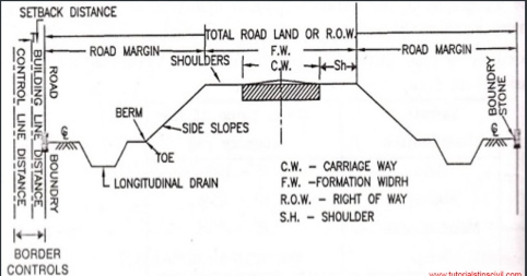
In order to obtain optimum efficiency of traffic operations ensuring maximum safety at reasonable cost, we design the geometrics of highway. Geometric Design of highways deals with the following elements:
- Cross-section elements
- Sight distance considerations
- Horizontal alignment details
- Vertical alignment details
- Intersection elements
Factors which govern the geometric elements are, as follows:
- Design speed
- Most important factor
- Decided on the basis of type of road such as NH, SH, MDR etc and topography of region
2. Topography
- Helps in deciding the design speed on different terrains:
a) Plain terrain (cross slope up to 10%) – 100 kmph
b) Rolling terrain (cross slope of 10% to 25%) – 30 kmph
c) Mountainous terrain (cross slope of 25% to 60%) – 50 kmph
3. Traffic factors
- Includes vehicular as well as human characteristics
4. Design hourly volume and capacity
- A reasonable value of traffic volume is use for design of highways as it is uneconomical to design road facilities for peak traffic flows
5. Environmental & other factors
- Includes aesthetics, landscaping, air & noise pollution etc.
- Friction
- Friction determines the operating speed and distance requirements in stopping & accelerating the vehicles.
- Skidding occurs in a vehicle when transverse movement of tyre > circumferential movement of tyre.
- Slipping occurs when circumferential movement of tyre > transverse movement of tyre.
- Factors affecting friction are:
Type & condition of pavement surface
Type & condition of tyre & tyre-pressure
Speed of vehicles
Temperature of tyre & pavement
- Coefficient of friction decreases with increase in temperature, load & tyre pressure.
- As per IRC,
Longitudinal friction coefficient = 0.35 to 0.40
Lateral friction coefficient = 0.15
- When a longitudinal friction coefficient of 0.40 is allowed for stopping a vehicle, the resultant retardation is 3.93m/s2, which is not too uncomfortable for passengers.
b. Pavement unevenness
- A Bump Integrator is used to measure vertical undulations of pavement surface recorded per unit horizontal length of the road.
- Unevenness index < 150 cm/km for good pavement surfaces of high speed highways
- Unevenness index = 250 cm/km is satisfactory for speed up to 100 km/hr
- Unevenness index = 350 cm/km is uncomfortable to passengers even at 50 km/hr
c. Camber/ cross-slope
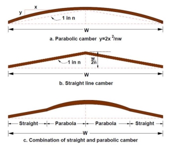
- Camber is the slope provided to the road surface in the transverse direction to drain off the rain water from the road surface.
- The requirement of camber depends upon:
- Type of pavement surface
- Amount of rainfall
- Shape of camber:
- Parabolic & elliptic – preferred by fast moving vehicles, because they require frequent crossing over the crown line during over-taking operations
- Straight line – to provide very flat cross slope in cement concrete pavements
- Note: Superior the road, flatter the camber (RCC > CC > Thick BT > Thin BT > WBM > Gravel > Earth).
Types of Road Surface | Camber | |
Heavy Rainfall | Light Rainfall | |
Cement concrete & high bituminous | 2% | 1.7% |
Thin bituminous | 2.5% | 2% |
WBM & gravel pavement | 3% | 2.5% |
Earth | 4% | 3% |
d. Width of Pavement/ carriageway
Considering that IRC recommends the maximum width of a vehicle to be 2.44m, the minimum width of pavement criteria is given as follows:
- Single Lane = 3.75m
- Two Lane (without kerb) = 7.0m
- Two Lane (with kerb) = 7.5m
- Intermediate Lane = 5.5m
- Multi-lane pavement = 3.5m/lane
- Width of single lane for village roads = 3m
e. Traffic separators/ medians
- As per IRC, minimum desirable width of 5m for medians of rural highways is recommended.
- It may be reduced to 3m where land is restricted.
- Width of median can be further reduced to 1.2 – 1.5m for long bridges.
- IRC Recommendations for Median Width:
At urban intersection = 1.2m
For vehicles making right turn = 4m to 7.5m
For vehicles crossing at grade = 9m to 12m
f. Kerb height
- A Kerb is the edging of a pavement (or a sidewalk) near a road. It indicates the boundary between the pavement and shoulder, or sometimes islands or footpath. The heights of different types of kerbs are:
Low-mountable = 10 cm
Semi-barrier = 15 cm
Barrier = 20 cm
Sight Distance is the length of road visible ahead to the driver at any point of time. There are 3 major types of Sight Distances considered by IRC, as discussed below:
a) Stopping Sight Distance (SSD)
- Also known as non-passing sight distance
- Depends upon the following factors:
Features of the road
Height of the driver’s eye above the road
Height of the object above the road
Total reaction time of the driver
Speed of vehicle
Efficiency of brakes
Friction
Gradient of the road, if any
- As per IRC,
height of eye level of driver above the road = 1.2m
height of object above road = 0.15m
- As per PIEV Theory, Total Reaction Time varies from 0.5 sec for simple situations to 4 sec in complex situations. It consists of:
Perception Time: time required by the driver to realize that brakes must be applied
Intellection Time: time required to understand the situation, based on skill and type of problem
Emotional Time: time elapsed during emotional sensation
Volition Time: time taken for final action
- SSD is the sum of the following distances:
Lag Distance - distance travelled by vehicle during total reaction time
Lag distance = v.t (v is speed of vehicle in m/sec)
= 0.278V.t (V is speed of vehicle in km/hr)
Where, t = total reaction time (sec) = 2.5 sec as per IRC
Braking Distance - distance travelled by vehicle after application of brakes
Brake distance =  (v is speed of vehicle in m/sec)
=  (V is speed of vehicle in km/hr)
Where, f = longitudinal friction coefficient (0.35 to 0.40)
g = acceleration due to gravity (9.81 m/s)
- Mathematically,
SSD = lag distance + brake distance
SSD = v.t +  (in meters)
SSD = 0.278V.t +  (in meters)
- Effect of Gradient:
SSD = v.t +  (in meters)
SSD = 0.278V.t +  (in meters)
Where, 𝜂 = braking efficiency
n = % gradient
Use + sign for ascending gradient.
Use – sign for descending gradient.
Where, f = longitudinal friction coefficient (0.35 to 0.40)
g = acceleration due to gravity (9.81 m/s)
- For 2-way single lane, minimum SSD = 2 x SSD
b) Safe Overtaking Sight Distance (OSD)
- Also known as safe passing sight distance
- Depends upon the following factors:
Speed of overtaking, overtaken & the vehicle coming from the opposite direction
Spacing between overtaking and overtaken vehicle
Skill and reaction time of driver
Rate of acceleration of overtaking vehicle
Gradient of road, if any
- Let,
d1 = distance travelled by overtaking vehicle ‘A’ during reaction time ‘t’ sec
d2 = distance travelled by overtaking vehicle ‘A’ during overtaking operation in ‘T’ sec
d3 = distance travelled by vehicle ‘C’ from opposite direction during overtaking operation in ‘T’ sec at speed ‘v’ m/s
vb = speed of slow moving vehicle ‘B’
S = minimum spacing between vehicles ‘A’ and ‘B’ when moving at a speed of vb
Now, S = 0.7vb + 6 (vb is in m/s)
= 0.2vb + 6 (vb is in km/hr)
Mathematically, OSD = d1 + d2 + d3 where,
d1 = vb.t
d2 = vb.T + 2S
Here, 2S =  a
a
Therefore, T =  where, a = acceleration (m/s2)
Similarly, T =  where, A = acceleration (kmph/s)
d3 = v.T
Hence, OSD = vb.t + vb.T + 2S + v.T (when vb and v are in m/s)
Similarly, OSD = 0.278Vb.t + 0.278Vb.T + 2S + 0.278V.T (when Vb and V are in km/hr)
Also,
Vb = V – 16 (kmph)
vb = v – 4.5 (m/s)
- Desirable length of overtaking zone = 5 x OSD
- Minimum length of overtaking zone = 3 x OSD
c) Safe Sight Distance for entering into uncontrolled intersections (USD)
On all approaches of intersecting roads, there is a clear view across the corners from a sufficient distance so as to avoid collision of vehicles. The area of unobstructed sight formed by the lines of vision is called the sight triangle.
The design of sight distance at intersections may be based on three possible conditions:
- Enabling the approaching vehicle to change speed: The sight distance should be sufficient to enable either one or both of the approaching vehicles to change speed to avoid collision.
- Enabling approaching vehicle to stop: The sight distance should be sufficient to enable either one or both of the approaching vehicles to stop to avoid collision.
- Enabling stopped vehicle to cross a main road: This case is applicable when the vehicle entering the intersection from the minor road are controlled by stop sign and so these vehicles have to stop & then proceed to cross the main road, before another vehicle travelling at its design speed on the main road reaches the intersection.
In addition to the above mentioned, IRC also describes the following two types of sight distances:
d) Intermediate Sight Distance (ISD)
- When overtaking sight distance cannot be provided, intermediate sight distance is provided to give limited overtaking opportunities to fast vehicles.
- ISD = 2 x SSD
e) Headlight Sight Distance (HSD)
- It is the distance ahead of the vehicle, visible to the driver during night time under headlights.
- It is important for upward gradients and ascending stretch of valley curves.
A horizontal curve acts as a transition between two tangent strips of roadway, allowing a vehicle to negotiate a turn at a gradual rate rather than a sharp cut.
- The design of the horizontal curve is dependent on the design speed for the roadway, as well as the drainage conditions and friction factor for the road.
- The centrifugal force developed at the curve is counter-acted by the transverse frictional resistance developed between the tyres and the pavement.
- Mathematically, centrifugal force P =

- Ratio of centrifugal force P to the weight of the vehicle W is known as centrifugal ratio or impact factor.
 =
= 
- The centrifugal force acting on a vehicle while negotiating a horizontal curve has two effects:
- Overturning Effect (tendency to overturn the vehicle outwards about the outer wheels)
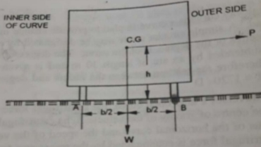
P.h = W x 
For no over-turning condition,
[ =
=  ] ≤
] ≤ 
2. Transverse Skidding Effect (tendency to skid the vehicle laterally outwards)
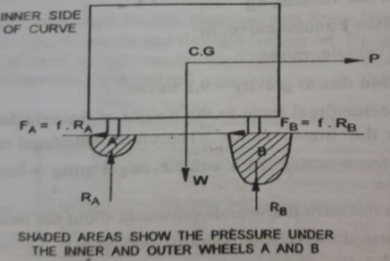
Frictional force = Fw
Centrifugal force = P = 
For no skidding condition, centrifugal force ≤ frictional force
[ =
=  ] ≤ f
] ≤ f
Super Elevation
Super Elevation is the transverse slope to counteract the centrifugal force and to reduce the tendency of the vehicle to overturn or skid.
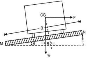
e =  = tan
= tan
Since is extremely small,
Tan ≈ sin = 
Where, B = pavement width
And E = relative elevation of outer edge
Calculation of Super Elevation
The following forces act on vehicle while moving on a circular curve of radius R with speed V m/sec:
a) Centrifugal force P acts horizontally outwards through C.G
b) Weight of the vehicle W acts vertically downwards through C.G
c) Frictional force acts inwards towards the center of the curve
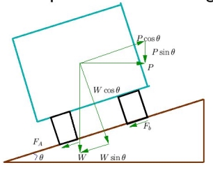
For equilibrium,
P cos = W sin + f (W cos + P sin )
P (cos - f sin ) = W sin + f.W cos
 =
=  = e + f
Also,
e + f =  =
=  (v is speed of vehicle in m/sec)
We can also say, e + f =  =
=  (V is speed of vehicle in kmph)
R = radius of curve in metre
e = rate of super elevation = tan
f = design value of lateral friction = 0.15
Minimum & Maximum Value of Super Elevation (IRC Recommendations)
Maximum Value of Super Elevation
emax = 7% for plain & rolling terrain
emax = 10% for hilly terrain without snow
emax = 4% for urban roads with frequent inter-sections
Minimum Value of Super Elevation
emin = camber from drainage consideration
Attainment of Super Elevation
Complete super elevation is attained at the end of transition curve or at the beginning of the circular curve. The attainment of super elevation can be split into two parts:
a) Elimination of the crown of the cambered section
b) Rotation of the pavement to attain full super-elevation
There are two methods of rotation of pavement after eliminating camber:
- Rotation about centre line

Depressing inner edge by E/2 and outer edge by E/2.
The advantage of this method is that the earthwork is balanced.
The disadvantage of this method is the drainage problem due to depression of the inner edge.
2. Rotation about inner edge
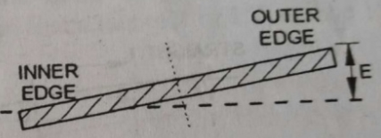
Outer edge of the pavement is raised by E.
The advantage of this method is that it can be used in areas of high rainfall and level terrain to avoid drainage problem.
Ruling Minimum Radius of Horizontal Curve
Minimum radius of horizontal curve is given by the following equation:
Rmin = 
Where, V = minimum or ruling design speed in kmph
e = Rate of super-elevation
f = Design value of lateral friction
Ruling Minimum Radius
a) For NH & SH = 360m
b) For MDR = 230m
c) For ODR = 155m
d) For VR = 90m
Summit curves are vertical curves which are formed when two gradients meet such that there is no discomfort to passengers. But, the main problem in summit curves is to provide adequate sight distance.
Ideally, circular summit curves are best as the sight distance available throughout the summit curve is constant. However, practically simple parabolic curves are used because of best riding qualities, simplicity of calculation work and uniform rate of change of grade. The equation for parabolic summit curves is as follows:
y =a.x2
Where, a = N/2L
N is the deviation angle and L is the length of the curve.
Minimum radius of parabolic curve summit curve is given by R = L/N
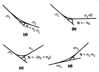
Calculation of Deviation Angle
Length of Summit Curves (L) for Stopping Sight Distance (SSD)
Case 1: L > SSD
L = 
Where, L = Length of Summit Curve (m)
S = SSD (m)
N = deviation angle = algebraic sum of grade
H = height of eye level of driver above road surface = 1.2m
h = height of object above pavement surface = 0.15m
Now, if H = 1.2m and h = 0.15m, then L = 
Case 2: L < SSD
L =  = 2S –
Length of Summit Curves (L) for Overtaking Sight Distance (OSD) and Intermediate Sight Distance (ISD)
Case 1: L > OSD or ISD
L = 
Where, L = Length of Summit Curve (m)
S = OSD/ ISD(m)
N = deviation angle = algebraic sum of grade
H = height of eye level of driver above road surface = 1.2m
Now, if H = 1.2m, then L = 
Case 2: L < OSD or ISD
L =  = 2S –
A road intersection is defined as a junction where two or more roads or streets meet or cross each other. Intersections may be classified into two broad groups:
a) Intersection at grade
- These include all roads which meet at more or less the same level.
- Traffic maneuvers including merging, diverging and crossing are involved in intersection at grade.
- Basic Requirements for Intersection at grade:
- At the intersection, the area of conflict should be as small as possible.
- The relative speed and angle of approach of vehicle should be small.
- Adequate visibility should be available to vehicles that approach the intersection.
- Sudden change of path should be avoided.
- Types of Intersections at Grade
- Un-channelized Intersections
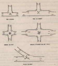
The intersection area is paved and there is no restriction to vehicles to use any area of the intersection.
Plain intersection: no additional pavement width for turning movement is provided
Flared intersection: pavement area is widened at the intersection area by one or more traffic lanes
B. Channelized Intersections
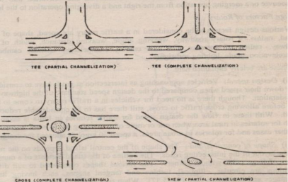
The intersection area consists of small islands in the intersection area, thereby reducing the total area of conflict at the intersection.
C. Rotary Intersections
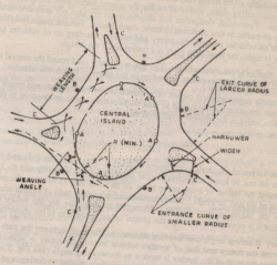
These are special form of at-grade intersections laid out for the movement of traffic in one direction around a central traffic island.
The vehicles entering the rotary are gently forced to move in a clockwise direction in an orderly manner.
Advantages:
a) Traffic flow is regulated to only one direction of movement, thus eliminating severe conflicts between crossing movements.
b) All vehicles entering a rotary are gently forced to reduce the speed and continue to move at slower speed. Thus, none of the vehicles need to be stopped.
c) Accidents and their severities are much less in rotaries.
d) Self-governing and do not need any control by police or traffic signals.
e) Ideally suited for moderate traffic.
Disadvantages:
a) All vehicles are forced to slow down and negotiate the intersection. Therefore, the cumulative delay is higher.
b) Vehicles are forced to reduce their speed even in low-traffic conditions.
c) Rotaries require large area of flat land making them costly at urban areas.
d) Cannot support large pedestrian traffic.
Guidelines for Selection of Rotary
a) Suitable when traffic entering from all four approaches is relatively equal.
b) A total volume of about 3000 vehicles per hour can be considered as the upper limiting case and a volume of 500 vehicles per hour is the lower limit.
c) Suitable when there are four or more than four approaches.
d) Very beneficial when proportion of right turning traffic is 30% of the total traffic.
Design Elements
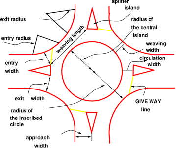
- Design Speed: 40 kmph for rural areas and 30 kmph for urban areas.
- Entry Radius: 20-35m for rural areas and 15-25m for urban areas.
- Exit Radius: 1.5-2 times of entry radius.
- Island Radius: 1.3 times of entry radius.
- Width of weaving section = Wweaving=
 ) + 3.5
Where, e1 = width of carriageway at entry
And e2 = width of carriageway at exit
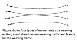
- Weaving length is the minimum length of the rotary roadway that allows smooth merging and diverging of vehicles between the two channelizing islands of adjacent intersecting legs.
Weaving length= 4 x weaving width
Weaving length is 45-90 m for rural and 30-60 m for urban areas.
- Shape of Rotary depends upon the number and layout of the intersecting roads. The various shapes that may be used are circular, elliptical, turbine and tangential.
- Capacity of Rotary: Qw =
 where,
w = width of weaving section (within a range of 6-18m)
e = average entry width (in metres) (e/w ratio must be between 0.4-1)
l = weaving length (w/l ratio must be between 0.12-4)
p = proportion of weaving traffic to non-weaving traffic (must be between 0.4-1) = 
Q. The width of approaches for a rotary intersection in an urban area is 12m. The entry and exit width at the rotary is 10m. Table below gives the traffic from four approaches traversing the intersection. Find the capacity of the rotary.
Approach | Left Turn | Straight | Right Turn |
North | 300 | 500 | 400 |
South | 300 | 350 | 420 |
East | 250 | 400 | 500 |
West | 300 | 400 | 350 |
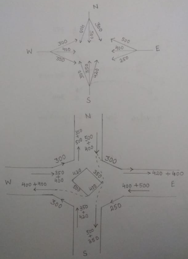
Movement of Traffic along Rotary
Width of weaving section = Wweaving=  ) + 3.5 =
  ) + 3.5 = 13.5 m
Weaving length = l = 4 x Wweaving = 4 x 13.5 = 54 m
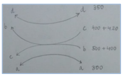
Calculation of p-value for North-East Direction
pNE =  = 0.73
pES =  = 0.7
= 0.7
pSW =  = 0.66
pNW =  = 0.69
The highest value out of these which is 0.73 will be used for design of rotary capacity.
Qw = 
Qw =  = 3980 vehicles/hour
b) Grade separated intersection
- These are further classified as over-pass and under-pass.
- Over-pass: when we raise the profile of the major highway above the general ground level by means of an over-bridge across another highway
- Under-pass: when we depress the profile of the major highway below the general ground level to cross another road by means of an under-bridge
- Choice of over-pass or under-pass depends upon topography, vertical alignment, drainage, economy, aesthetic features etc.
Reference Books:
- S.K. Khanna and C.E.G. Justo - Highway Engineering - 10th Edition, Nem Chand and Bros. Roorkee
- L.R. Kadiyali - Traffic Engineering and Transport Planning - Khanna Publishers