Unit -3
Construction method
There may be variations as every project is unique and follows different design and construction process. In general, the basic steps involved in a building project are briefly explained.
3.1.1 Planning
The planning in building construction involves three major steps:
Once the site where the building project is indented to construct is chosen, the expertise of engineers and architects are taken to develop the site and the building plan. Sometimes, an appropriate site is selected after the building layout is prepared. The building plan is developed based on the owner’s requirements and budget.Once the plan is in hand, the finance and total cost is estimated. The structural design details, the material estimates are prepared which help to derive project cost estimate. The cost calculated include:
Based on the estimated cost, either a bidding process is performed or the project to handover to a known contractor. The contractor and the owner must agree to contract based on which the project is implemented. The contract mentions the completion period and necessary guides, exclusions to remove claims.
3.2.2. Permits and Insurance in Building Construction
Before starting a building construction, the owner must make sure that one has necessary permits taken to start the construction. Permits and insurance are obtained from different sources in cities and states.
A construction work conducted without permits results in project delay or project demolition or huge fines. Possessing insurance for the required parties helps to save the owner and the contractor.
3.1.3. Site Preparation
From here, the actual construction process starts. Based on the site and building plan, necessary excavations, leveling, and filling can be undergone to prepare the site. The necessary excavation for utilities, power, water and sanitation lines, and temporary storage facilities are prepared. Mostly the works needed to set up the utilities are prepared. This is followed by an inspection from the government officials.
Inspections are performed at different stages on structural, building codes, the utilities, HVAC, electrical works etc. After the completion of the whole project, a final inspection is performed.
3.1.4. Foundation / Substructure Construction
Building structures are generally constructed on concrete foundations. Based on the soil type and water table level of the area, the foundation chosen can vary. If necessary, soil testing is performed to check the bearing capacity. Shallow foundations are required for low-rise building. For high-rise building, pile foundation is employed.
Once the foundation is selected, the soil is excavated to construct the foundation. It is performed based on the foundation layout. Formworks are placed in the foundation trenches and reinforcement is placed based on the foundation detailing design prepared in the planning stage. The reinforcement works performed by the contractor is periodically checked by the engineer in charge.The concrete mix of the required proportion is poured to formwork and is cured to form the finished foundation.
3.1.5. Superstructure Construction
The superstructures constructed once the substructure is complete. Generally, a framed structured is developed which is later finished with masonry walls. Adequate windows and exterior doors are placed based on the building plan. Other works coming under this section is:
3.1.6. Punch List
Once the project is complete, the contractor inspects the whole work one by one and make a punch list. Those structural units or areas that were not constructed properly or are below the quality level is listed in the punch list. This is later corrected by the contractor in charge.
3.1.7. Warranty Period
Once the project is complete and handovered to the owner, the contractor specifies a warranty period. Within this period, any defects found in building constructed must be fixed and replaced by the contractor in charge. The warranty for materials and appliances are obtained from manufacturers and suppliers.
3.2.1 Shallow Foundations:
Foundations provided immediately beneath the lowest part of the structure, near to the ground level are known as shallow foundations. Such foundations are mostly placed on the first hard and firm strata available below the ground level. Shallow foundations are further classified into the following types:
3.2.1.1 Spread Footing Foundations
Foundations constructed by increasing the are at the base of the structure by means of offsets, are called spread footing foundations. In such foundations, spread is given under the base of a wall or a column by providing offsets. This spread is known as footing and the foundation itself is called spread footing.
Broadly speaking, all types of shallow foundations can be referred to as spread footing foundations. However, from design and construction point of view, they have been designated separately. The various types of spread footing foundations are;
a) Wall footings:
This is a common and the simplest type of spread footing foundation; It consists of a number of courses of bricks, the lowest being usually twice the thickness of wall above. In this type of foundation, the base width of the wall is increased by providing 5cm (one-fourth of brick length) offsets on either side of the wall. The depth of each course is usually 10 cm
In some cases, however, the bottom course is made 20cm deep. In the case of footing for store walls, the size of offset is slightly more than that of the brick wall footing.
Method of Construction of Wall Footing:
For constructing wall footing, a bed of lean cement concrete (1:8:16) is first laid over the entire length of the wall. The thickness of this lean concrete bed is usually kept 15cm and its width is kept 20 to 30 cm more than that of the bottom course.
In no case, the depth of the concrete bed should be less than its projection beyond the wall base. For foundations over firm soil or compacted ground, the concrete bed below the brick wall footing may be dispensed with. After laying the concrete for constructing the concrete bed, it should be properly compacted and cured before laying the base course of the wall.
Suitability:
This is the cheapest type of spread footing foundations and is largely used for walls of ordinary buildings.
b) Masonry Pillar Footing
Isolated footings are used to support the individual pillars and columns constructed in brick or stone masonry. They are stepped down in the wall footing after providing 15cm offset of foundation concrete on all the sides.
c) Concrete Column Footing:
These are either stepped type, slate type or slope type, having projections in the vae concrete. To support heavy loads, reinforcement is also provided at the base. The reinforcement provided is in the form of steel bars and is placed in both directions. Concrete column footings may be either isolated footings or combined footings. Isolated footings are used to support the individual columns, whereas combined footings are used where projections of different columns are not possible on all the sides, due to limited space.
The combined footings are generally rectangular in shape when both columns are of same sections and trapezoidal in shape when the columns are of different sections.

3.2.1.2 Grillage Foundation
The foundation which consists of one or two tiers of wooden or rolled steel section with space filled up with concrete is known as Grillage foundation. This is so called because the bed constructed in this type of foundation is called grillage. This type of construction avoids deep excavation and provides the necessary area at the base of the structure to reduce the intensity of pressure within the safe bearing capacity of the soil.
OBJECT
:The object of this type of foundation is to spread the load over a large horizontal area at the base of a structure.
Types of Grillage Foundation
Depending upon the material used in construction, grillage foundations are further classified into two types.
Steel Grillage Foundation
Method of construction of steel grillage foundation
For timber grillage foundation construction
Steel grillage foundations are useful for structures like columns, piers, stanchions subjected to heavy concentrated loads and hence are employed for foundations of the buildings such as theaters, factories, town, halls etc. Timber grillage foundations re usually provided for timber columns subjected to heavy concentrated loads. This type of grillage foundation can also be safely used for light buildings where the soil encountered is soft and is permanently water-logged.
3.2.1.3 Raft foundation
The foundation consisting of a thick R.C.C slab covering the whole area of a mat is known as raft foundation.
Method of construction of Raft Foundation
This type of foundation is useful for public buildings, office buildings, school buildings, residential quarters etc, where the ground conditions are very poor and bearing power of the soil is so low that individual spread footing cannot be provided.
3.2.1.4 Stepped foundation
Another types of foundation is stepped foundation, For Stepped Foundation Construction, excavation is done into steps having short length and uniform thickness and the masonry work is done on the horizontal bed of concrete thus prepared.
If there is any possibility of slipping of the structure bodily, R.C.C piles can be driven along its base concrete on the sloping side.
3.2.1.5 Inverted arch foundation
The foundation consisting of inverted arches between the piers is known as inverted arch foundation. In this type of foundation, the load from the piers is transferred to the soil by constructing arches in inverted position at their at their base. The rise of the inverted arches is about one - fifth to one - tenth of the span and they are usually build in half-brick rings. The position of arches may be either along the row of piers or across the row of piers in both the directions depending upon the nature of soil and the type of land to be taken by them.
This of foundation is not commonly used for buildings, but it is quite suitable for other structures like bridges, reservoirs, tanks, supports for drainage lines etc.
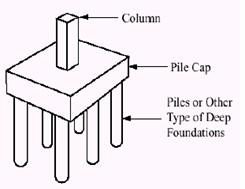
3.2.2 Deep foundation
The foundation constructed sufficiently below ground level with some artificial arrangements such as piles, wells etc, at their base are called deep foundations. Deep foundation are further classified into the following types ;
1. pile foundation
A foundation (spread footing or grillage) supported on piles is called a pile foundation. A pile foundation usually consists of a base of spread footing or grillage supported by piles at their bottom. Piles distribute the load of structure to the soil in contact either by friction alone or by friction combined with bearing at their ends.
3.2.3 Method of construction
For constructing this type this type of foundation;
Design and building concrete formwork effectively requires a basic understanding of how concrete behaves as it exerts pressure on formwork. Concrete exerts lateral pressure on the formwork. The formwork is designed based on these lateral forces.
Concrete Formwork Design Considerations
Lateral concrete pressure on formwork is affected by:
Height of concrete pour: Before concrete hardens, it acts like a liquid and pushes against the forms the way water presses against the walls of a storage tank. The amount of pressure at any point on the form is directly determined by the height and weight of concrete above it. Pressure is not affected by the thickness of the wall.
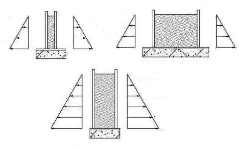
Concrete pour rate: Concrete pressure at any point on the form is directly proportional to the height of liquid concrete above it. If concrete begins to harden before the pour is complete, the full liquid head will not develop and the pressure against the forms will be less than if the pour were completed before any of concrete hardened.
Once concrete hardens it cannot exert more pressure on the forms even though liquid concrete continues to be placed above it. The following diagrams illustrates how form pressure varies when the pour rate is increased from one level to another level. For ease of explanation, it is assumed that concrete hardens in one hour (typically) at 21°C.


Fig: Concrete pressure on formwork during hardening
When the pour rate is increased the pressure also increases as shown below:
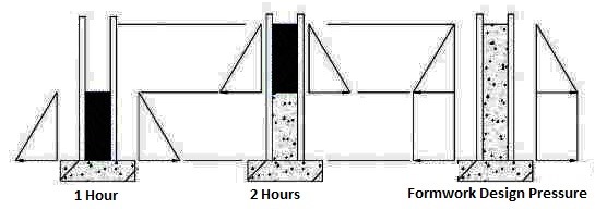
Fig: Concrete pressure on formwork due to higher pour rate
Weight of Concrete: Pressure exerted against the forms is directly proportional to the unit weight of concrete. Lightweight concrete will exert less pressure than normal weight concrete as shown below:
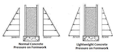
Fig: Pressure on formwork due to normal and lightweight concretes
Temperature: The time it takes concrete to harden is influenced greatly by its temperature. The higher the temperature of the concrete, the quicker it will harden. Most formwork designs are based on an assumed average air and concrete temperature of 21°C.
At low air temperatures, the hardening of concrete is delayed and you need to decrease your pour rate or heat your concrete to keep the pressure against the formwork from increasing.
Ideally, concrete should be poured at temperatures between 16°C and 38°C. Outside this temperature range there is often insufficient moisture available for curing. If adequate water for curing is not available or freezes, the strength of the concrete will suffer.
Type of Cement: The cement type will influence the rate at which concrete hardens. A high early strength concrete will harden faster than normal concrete and will allow a faster pour rate. When using a cement which alters the normal set and hardening time, be sure to adjust the pour rate accordingly.
Vibration: Internal vibration consolidates concrete and causes it to behave like the pure liquid. If concrete is not vibrated, it will exert less pressure on the forms. ACI recommended formulas for form pressures may be reduced 10% if the concrete is spaded rather than internally vibrated. Re-vibration and external vibration result in higher form loads than internal vibration. These types of vibration require specially designed forms.
7) Concrete Slump: When concrete has very low slump, it acts less like a liquid and will transmit less pressure. When using concrete with a slump greater than 100 mm, the formwork should be designed to resist full liquid head.
8) Chemical additives: When using chemical additives – i.e. retarders, plasticizers, etc. – make sure to refer to the vendor’s application data.
3.4.1. Traditional stick framing:
This process involves a building system in which workers will assemble the main skeleton of your home. The construction system actually begins when skeleton items including wall studs, ceiling joists, roof trusses, rafters and then all flooring systems are installed. These items will be installed step-by-step and then eventually build a platform for the entire home.
s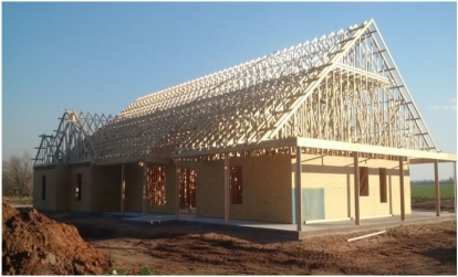
Traditional stick framing processes start with the base floor and then adds the second story eventually adding in the roof framing. A number of smaller homes have prebuilt wall panels and wood frame structures in the home that can have items like electrical work/plumbing and more placed into the framing as it gets built up. Following the process of inspection inside the walls, they are usually then covered with drywall and the exterior of the home is then coated with stucco, bricks, or siding to protect it from the elements.
Traditional stick framing is a tested and well-used method. It has been used throughout North America over the decades. New-home construction with traditional stick framing is a time tested method now.
3.4.2.Modular homes:
Modular homes continue to use the same type of method for conventional stick framing but they are built-in off-site conditions. This can often lead to a home that can be built much more efficiently and then hold its value well. Modules are built entirely in a factory and then assembled on the job site. They get moved into a place with a crane and they are constructed in some of the same measures that a traditional stick framing method is used. The only opposing change with traditional stick framing homes and modular homes is that these homes are assembled in small modules and then trucked to the site.
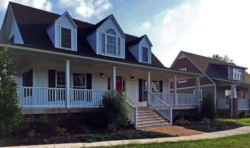
Builders will take modular homes and knit the various modules together to create a custom-built home that follows extremely complex designs. Popular architectural features can be added into modules to produce almost any type of home.
3.4.3.Light gauge steel:
Light gauge steel is a process that involves building in a similar way as traditional stick framing but with a light difference. Instead of the wooden design of the stick-built home, each of the components is instead made out of metal. The big advantage here is that any of this deal will not rot, shrink or experience damage from termites. Steel can last longer than any type of wood frame and there is less worry for things like drywall cracks, warping or shrinking.
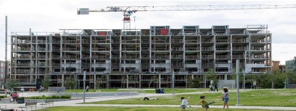
Light gauge steel designs are often a bit more expensive for a build but they can often be beneficial for adding rigidity to the home as well as a longer lifespan for any type of property. Light gauge steel is a common tool for many types of commercial buildings and it’s starting to make its way into many residential buildings as well.
Steel studs do pose a number of challenges for plumbers and electricians. The overall cost of steel also fluctuates far more than other building materials in the market which can lead to costs going up substantially.
3.4.4.Structural insulated panels:
A structural insulated panel is otherwise called SIP. This solution is a small sandwich of rigid foam installations that are placed between an oriented strand board. This can create the structural panel that makes up the main element of a home.
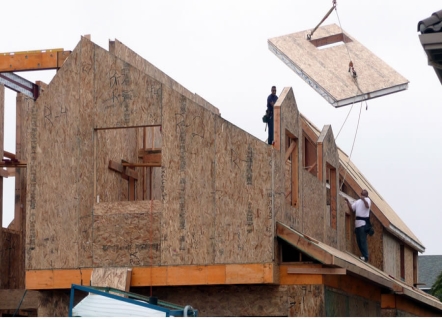
SIPs often come with door openings and precut windows and they are usually constructed with areas for electrical wiring. These building methods are common for use in producing ceilings and walls. Specifically trained crews are required to assemble them on the job site.
These types of building processes are the most common for producing traditional timber frame, post-and-beam structures as well as self-supporting homes. SIP homes are often designed with improved insulation and they are built to be draft-free. This can also ensure that she save money on the cost of their electricity bills and the labor on the home as well. Because the materials take far less time and labor to assemble and the insulation is already in place, this is an option that is less expensive for the future of the building.
3.4.5 Concrete:
Concrete has also become one of the most popular materials which are available for the foundations of homes and for a series of single-family homes for walls too. Wood framing is commonly used as part of concrete installations and for accenting the concrete installations themselves. The wood framing can be used with concrete forms to produce ceilings, internal walls, and roofs.
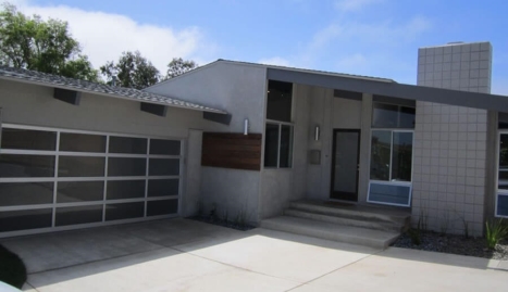
There are several different types of concrete installations that are present during concrete construction:
CMUs:
Concrete masonry units are made using hollow concrete blocks which are stacked on-site and then covered with a foam insulation board. The blocks provide a thermal mass which can slow down the transfer of heat. The inside of a home often stays cooler on a hot day and this is what makes these products so popular throughout the southern states. CMU homes are surprisingly affordable and they can actually be priced quite competitively with wood framing.
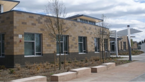
AAC blocks:
Autoclave Aerated Concrete blocks are a variation of concrete masonry units. They are made using a specialty concentration of Portland cement, fly ash, aluminum, and other additives. The base chemical reactions between some of these materials as well as the microscopic air bubbles inside will act as insulation. Their costs are also traditionally more than many standard CMUs but they have improvements with strength and insulation over time.
ICFs:
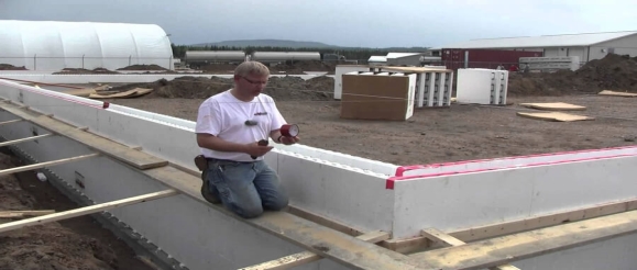
Insulated concrete forms are designed to be blocks that work like lego. There assembled directly on-site and are often filled with steel reinforcing rods as well as concrete for improvements in insulation. Their value is much higher than most of the wood-framed walls and they’re perfect for almost any climate. ICFs are only slightly more expensive than wood-framed homes and they deliver a similar design. The actual price of these materials can depend on the local market but these have become a very popular type of material for areas that face high winds and hurricanes.
No matter what type of modern building construction method that you would want to use for your industrial, commercial or residential building, it can be helpful to have an idea of how it will be constructed. Deciding between some of these materials could help you to prepare the best option for your property.
In order to understand the construction of precast concrete structure, different precast systems shall be known.
There are four major types of precast systems which are classified based on the on the load bearing structure:
3.5.1 Large Panel System
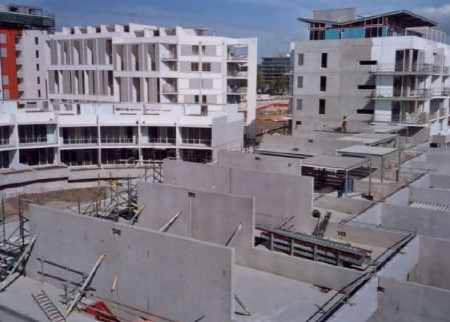
Large panel systems are useful for the construction of apartments and hotels. It consists of large walls and floor concrete panels connected in the vertical and horizontal directions.
Both horizontal and vertical panels withstand gravity loads. There are three arrangements of large panel system based on wall layouts which include cross-wall system, longitudinal-wall system, two-way system.
3.5.2 Frame System
It is suitable for the construction of car parks, stadia, and offices. Precast frames can be constructed using either linear elements or spatial beam-column sub assemblages.
Precast beam-column sub-assemblages have the advantages that the connecting faces between the sub-assemblages can be placed away from the critical frame regions.
However linear elements are generally preferred because of the difficulties associated with forming, handling and erecting spatial elements.
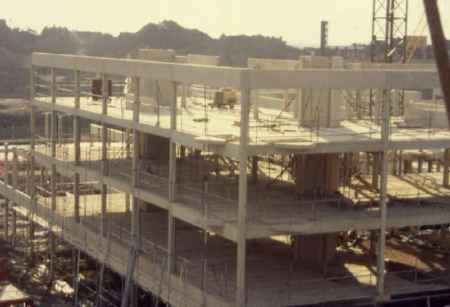
3.5.3 Slab-Column System with Shear Wall
In this system, gravity loads supported by slab-column structure whereas shear walls withstand lateral loads. There are two types of slab-column system with shear walls namely; lift slab system with walls and pre-stressed slab-column system.
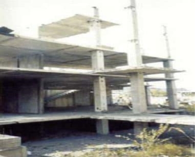
Slip forming, continuous pouring, continuous forming or slip forming is a construction technique during which concrete is poured into a continuously moving form.
Slip making is used for tall constructions as well as horizontal constructions such as roadways.
Slip forming allows continuous, non-interruption, cast-in-place flawless concrete structures with superior efficiency characteristics to piecewise construction using discrete form components.
Sheathing or vertical forms are the components of slip form Vertical forms can be wood staves, metal, plywood, glass-fibre reinforced plastic or a combination of this materials.
The function of vertical forms is to shape the concrete.
Wales:
It is also an important component of vertical slip forms supports and holds vertical forms in place.
This transmits the lifting force from the yoke to the vertical forms and other elements of the form.
It also supports various platforms and scaffolds.
Yokes:
It is the component of vertical slip formwork supports the wales at regular interval with their legs.
It transmits the lifting forces from the jacks to the wales and resists the lateral force of plastic concrete within the form.
Jacks:
It is installed on the yoke’s beam.
It mounts on the jack rod and provides the necessary force to lift the entire slip form system
Various platforms, decks and scaffolds complete the slip form system, provides space for storage of concrete, reinforcing steel and embedding.
In short, they serve as a work area for placing and finishing
Jack rods:
These are climbed up by Jacks.
3.6.1 Types of slip formwork
3.6.1.1 Vertical slip formwork
The vertical slip form depends on the quick setting properties of the concrete that is required between the initial strength gain and the ability to work.
Placing the concrete into the formwork requires sufficient work to be done practically, it is sufficiently strong to develop the initial strength so that the form slips freshly onto the concrete without any disturbance.
While the concreting process, hydraulic lifters extend the formwork for the entire horizontal projection of a given structure in a continuous sliding motion upward.
Work platforms are permanently attached to the top of the vertical slip form & they are suspended from inside and outside slip form are light in weight.
3.6.1.2.Cantilever jump from method
In vertical slip form there is no need to erect and destroy expensive scaffolding.
In the cantilever jump form slip formwork method, the lifting device is synchronized by electric motors.
This system is that climbers are independent of cranes and attached to a large area of formwork at storey height.
In this system, shuttering has already been completed, which is part of the structure between individual levels of climbers.
The cantilever jump form system gives maximum protection, providing a complete self-climbing formwork system that is independent of cranes for walls, columns, supports and floor beers.
3.6.1.3 Egg shape slip formwork
Egg-shape slip formwork is based on the jump form principle that can be adapted to any geometric shape.
If this system, when the egg-shaped circumference changes, the cantilever plate on the periphery is removed or extended.
Individual curvature adjustment can be obtained by adjusting the axis and vertical circumferential slope.
The system can be adjusted independently on each side of the wall as well as products of optimal working condition.
It also shows clear savings in time and personnel costs.
3.6.1.4 Conical formwork system
Conical formwork is a system by which it is possible to construct structures of varying wall thicknesses and tapering walls.
It is also possible to construct structures whose formwork changes geometrically from angular to circular.
The conical formwork is made up of cantilever plates and overlapping plates, which are fastened to steel yoke frames.
The cantilever plate and overlapping plates automatically adjust the formwork geometry.
It features integrated scaffolding systems consisting of horizontal work platforms that provide an optimal and safe working area for labour, engineers and supervisors.
USES OF SLIP FORMWORK:
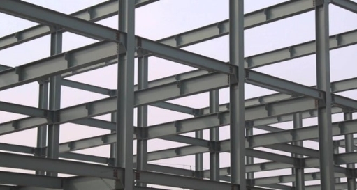
Construction of Steel Frame Structure Foundation
Steel framed structure construction begins with the construction of its foundation. Generally, the types of foundation required for the given structure is based on the soil bearing capacity.
Soil investigation including surface and subsurface exploration is used to assess the condition of soil on which steel frame structure rests.
For example, when moderate or low loads are imposed, then it is advised to use reinforced concrete bearing pads or strip foundation. These foundation types transfer loads to soil capable of supporting transferred loads.
Pile foundation to transfer loads of steel frame structure though low soil bearing capacity of stiff soil with adequate bearing capacity
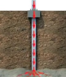
Fig: Steel Bearing Pile Driven into Ground
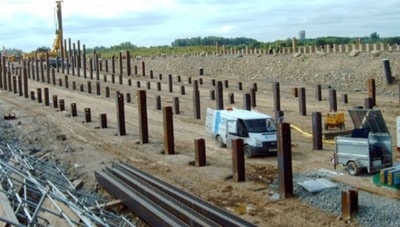
Steel Bearing Pile Driven into Ground
3.7.1 Steel Column Construction
The next step of steel frame construction is the placement of steel columns. The section of the steel is specified based on the load imposed.
There are various sizes of steel column section to choose and these steel columns are commonly produced in advance.
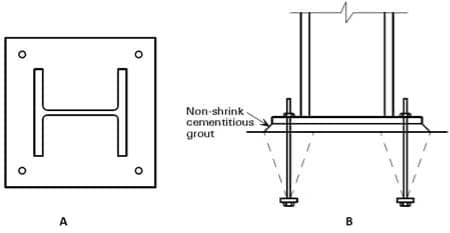
The most significant point in column installation is the connection between foundation and column and splices between columns.
Regarding foundation to column joints, base plates are welded to the end of columns. The most desired shape of base plate is square and rectangular shape.
It should be known that, the most desired shape of base plate is rectangular and square shape because such plates provide largest spacing between the bolts which is desirable.
Described below are the different methods employed in the construction of bridges.
3.8.1. Cast-in-situ Method of Bridge Construction
This method is a flexible method of bridge construction where complex and unusual geometrical shapes of dams can be constructed easily. Situations when it is hard to transport pre-fabricated elements either due to size or unreachability, this method is a good choice.
3.8.2. Balanced Cantilever Method of Bridge Construction
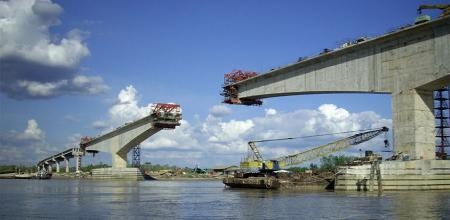
This method is used for constructing bridges with span 50 to 250m. The bridge constructed can either be cast-in-place or precast. Here, the segments are attached in an alternative manner at opposite ends of the cantilevers supported by piers. This is the best choice for the construction of long span length bridges, irregular length, and cable-stayed bridges.
3.8.3. Precast Method of Bridge Construction
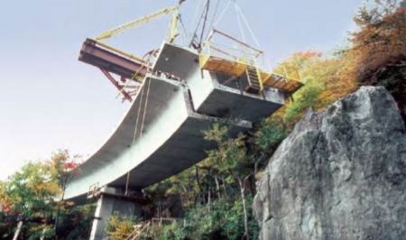
In this method, the bridge is constructed with the help of precast concrete elements. The prefabrication is performed in different methods. The precast elements include:
3.8.4. Span by Span Casting method of Bridge Construction
This method is associated with cantilever construction method but with many advancements in the technique, it is considered as most economic and rapid in construction. For long bridges and viaducts with an individual span up to 60m, the method is feasible.
Decks are begun at one abutment and constructed continuously by placing segments to the other end of the bridge. Segments can be positioned by either a temporary staying mast system through more commonly using an assembly truss.
3.8.5. Incremental Launching Method of Bridge Construction
The Incremental Launching Method (ILM) method of bridge construction is employed mainly for the construction of continuous concrete bridges or steel girder bridges. The method performs the procedure in increments. With this method of construction, the bridge deck is built in sections by pushing the structure outwards from an abutment towards the pier. The ILM method can be used for bridge decks with a length greater than 250m.
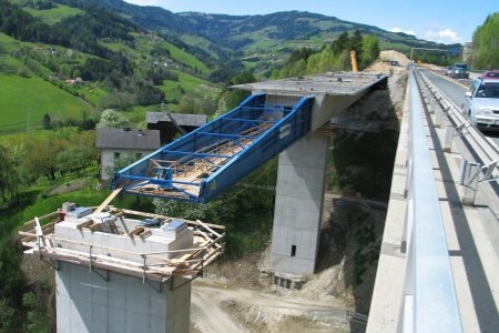
3.8.6. Cable-Stayed Method of Bridge Construction
In the cable-stayed method of construction, cables are used to carry the bridge deck from one or both sides of the supporting tower. The cables carry and transfer all the loads to the foundations. Cable-stayed method of construction is used for constructing bridges that span more than 300m.
3.8.7. Arch Method for Bridge Construction
Arch shaped bridge construction is one of the most economical choices when the bridge under consideration is required to cross over landscapes that are inaccessible. Many modern arch construction methods have made the arch construction more economical. The arch construction can be built with concrete or pre-cast concrete. The cast-in-situ free cantilever method and slip formed sections are two main construction techniques coming under arch methods.
Key-takeaways- The contractor and the owner must agree to contract based on which the project is implemented. The contract mentions the completion period and necessary guides, exclusions to remove claims.
Reference
1. Punmia ,B.C khandewala k.k. project planning with PERT and CPM,laxmi publication,2016.
2. National building code ,bureau of Indian standards ,new delhi,2017.